EP1142480A2 - Cooling method and system for a rotating drum - Google Patents
Cooling method and system for a rotating drum Download PDFInfo
- Publication number
- EP1142480A2 EP1142480A2 EP01400786A EP01400786A EP1142480A2 EP 1142480 A2 EP1142480 A2 EP 1142480A2 EP 01400786 A EP01400786 A EP 01400786A EP 01400786 A EP01400786 A EP 01400786A EP 1142480 A2 EP1142480 A2 EP 1142480A2
- Authority
- EP
- European Patent Office
- Prior art keywords
- heat transfer
- product
- transfer fluid
- nozzles
- drum
- Prior art date
- Legal status (The legal status is an assumption and is not a legal conclusion. Google has not performed a legal analysis and makes no representation as to the accuracy of the status listed.)
- Granted
Links
Images

Classifications
-
- A—HUMAN NECESSITIES
- A23—FOODS OR FOODSTUFFS; TREATMENT THEREOF, NOT COVERED BY OTHER CLASSES
- A23B—PRESERVING, e.g. BY CANNING, MEAT, FISH, EGGS, FRUIT, VEGETABLES, EDIBLE SEEDS; CHEMICAL RIPENING OF FRUIT OR VEGETABLES; THE PRESERVED, RIPENED, OR CANNED PRODUCTS
- A23B4/00—General methods for preserving meat, sausages, fish or fish products
- A23B4/06—Freezing; Subsequent thawing; Cooling
- A23B4/08—Freezing; Subsequent thawing; Cooling with addition of chemicals or treatment with chemicals before or during cooling, e.g. in the form of an ice coating or frozen block
- A23B4/09—Freezing; Subsequent thawing; Cooling with addition of chemicals or treatment with chemicals before or during cooling, e.g. in the form of an ice coating or frozen block with direct contact between the food and the chemical, e.g. liquid N2, at cryogenic temperature
-
- A—HUMAN NECESSITIES
- A23—FOODS OR FOODSTUFFS; TREATMENT THEREOF, NOT COVERED BY OTHER CLASSES
- A23B—PRESERVING, e.g. BY CANNING, MEAT, FISH, EGGS, FRUIT, VEGETABLES, EDIBLE SEEDS; CHEMICAL RIPENING OF FRUIT OR VEGETABLES; THE PRESERVED, RIPENED, OR CANNED PRODUCTS
- A23B4/00—General methods for preserving meat, sausages, fish or fish products
- A23B4/26—Apparatus for preserving using liquids ; Methods therefor
-
- A—HUMAN NECESSITIES
- A23—FOODS OR FOODSTUFFS; TREATMENT THEREOF, NOT COVERED BY OTHER CLASSES
- A23B—PRESERVING, e.g. BY CANNING, MEAT, FISH, EGGS, FRUIT, VEGETABLES, EDIBLE SEEDS; CHEMICAL RIPENING OF FRUIT OR VEGETABLES; THE PRESERVED, RIPENED, OR CANNED PRODUCTS
- A23B4/00—General methods for preserving meat, sausages, fish or fish products
- A23B4/32—Apparatus for preserving using solids
-
- B—PERFORMING OPERATIONS; TRANSPORTING
- B01—PHYSICAL OR CHEMICAL PROCESSES OR APPARATUS IN GENERAL
- B01F—MIXING, e.g. DISSOLVING, EMULSIFYING OR DISPERSING
- B01F35/00—Accessories for mixers; Auxiliary operations or auxiliary devices; Parts or details of general application
- B01F35/90—Heating or cooling systems
-
- F—MECHANICAL ENGINEERING; LIGHTING; HEATING; WEAPONS; BLASTING
- F25—REFRIGERATION OR COOLING; COMBINED HEATING AND REFRIGERATION SYSTEMS; HEAT PUMP SYSTEMS; MANUFACTURE OR STORAGE OF ICE; LIQUEFACTION SOLIDIFICATION OF GASES
- F25D—REFRIGERATORS; COLD ROOMS; ICE-BOXES; COOLING OR FREEZING APPARATUS NOT OTHERWISE PROVIDED FOR
- F25D3/00—Devices using other cold materials; Devices using cold-storage bodies
- F25D3/10—Devices using other cold materials; Devices using cold-storage bodies using liquefied gases, e.g. liquid air
-
- F—MECHANICAL ENGINEERING; LIGHTING; HEATING; WEAPONS; BLASTING
- F25—REFRIGERATION OR COOLING; COMBINED HEATING AND REFRIGERATION SYSTEMS; HEAT PUMP SYSTEMS; MANUFACTURE OR STORAGE OF ICE; LIQUEFACTION SOLIDIFICATION OF GASES
- F25D—REFRIGERATORS; COLD ROOMS; ICE-BOXES; COOLING OR FREEZING APPARATUS NOT OTHERWISE PROVIDED FOR
- F25D29/00—Arrangement or mounting of control or safety devices
- F25D29/001—Arrangement or mounting of control or safety devices for cryogenic fluid systems
Definitions
- the invention relates to a temperature controlling method and system for a rotating drum, and more particularly, the invention relates to a method and system for chilling products in a tumbler type processing drum which includes a plurality of nozzles for controlled delivery of a cooling agent.
- the food processing industry commonly uses rotating drum processing devices which tumble and cool food products such as meat, poultry, and fish. These rotating drums may be used for marinating, massaging, cooling, mixing, or other processes.
- the food products which are generally processed in a rotating drum processor include whole hams, steaks, ribs, chicken parts, whole birds, fish, shrimp, vegetables, and the like.
- the cooling system of a direct injection massager or marinater device involves the delivery of a cooling fluid, such as carbon dioxide or nitrogen, into the drum through a lance with openings formed in it.
- the lance is attached to and supported on a hatch on the rear of the drum.
- the delivery of the cooling fluid in this manner suffers from substantial inefficiencies because a large portion of the cooling fluid goes from the lance to an exhaust without ever coming into contact with the product in the drum.
- These systems also fail to provide uniform cooling of the product.
- the product tends to build up on the lance, partially or fully closing the cooling fluid delivery openings and reducing the ability to deliver cooling fluid.
- the present invention relates to a temperature controlling method and system for a rotating drum type product processing device.
- a temperature control system for a rotating drum including a rotating drum, a plurality of heat transfer fluid delivery nozzles space around and connected to the rotating drum for controlling a temperature of a product in the rotating drum, a plurality of valves associated with the plurality of nozzles, and a control system for controlling the plurality of valves to deliver the heat transfer fluid to a product in the drum when the nozzles are positioned substantially under the product and to prevent delivery of the heat transfer fluid when the nozzles are not substantially under the product.
- a method of controlling a temperature of a product in a rotating drum includes the steps of: placing a product in a rotating drum having a plurality of heat transfer fluid delivery nozzles spaced around and connected to the rotating drum; rotating the drum; and delivering a heat transfer fluid to the product in the drum when the nozzles are positioned substantially under the product and preventing delivery of the heat transfer fluid when the nozzles are not substantially under the product.
- the present invention provides advantages of increased efficiency and uniformity of cooling and reduced clogging of the heat transfer fluid delivery openings.
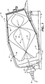
- FIG. 1 illustrates a rotating drum type processing device 10.
- the processing device 10 includes a rotatable drum 14 mounted in a rotatable manner on a support 16 in a manner which is known.
- One or more ends of the drum 14 is provided with a hatch 20 for inserting and removing product from the drum.
- the interior of the drum 14 is provided with one or more helical mixing elements 22 which function to mix and massage the product as the drum is rotated.
- the rotating drum product processing device shown in FIG. 1 is particularly useful for marinating and cooling meat items to gently achieve infusion of marinade into the meat, poultry, seafood, or other food products without damage.
- the drum may also be used for many other processes including tenderizing, cooling, heating, or maintaining a desired temperature.
- the processing device 10 of FIG. 1 also includes a cooling fluid delivery pipe 30 for delivery of a cooling fluid or other fluid to the product.
- the cooling delivery pipe 30 is connected by a rotary coupling 32 to a cooling fluid distribution system for the drum 14.
- the rotary coupling 32 may be a vacuum insulated rotary coupling or the like.
- the cooling fluid distribution system includes a plurality of veins 34 extending longitudinally along the drum 14 and a plurality of nozzles 36 for delivering the cooling fluid from the veins into the interior of the drum.
- the present invention includes a control system which controls delivery of the cooling fluid through the nozzles 36 so that the cooling fluid is injected when the nozzles are positioned under the product in the drum 14 and not when the nozzles are located in open air.
- a control system which controls delivery of the cooling fluid through the nozzles 36 so that the cooling fluid is injected when the nozzles are positioned under the product in the drum 14 and not when the nozzles are located in open air.
- the present invention is expected to provide a 15% to 65% increase in efficiency over conventional systems.
- the efficiency may increase may be 100% or better.
- the increased efficiency is provided by both the cost savings due to reduced cryogen consumption and the time savings due to faster throughput.
- the system for cooling according to the present invention provides a quicker cooling time because more cryogen can be injected faster without fear of losing all the BTUs to the exhaust.
- Increased throughput means that users can meet their processing requirements with fewer massagers or batches.
- FIG. 1 illustrates a plurality of veins 34 and a system of valves 40 for controlling the cooling fluid which is directed from the rotatable coupling 32 to the veins 34.
- the valves 40 are controlled by a control system.
- FIG. 2 is a schematic illustration of one end of the drum 14 having a plurality of sensing strips 44 and a plurality of sensors 46.
- the sensing strips 44 are positioned on the rotating drum while the sensors 46 are maintained stationary and sense a rotational position of the rotating drum.
- the sensors 46 are connected to a controller 50 which controls the valves 40 to deliver the cooling fluid to the nozzles 36.
- the valves 40 may be directly controlled by the sensors 46 or may be controlled by an overall control system for the drum processor.
- the sensing strips 44 are arced strips.
- One sensing strip 44 is provided for each vein 34 of nozzles 36 in the drum.
- Each of the sensors 46 tells the corresponding valve 40 when to open and close based on the absence or presence of the sensing strip 44.
- the portion of one rotation during which the nozzles are turned on will vary depending on the application and the amount of product in the drum 14. However, the nozzles are preferably turned on when they are substantially under the product which is generally about 45 to about 90 of the rotation of the drum.
- check valves 38 are positioned just upstream of each of the nozzles 36.
- the use of the check valves 38 insures that the nozzles 36 will not become plugged from product which has frozen over the nozzle orifices by causing the orifices to be periodically blown clean.
- the check valves 38 allow the cooling fluid to flow only in one direction and preclude the fluid from flowing back in the system. This traps the cooling fluid in an area of pipe between the check valve and the nozzle when the cooling fluid is not flowing through a nozzle. The trapped fluid quickly warms, expands, and blows the nozzle orifice clean. For example, when liquid nitrogen is used as a cooling fluid the liquid nitrogen is delivered at -320 ⁇ F.
- check valves 38 also allows the cryogen to be delivered to the drum 14 at a lower pressure which increases the available BTUs for cooling and therefore increases the efficiency and lowers the operating cost and operating time of the system.
- the cooling fluid which is used in the present invention is preferably a liquid cryogen such as carbon dioxide, nitrogen, liquid air, or mixtures thereof.
- a liquid cryogen such as carbon dioxide, nitrogen, liquid air, or mixtures thereof.
- other heat transfer fluids may also be used.
- the nozzle arrangement which is shown in FIG. 1 is merely one of the nozzle arrangements which may be used.
- the number, locations, and arrangement of the nozzles may be varied depending on the cooling requirements of a particular application.
- cooling system for a food processing device
- the cooling system may also be used for processing devices used for cooling non-food products.
- the invention may be use in the chemical industry.
Abstract
Description
Claims (15)
- A temperature control system for a rotating drum, the system comprising:a rotating drum;a plurality of heat transfer fluid delivery nozzles space around and connected to the rotating drum for controlling a temperature of a product in the rotating drum;a plurality of valves associated with the plurality of nozzles; anda control system for controlling the plurality of valves to deliver the heat transfer fluid to a product in the drum when the nozzles are positioned substantially under the product and to prevent delivery of the heat transfer fluid when the nozzles are not substantially under the product.
- The system of Claim 1, wherein the heat transfer fluid is a cooling fluid and the product is cooled.
- The system of Claim 1, wherein the control system includes at least one sensor for sensing a rotational position of the rotating drum.
- The system of Claim 3, wherein the nozzles are arranged in a plurality of veins and a sensor is provided for sensing a rotational position of each of the veins.
- The system of Claim 4, wherein each of the sensors detects the presence of an adjustable arced strip.
- The system of Claim 1, wherein the rotating drum is a food massager and marinater.
- The system of Claim 1, further comprising a heat transfer fluid delivery pipe and a rotatable fluid coupling for delivering the heat transfer fluid to the plurality of valves.
- The system of Claim 1, wherein the drum is provided with a plurality of internal helical mixing elements.
- The system of Claim 1, further comprising a check valve positioned directly upstream of each of the fluid delivery nozzles for trapping the heat transfer fluid between the check valve and the nozzle orifice and allowing the orifice to be blown clean.
Attorney Docket No. 016499-790 - A method of controlling a temperature of a product in a rotating drum, the method comprising;placing a product in a rotating drum having a plurality of heat transfer fluid delivery nozzles spaced around and connected to the rotating drum;rotating the drum; anddelivering a heat transfer fluid to the product in the drum when the nozzles are positioned substantially under the product and preventing delivery of the heat transfer fluid when the nozzles are not substantially under the product.
- The method of Claim 10, further comprising a step of sensing a rotational position of the rotating drum.
- The method of Claim 10, further comprising a step of mixing the product in the drum with a plurality of helical mixing elements.
- The method of Claim 10, further comprising a step of blowing the nozzles clean by expansion of heat transfer fluid when the heat transfer fluid is not being delivered to the drum.
- The method of Claim 10, wherein the heat transfer fluid is a cooling fluid and the product is cooled.
- The method of Claim 14, wherein the heat transfer fluid is a cryogen.
Applications Claiming Priority (2)
| Application Number | Priority Date | Filing Date | Title |
|---|---|---|---|
| US541225 | 1983-10-12 | ||
| US09/541,225 US6279328B1 (en) | 2000-04-03 | 2000-04-03 | Cooling method and system for a rotating drum |
Publications (3)
| Publication Number | Publication Date |
|---|---|
| EP1142480A2 true EP1142480A2 (en) | 2001-10-10 |
| EP1142480A3 EP1142480A3 (en) | 2003-11-19 |
| EP1142480B1 EP1142480B1 (en) | 2007-06-13 |
Family
ID=24158694
Family Applications (1)
| Application Number | Title | Priority Date | Filing Date |
|---|---|---|---|
| EP01400786A Expired - Lifetime EP1142480B1 (en) | 2000-04-03 | 2001-03-27 | Cooling method and system for a rotating drum |
Country Status (4)
| Country | Link |
|---|---|
| US (1) | US6279328B1 (en) |
| EP (1) | EP1142480B1 (en) |
| CA (1) | CA2341963A1 (en) |
| DE (1) | DE60128848T2 (en) |
Cited By (1)
| Publication number | Priority date | Publication date | Assignee | Title |
|---|---|---|---|---|
| CN111664659A (en) * | 2020-06-17 | 2020-09-15 | 杭州富阳伟文环保科技有限公司 | Cooling water circulation system of microwave vacuum drying machine |
Families Citing this family (15)
| Publication number | Priority date | Publication date | Assignee | Title |
|---|---|---|---|---|
| US20020006457A1 (en) * | 2000-03-15 | 2002-01-17 | Wolfgang Ludwig | Method of and apparatus for the processing of meat |
| DE10148777B4 (en) | 2001-10-02 | 2019-01-24 | Air Liquide Deutschland Gmbh | Method and apparatus for cooling a mass of a substance |
| US6405645B1 (en) * | 2001-11-09 | 2002-06-18 | Donald T. Green | Marinating apparatus |
| GB2417214A (en) * | 2004-08-21 | 2006-02-22 | Colin Odotei Kwame Oddoye | Container for marinating food |
| US20070169502A1 (en) * | 2006-01-20 | 2007-07-26 | Morris & Associates, Inc. | Rocker chiller |
| EP1856989B1 (en) * | 2006-05-18 | 2009-07-22 | L'AIR LIQUIDE, Société Anonyme pour l'Etude et l'Exploitation des Procédés Georges Claude | Use of a mix of carbon dioxide snow and liquid nitrogen in deep-freeze applications |
| FR2953370B1 (en) * | 2009-12-08 | 2012-08-03 | Air Liquide | METHOD AND INSTALLATION FOR COOLING AND / OR FREEZING PRODUCTS, IN PARTICULAR FOOD PRODUCTS, USING THE INJECTION OF TWO CRYOGENIC LIQUIDS |
| US20120152497A1 (en) * | 2010-12-17 | 2012-06-21 | Morris & Associates, Inc. | Rocker Chiller with Improved Product Moisture Retention |
| US8146380B1 (en) | 2010-12-17 | 2012-04-03 | Wright Terry A | Rocker chiller with improved product moisture retention |
| US9295270B2 (en) | 2012-01-10 | 2016-03-29 | Morris & Associates, Inc. | Rocker chiller with central and side deflectors |
| CN103027098B (en) * | 2013-01-06 | 2014-12-10 | 河北诚业机械制造有限责任公司 | Vacuum refrigerating tumbling machine |
| WO2018067979A1 (en) * | 2016-10-07 | 2018-04-12 | Perky Jerky, Llc | System and method for preparing meat products |
| WO2020263510A1 (en) * | 2019-06-28 | 2020-12-30 | Cadence Gourmet LLC | Methods and systems for producing frozen cocktail ice structures |
| EP3865202A1 (en) * | 2020-02-13 | 2021-08-18 | L'air Liquide, Societe Anonyme Pour L'etude Et L'exploitation Des Procedes Georges Claude | Use of co2-containing gaseous effluent in wet concrete preparation |
| EP3865271A1 (en) * | 2020-02-13 | 2021-08-18 | L'air Liquide, Societe Anonyme Pour L'etude Et L'exploitation Des Procedes Georges Claude | Wet concrete conditioning |
Citations (11)
| Publication number | Priority date | Publication date | Assignee | Title |
|---|---|---|---|---|
| US4086369A (en) * | 1975-05-21 | 1978-04-25 | Japan Oxygen Co., Ltd. | Process for freezing cooked rice |
| GB2017886A (en) * | 1978-02-11 | 1979-10-10 | Driam Metallprodukt Gmbh & Co | Drying coated granules |
| JPS56100289A (en) * | 1980-01-14 | 1981-08-12 | Ishikawajima Harima Heavy Ind Co Ltd | Rotary cylinder type ac/dc heat exchanger |
| GB2085742A (en) * | 1980-10-14 | 1982-05-06 | Challenge Cook Bros Inc | Rotable drum, particularly for food processing and door mechanism therefor |
| US4462221A (en) * | 1981-09-10 | 1984-07-31 | L'air Liquide, Societe Anonyme Pour L'etude Et L'exploitation Des Procedes Georges Claude | Apparatus for cooling bulk products |
| DE3915751A1 (en) * | 1989-05-13 | 1990-11-15 | Linde Ag | Treatment of meat particles - involves keeping cool to reduce risk of bacterial growth by spraying liq. nitrogen directly into drum |
| US4994294A (en) * | 1989-09-22 | 1991-02-19 | Bruce Gould | Temperature controlled food processing apparatus and method |
| US5199279A (en) * | 1991-08-13 | 1993-04-06 | Reynolds Martin M | Drum contact freezer system and method |
| EP0643918A1 (en) * | 1993-09-13 | 1995-03-22 | Stork Protecon-Langen B.V. | Device for massaging a portion of meat |
| US5582643A (en) * | 1994-02-25 | 1996-12-10 | Freund Industrial Co., Ltd. | Centrifugal tumbling granulating-coating apparatus |
| US5947015A (en) * | 1995-05-19 | 1999-09-07 | Scanio A/S | Massage plant for meat |
Family Cites Families (10)
| Publication number | Priority date | Publication date | Assignee | Title |
|---|---|---|---|---|
| US3152453A (en) * | 1961-07-18 | 1964-10-13 | Pennsalt Chemicals Corp | Apparatus and method for solidifying liquids |
| US3214928A (en) * | 1963-03-22 | 1965-11-02 | Oberdorfer Karl | Method and apparatus for freezing food products |
| US4137723A (en) * | 1977-09-07 | 1979-02-06 | Lewis Tyree Jr | Direct contact CO2 cooling |
| SU950271A1 (en) * | 1981-01-29 | 1982-08-15 | Ставропольский политехнический институт | Apparatus for pickling meat products |
| US4700546A (en) * | 1986-04-28 | 1987-10-20 | Omaha Cold Storage Terminals | By-product chiller and method for using same |
| GB8802142D0 (en) * | 1988-02-01 | 1988-03-02 | Air Prod & Chem | Method of freezing liquid & pasty products & freezer for carrying out said method |
| SE460514B (en) * | 1988-05-18 | 1989-10-23 | Frigoscandia Contracting Ab | PELLET FORM WITH ROLLS AND COOLING ORGAN |
| US5104232A (en) * | 1989-12-07 | 1992-04-14 | Blentech Corporation | Vane and chilling systems for tumble mixers |
| US5456091A (en) * | 1994-04-01 | 1995-10-10 | Zittel; David R. | Water agitation cooler |
| US6079215A (en) * | 1998-01-06 | 2000-06-27 | Integrated Biosystems, Inc. | Method for freeze granulation |
-
2000
- 2000-04-03 US US09/541,225 patent/US6279328B1/en not_active Expired - Fee Related
-
2001
- 2001-03-23 CA CA002341963A patent/CA2341963A1/en not_active Abandoned
- 2001-03-27 DE DE60128848T patent/DE60128848T2/en not_active Expired - Fee Related
- 2001-03-27 EP EP01400786A patent/EP1142480B1/en not_active Expired - Lifetime
Patent Citations (11)
| Publication number | Priority date | Publication date | Assignee | Title |
|---|---|---|---|---|
| US4086369A (en) * | 1975-05-21 | 1978-04-25 | Japan Oxygen Co., Ltd. | Process for freezing cooked rice |
| GB2017886A (en) * | 1978-02-11 | 1979-10-10 | Driam Metallprodukt Gmbh & Co | Drying coated granules |
| JPS56100289A (en) * | 1980-01-14 | 1981-08-12 | Ishikawajima Harima Heavy Ind Co Ltd | Rotary cylinder type ac/dc heat exchanger |
| GB2085742A (en) * | 1980-10-14 | 1982-05-06 | Challenge Cook Bros Inc | Rotable drum, particularly for food processing and door mechanism therefor |
| US4462221A (en) * | 1981-09-10 | 1984-07-31 | L'air Liquide, Societe Anonyme Pour L'etude Et L'exploitation Des Procedes Georges Claude | Apparatus for cooling bulk products |
| DE3915751A1 (en) * | 1989-05-13 | 1990-11-15 | Linde Ag | Treatment of meat particles - involves keeping cool to reduce risk of bacterial growth by spraying liq. nitrogen directly into drum |
| US4994294A (en) * | 1989-09-22 | 1991-02-19 | Bruce Gould | Temperature controlled food processing apparatus and method |
| US5199279A (en) * | 1991-08-13 | 1993-04-06 | Reynolds Martin M | Drum contact freezer system and method |
| EP0643918A1 (en) * | 1993-09-13 | 1995-03-22 | Stork Protecon-Langen B.V. | Device for massaging a portion of meat |
| US5582643A (en) * | 1994-02-25 | 1996-12-10 | Freund Industrial Co., Ltd. | Centrifugal tumbling granulating-coating apparatus |
| US5947015A (en) * | 1995-05-19 | 1999-09-07 | Scanio A/S | Massage plant for meat |
Non-Patent Citations (2)
| Title |
|---|
| DATABASE WPI Section Ch, Week 198326 Derwent Publications Ltd., London, GB; Class D12, AN 1983-63028K XP002254769 -& SU 950 271 A (STAVROPOL POLY), 15 August 1982 (1982-08-15) * |
| PATENT ABSTRACTS OF JAPAN vol. 005, no. 174 (M-096), 10 November 1981 (1981-11-10) -& JP 56 100289 A (ISHIKAWAJIMA HARIMA HEAVY IND CO LTD), 12 August 1981 (1981-08-12) * |
Cited By (1)
| Publication number | Priority date | Publication date | Assignee | Title |
|---|---|---|---|---|
| CN111664659A (en) * | 2020-06-17 | 2020-09-15 | 杭州富阳伟文环保科技有限公司 | Cooling water circulation system of microwave vacuum drying machine |
Also Published As
| Publication number | Publication date |
|---|---|
| DE60128848D1 (en) | 2007-07-26 |
| DE60128848T2 (en) | 2008-02-21 |
| EP1142480B1 (en) | 2007-06-13 |
| EP1142480A3 (en) | 2003-11-19 |
| US6279328B1 (en) | 2001-08-28 |
| CA2341963A1 (en) | 2001-10-03 |
Similar Documents
| Publication | Publication Date | Title |
|---|---|---|
| US6279328B1 (en) | Cooling method and system for a rotating drum | |
| US3214928A (en) | Method and apparatus for freezing food products | |
| CA2797369C (en) | An apparatus for thawing or cooling food products | |
| US5868000A (en) | Auger type poultry chiller with clumping prevention | |
| EP3009006B1 (en) | Apparatus, system and method for treating a flowable product | |
| JPH06300410A (en) | Refrigerating method and executing device for said method | |
| US6713107B2 (en) | Airflow distribution systems for food processors | |
| AU2016250331A1 (en) | A tunnel | |
| JPH02183784A (en) | Tunnel type refrigerating machine | |
| US4077226A (en) | Cryogenic freezer | |
| WO1996022495A1 (en) | Cryogenic chiller with vortical flow | |
| US20040244400A1 (en) | Helical impingement cooling and heating | |
| US20170119014A1 (en) | Liquid nitrogen injection nozzle | |
| US20220248722A1 (en) | Helical device for cooling or heating | |
| USRE33852E (en) | Chamber and process for thermal treatment comprising a cooling phase | |
| GB2232876A (en) | Rack and oven for cooking foodstuff | |
| JP3438164B2 (en) | Food quick freezing method and equipment | |
| CN116249453A (en) | Food freezing device and food processing system | |
| GB2023789A (en) | Method and apparatus for cooling or freezing | |
| GB2526634A (en) | Cryogenic treatment apparatus and method for campylobacter | |
| JPH11164653A (en) | Hybrid rapid freezing process and apparatus for soft food such as ice cream | |
| US20130243915A1 (en) | Food product stabilizer apparatus and method | |
| EP4249137A1 (en) | Food processing system capable of cleaning-in-place and cleaning method of same | |
| CN212488309U (en) | Aquatic product processing cooling device | |
| GB2538706A (en) | Ultrasound and cryogenic gas to destroy campylobacter and other bacteria on foodstuffs |
Legal Events
| Date | Code | Title | Description |
|---|---|---|---|
| PUAI | Public reference made under article 153(3) epc to a published international application that has entered the european phase |
Free format text: ORIGINAL CODE: 0009012 |
|
| AK | Designated contracting states |
Kind code of ref document: A2 Designated state(s): AT BE CH CY DE DK ES FI FR GB GR IE IT LI LU MC NL PT SE TR |
|
| AX | Request for extension of the european patent |
Free format text: AL;LT;LV;MK;RO;SI |
|
| RAP1 | Party data changed (applicant data changed or rights of an application transferred) |
Owner name: L'AIR LIQUIDE, S.A. A DIRECTOIRE ET CONSEIL DE SUR |
|
| PUAL | Search report despatched |
Free format text: ORIGINAL CODE: 0009013 |
|
| RIC1 | Information provided on ipc code assigned before grant |
Ipc: 7A 23L 3/36 B Ipc: 7A 23B 4/32 B Ipc: 7A 23B 4/09 B Ipc: 7A 23B 4/06 B Ipc: 7F 25D 3/10 B Ipc: 7F 28F 27/00 B Ipc: 7A 23B 4/16 B Ipc: 7A 23L 3/16 B Ipc: 7A 23B 4/26 A Ipc: 7A 23B 4/12 B Ipc: 7F 25D 17/02 B Ipc: 7A 23B 7/04 B Ipc: 7F 26B 11/02 B |
|
| AK | Designated contracting states |
Kind code of ref document: A3 Designated state(s): AT BE CH CY DE DK ES FI FR GB GR IE IT LI LU MC NL PT SE TR |
|
| AX | Request for extension of the european patent |
Extension state: AL LT LV MK RO SI |
|
| 17P | Request for examination filed |
Effective date: 20040519 |
|
| AKX | Designation fees paid |
Designated state(s): DE FR IT |
|
| GRAP | Despatch of communication of intention to grant a patent |
Free format text: ORIGINAL CODE: EPIDOSNIGR1 |
|
| GRAS | Grant fee paid |
Free format text: ORIGINAL CODE: EPIDOSNIGR3 |
|
| RAP1 | Party data changed (applicant data changed or rights of an application transferred) |
Owner name: L'AIR LIQUIDE, SOCIETE ANONYME POUR L'ETUDE ET L'E |
|
| GRAA | (expected) grant |
Free format text: ORIGINAL CODE: 0009210 |
|
| AK | Designated contracting states |
Kind code of ref document: B1 Designated state(s): DE FR IT |
|
| RAP2 | Party data changed (patent owner data changed or rights of a patent transferred) |
Owner name: L'AIR LIQUIDE, SOCIETE ANONYME POUR L'ETUDE ET L'E |
|
| REF | Corresponds to: |
Ref document number: 60128848 Country of ref document: DE Date of ref document: 20070726 Kind code of ref document: P |
|
| ET | Fr: translation filed | ||
| PLBE | No opposition filed within time limit |
Free format text: ORIGINAL CODE: 0009261 |
|
| STAA | Information on the status of an ep patent application or granted ep patent |
Free format text: STATUS: NO OPPOSITION FILED WITHIN TIME LIMIT |
|
| 26N | No opposition filed |
Effective date: 20080314 |
|
| PGFP | Annual fee paid to national office [announced via postgrant information from national office to epo] |
Ref country code: DE Payment date: 20090320 Year of fee payment: 9 Ref country code: IT Payment date: 20090325 Year of fee payment: 9 |
|
| PGFP | Annual fee paid to national office [announced via postgrant information from national office to epo] |
Ref country code: FR Payment date: 20090312 Year of fee payment: 9 |
|
| REG | Reference to a national code |
Ref country code: FR Ref legal event code: ST Effective date: 20101130 |
|
| PG25 | Lapsed in a contracting state [announced via postgrant information from national office to epo] |
Ref country code: FR Free format text: LAPSE BECAUSE OF NON-PAYMENT OF DUE FEES Effective date: 20100331 |
|
| PG25 | Lapsed in a contracting state [announced via postgrant information from national office to epo] |
Ref country code: DE Free format text: LAPSE BECAUSE OF NON-PAYMENT OF DUE FEES Effective date: 20101001 |
|
| PG25 | Lapsed in a contracting state [announced via postgrant information from national office to epo] |
Ref country code: IT Free format text: LAPSE BECAUSE OF NON-PAYMENT OF DUE FEES Effective date: 20100327 |