EP1140407B1 - Usinage grande vitesse de materiau a matrice metallique - Google Patents
Usinage grande vitesse de materiau a matrice metallique Download PDFInfo
- Publication number
- EP1140407B1 EP1140407B1 EP99972138A EP99972138A EP1140407B1 EP 1140407 B1 EP1140407 B1 EP 1140407B1 EP 99972138 A EP99972138 A EP 99972138A EP 99972138 A EP99972138 A EP 99972138A EP 1140407 B1 EP1140407 B1 EP 1140407B1
- Authority
- EP
- European Patent Office
- Prior art keywords
- component
- machining
- mmc
- cutting
- reinforcement
- Prior art date
- Legal status (The legal status is an assumption and is not a legal conclusion. Google has not performed a legal analysis and makes no representation as to the accuracy of the status listed.)
- Expired - Lifetime
Links
Images
Classifications
-
- B—PERFORMING OPERATIONS; TRANSPORTING
- B23—MACHINE TOOLS; METAL-WORKING NOT OTHERWISE PROVIDED FOR
- B23C—MILLING
- B23C3/00—Milling particular work; Special milling operations; Machines therefor
-
- C—CHEMISTRY; METALLURGY
- C23—COATING METALLIC MATERIAL; COATING MATERIAL WITH METALLIC MATERIAL; CHEMICAL SURFACE TREATMENT; DIFFUSION TREATMENT OF METALLIC MATERIAL; COATING BY VACUUM EVAPORATION, BY SPUTTERING, BY ION IMPLANTATION OR BY CHEMICAL VAPOUR DEPOSITION, IN GENERAL; INHIBITING CORROSION OF METALLIC MATERIAL OR INCRUSTATION IN GENERAL
- C23C—COATING METALLIC MATERIAL; COATING MATERIAL WITH METALLIC MATERIAL; SURFACE TREATMENT OF METALLIC MATERIAL BY DIFFUSION INTO THE SURFACE, BY CHEMICAL CONVERSION OR SUBSTITUTION; COATING BY VACUUM EVAPORATION, BY SPUTTERING, BY ION IMPLANTATION OR BY CHEMICAL VAPOUR DEPOSITION, IN GENERAL
- C23C30/00—Coating with metallic material characterised only by the composition of the metallic material, i.e. not characterised by the coating process
- C23C30/005—Coating with metallic material characterised only by the composition of the metallic material, i.e. not characterised by the coating process on hard metal substrates
-
- B—PERFORMING OPERATIONS; TRANSPORTING
- B23—MACHINE TOOLS; METAL-WORKING NOT OTHERWISE PROVIDED FOR
- B23C—MILLING
- B23C2222/00—Materials of tools or workpieces composed of metals, alloys or metal matrices
- B23C2222/61—Metal matrices with metallic or non-metallic particles or fibres
-
- Y—GENERAL TAGGING OF NEW TECHNOLOGICAL DEVELOPMENTS; GENERAL TAGGING OF CROSS-SECTIONAL TECHNOLOGIES SPANNING OVER SEVERAL SECTIONS OF THE IPC; TECHNICAL SUBJECTS COVERED BY FORMER USPC CROSS-REFERENCE ART COLLECTIONS [XRACs] AND DIGESTS
- Y10—TECHNICAL SUBJECTS COVERED BY FORMER USPC
- Y10T—TECHNICAL SUBJECTS COVERED BY FORMER US CLASSIFICATION
- Y10T409/00—Gear cutting, milling, or planing
- Y10T409/30—Milling
- Y10T409/303752—Process
Definitions
- the present invention relates to a method for machining of work pieces made of MMC material (Metal Matrix Composite) for shaping components such as piston rods, pistons, brake discs and other mechanical components.
- MMC material Metal Matrix Composite
- MMC materials Construction materials referred to as MMC materials have become known during the latest decade.
- the MMC materials are composites formed from a binder material such as aluminum, titanium or alloys from these with a reinforcement by admixture of fibers or particles from substances such as silicon carbide, boron carbide or aluminum oxide.
- the reinforcement content is about 15% by weight to about 70% by weight of the MMC material.
- MMC materials with a lower reinforcement content than about 15% are not in this description being referred to as MMC materials as such materials can be formed by the means normally used for forming the binder material without the reinforcement.
- MMC materials have very interesting properties, which may be tailored depending upon the field of use, whereby achieving advantages such as making a component lighter, stronger, more rigid and providing the component with better endurance properties than what is possible to achieve by using conventional materials within the specific field of use.
- Vehicle technology where fast moving parts, such as piston rods, suitably could be performed by means of these metal composites is an example of a field of use for MMC materials.
- Vehicle manufacturers constantly try to attain increasing performance with respect to fuel consumption, emissions, vibrations, noise, comfort and the like. Essential with respect to all of these parameters is decreased weight, especially in non-resilient mass and in fast moving engine parts. Especially within competition activities where motor vehicles are used, the above mentioned properties for engine parts are very desirable.
- Piston rods represent, as mentioned, an example of such components where decreased weight is very favorable.
- Another interesting field of use for MMC products is brake discs for cars, trucks and trains.
- MMC material has been very hard to machine.
- methods such as casting the component in a mold which closely corresponds to the finally completed shape of the component are applied.
- Another method is to use a forged work piece or a portion of an extruded rod, whereby spark-machining of the surface of the component and conventional machining may be used to arrive at the final shape of the component.
- Attempts have been made to produce, by example, piston rods for motorbikes by using conventional manufacturing machining methods.
- the purpose of arriving at the desired component with its desired properties, such as lower weight, has been achieved.
- U.S. Patent 5,765,667 is here mentioned as one example.
- This patent describes a method for manufacturing a component, in this example a disc brake, by means of casting the component to a shape which very closely corresponds to the final shape of the component, in order to, and this is distinctly expressed, as far as possible avoid the need for machining by cutting tools. It is obvious for the person skilled in the art to avoid the need for machining by cutting tools, as the MMC material, when it is composed of an aluminum base and reinforcement in the form of silicon carbide particles contains exactly the composition which is generally used for grinding cutting tools.
- the silicon particles embedded in the MMC material have a devastating effect on the cutting tools when machining by the use of conventional machining technique, as the edges of the cutting tools rapidly are worn out by the grinding particles within the composite material.
- the reinforcement content in the experimental test material was about 10%. It is shown that at any cutting speed, the tool wear is reduced with increased feed rate up to a certain value.
- the paper does not deal with machining of MMC materials with higher reinforcement content, where the cutting tools rapidly are worn out by the grinding particles in the material.
- the present invention discloses an unexpected solution to the above-described problem.
- One aspect of the invention is based on a method of shaping a work piece of a MMC material by means of what is referred to herein as High Speed Machining (abbreviated HSM) whereby a component can be given its final shape directly from the work piece by means of this machining method.
- HSM High Speed Machining
- the work piece may be forged, cast, being a piece of an extruded rod or a raw material produced in some other way.
- High Speed Machining involves operating the cutting tool at a very high speed in relation to the work piece being machined as compared to the case of conventional machining technique.
- the cutting tools of current interest are preferably milling tools and drills.
- HSM high speed machining
- HSM state may be said to prevail when the shearing forces are decreasing with increasing cutting speeds.
- the objective is to determine an optimal cutting speed for the machined material.
- the shearing forces are increasing with increasing cutting speeds. This means that, as it is now understood, the shearing forces as a function of the cutting speed may be represented by a curve having a global maximum (local maximums or minima may occur). If machining data is such that machining is performed at the increasing side of the curve, conventional machining prevails.
- HSM state prevails when machining is performed under such conditions that machining is performed at the decreasing side of the curve, or in other words: HSM machining prevails when the global maximum point is past.
- HSM machining Another advantage of using HSM machining is that the chip absorbs the major portion of the heat generated at the cutting point, typically 80%, whereby a work piece is left essentially unaffected by the heat generated at the machining.
- Fig. 1 shows a flange 1 manufactured from a blank 2 made of a MMC material, where a mill has been used to remove all of the raw material of the blank 2 around the prospective flange 1.
- the flange 1 has in this case the shape of an L and has a final thickness of material of 1, mm and a length of 45 and 15 mm, respectively for the sides of the L.
- the settings used for the machining are in this example: spindle speed 15000 rpm, cutting speed 565 m/min and feeding speed 3000 mm/min.
- the time needed for forming the flange 1 according to Fig. 1 was 2.5 minutes.
- the worn out time for the cutting tool amounts to hours.
- the piece according to the figure is made by a MMC material with a portion of 40% Silicon Carbide in the material.
- Tests have also been performed by means of drilling in MMC material with a 40 percentage content of SiC.
- a number of holes with 6.9 mm HM-drills have been made, where the spindle speed amounted to 15000 rpm and the feeding speed to 3000 mm/min.
- the worn out time for the drill was in this case such that the drill lasts for use for up to 1000 drill holes.
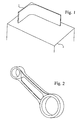
- Fig. 2 discloses an example of a piece for an engine, in this case a piston rod manufactured directly from a blank of MMC material which has been machined to its final shape as a piston rod according to the figure by means of high speed machining according to the invention.
- the cost for producing a piston rod according to Fig. 2 and made in MMC material is low at the same time as it shows the following advantages compared to piston rods made from other materials:
- the good results have been achieved by use of cutting tools made from coated hard metal with interior channel cooling and by use of diamond tools.
- diamond tools By use of diamond tools the worn out times for the tools are long up to 40% carbide content of the MMC material. When the carbide content is as high as 70%, good results were still achieved.
- the method according to the invention is applicable on all types of components which are to be manufactured from an MMC material, where machining is possible with respect to the final shape of the component.
- the method is thus not limited to the disclosed examples but may be used for all components, where a choice of MMC is advantageous.
- Some examples that may be mentioned are engine parts, mechanical structures for spacecrafts, mechanics for instruments, brake discs for vehicles, and the like.
- brake discs fabricated from MMC are advantageous in view of the low weight in comparison with steel, which contribute to decrease the rotational energy stored in the brake discs before a retardation, a condition that has a certain importance on trains, where each wheel shaft often is provided with a number of rotating brake discs made by steel.
Landscapes
- Chemical & Material Sciences (AREA)
- Engineering & Computer Science (AREA)
- Mechanical Engineering (AREA)
- Chemical Kinetics & Catalysis (AREA)
- Materials Engineering (AREA)
- Metallurgy (AREA)
- Organic Chemistry (AREA)
- Manufacture Of Alloys Or Alloy Compounds (AREA)
- Cutting Tools, Boring Holders, And Turrets (AREA)
- Shafts, Cranks, Connecting Bars, And Related Bearings (AREA)
- Milling Processes (AREA)
- Drilling And Boring (AREA)
Claims (23)
- Méthode de fabrication d'un composant d'une forme prédéfinie, fabriqué à partir d'un matériau composite à matrice métallique (CMM), qui englobe l'usinage d'une ébauche à grande vitesse du matériau CMM pour obtenir la forme prédéfinie du composant, le matériau CMM ici utilisé se caractérisant par une teneur en renforcements de 15 à 70 %, et l'état d'usinage HSM prédominant lorsque les forces de cisaillement diminuent au fur et à meure qu'augmente la vitesse de coupe.
- Méthode selon la revendication 1, dans laquelle l'état HSM prédomine lorsque la force de cisaillement, qui est fonction de la vitesse de coupe, passe à un maximum global.
- Méthode selon la revendication 1, dans laquelle l'outil de coupe comprend un membre prélevé du groupe comprenant un tranchant en métal dur enrobé, un tranchant en nitrure de bore et un tranchant diamanté.
- Méthode selon la revendication 2, dans laquelle l'outil de coupe comprend un membre prélevé du groupe comprenant un tranchant en métal dur enrobé, un tranchant en nitrure de bore et un tranchant diamanté.
- Méthode selon la revendication 4, dans laquelle le matériau CMM à usiner a une teneur en renforcements de 15 à 70 % environ.
- Méthode selon la revendication 3, dans laquelle le matériau CMM à usiner a une teneur en renforcements de 15 à 70 % environ.
- Méthode selon la revendication 6, dans laquelle ledit renforcement est au moins un membre du groupe composé de carbure de silicium, de carbure de bore et d'oxyde d'aluminium.
- Méthode selon la revendication 5, dans laquelle ledit renforcement est au moins un membre du groupe composé de carbure de silicium, de carbure de bore et d'oxyde d'aluminium.
- Méthode selon la revendication 5, dans laquelle ledit renforcement est un carbure.
- Méthode selon la revendication 6, dans laquelle ledit renforcement est un carbure.
- Méthode selon la revendication 5, dans laquelle le CMM comprend au moins une substance de base prélevée du groupe composé d'aluminium, de titane et d'alliages de ces métaux.
- Méthode selon la revendication 6, dans laquelle le CMM comprend au moins une substance de base prélevée du groupe composé d'aluminium, de titane et d'alliages de ces métaux.
- Méthode selon la revendication 1, dans laquelle le composant est un composant destiné à des véhicules motorisés ou à être utilisé dans des systèmes optiques.
- Méthode selon la revendication 13, dans laquelle le composant est une pièce de moteur banalisée.
- Méthode selon la revendication 13, dans laquelle le composant est une tige de piston ou un vilebrequin.
- Méthode selon la revendication 1, dans laquelle le composant est un composant pour véhicules roulant sur rails, poids lourds ou voitures.
- Méthode selon la revendication 16, dans laquelle le composant est un disque de frein ou un sabot de frein.
- Méthode selon la revendication 2, dans laquelle le composant est un composant destiné à des véhicules motorisés ou à être utilisé dans des systèmes optiques.
- Méthode selon la revendication 18, dans laquelle le composant est une pièce de moteur banalisée.
- Méthode selon la revendication 18, dans laquelle le composant est une tige de piston ou un vilebrequin.
- Méthode selon la revendication 2, dans laquelle le composant est un composant pour véhicules roulant sur rails, poids lourds ou voitures.
- Méthode selon la revendication 1, dans laquelle les forces de cisaillement, en fonction de la vitesse de coupe, tendent asymptotiquement vers zéro.
- Méthode selon la revendication 1, dans laquelle la vitesse de l'outil de coupe, qui exécute l'usinage de l'ébauche à hauteur d'un point de coupe associé à l'ébauche, est telle qu'un copeau formé à l'issue de l'usinage flotte, tout au moins momentanément, au point de découpe.
Priority Applications (1)
| Application Number | Priority Date | Filing Date | Title |
|---|---|---|---|
| EP03077985A EP1380374B1 (fr) | 1998-11-17 | 1999-11-05 | Usinage grande vitesse de matériau à matrice métallique |
Applications Claiming Priority (5)
| Application Number | Priority Date | Filing Date | Title |
|---|---|---|---|
| SE9803946 | 1998-11-17 | ||
| SE9803946A SE521289C2 (sv) | 1998-11-17 | 1998-11-17 | Bearbetning av metalmatriskompositmaterial (MMC) medelst höghastighetsbearbetning (HSM) |
| US207142 | 1998-12-08 | ||
| US09/207,142 US6102635A (en) | 1998-11-17 | 1998-12-08 | Machining of MMC material |
| PCT/SE1999/002007 WO2000029151A1 (fr) | 1998-11-17 | 1999-11-05 | Usinage grande vitesse de materiau a matrice metallique |
Related Child Applications (1)
| Application Number | Title | Priority Date | Filing Date |
|---|---|---|---|
| EP03077985A Division EP1380374B1 (fr) | 1998-11-17 | 1999-11-05 | Usinage grande vitesse de matériau à matrice métallique |
Publications (2)
| Publication Number | Publication Date |
|---|---|
| EP1140407A1 EP1140407A1 (fr) | 2001-10-10 |
| EP1140407B1 true EP1140407B1 (fr) | 2004-01-21 |
Family
ID=26663438
Family Applications (1)
| Application Number | Title | Priority Date | Filing Date |
|---|---|---|---|
| EP99972138A Expired - Lifetime EP1140407B1 (fr) | 1998-11-17 | 1999-11-05 | Usinage grande vitesse de materiau a matrice metallique |
Country Status (8)
| Country | Link |
|---|---|
| US (1) | US6293741B1 (fr) |
| EP (1) | EP1140407B1 (fr) |
| JP (1) | JP2003522030A (fr) |
| AT (2) | ATE297280T1 (fr) |
| DE (2) | DE69925766T2 (fr) |
| ES (1) | ES2214917T3 (fr) |
| RU (1) | RU2263007C2 (fr) |
| WO (1) | WO2000029151A1 (fr) |
Families Citing this family (4)
| Publication number | Priority date | Publication date | Assignee | Title |
|---|---|---|---|---|
| US7052637B1 (en) | 2000-05-17 | 2006-05-30 | Saab Ab | Manufacturing of components for valve mechanisms for internal combustion engines |
| DE60031003T2 (de) * | 2000-05-17 | 2007-02-08 | Saab Ab | Verfahren zur herstellung einer lagerverstärkung in leichtmetallgehäusen |
| WO2005070614A1 (fr) * | 2004-01-21 | 2005-08-04 | Toyohashi University Of Technology | Procede de formation de couche cristalline ultrafine, composant de machine dote d'une telle couche ainsi formee, procede de production du composant de machine, procede de formation de couche nano-cristalline, composant de machine dote d'une telle couche ainsi formee |
| JP7236108B2 (ja) * | 2020-04-17 | 2023-03-09 | 国立大学法人東海国立大学機構 | ミリング装置、及びミリング方法 |
Family Cites Families (22)
| Publication number | Priority date | Publication date | Assignee | Title |
|---|---|---|---|---|
| US4682744A (en) * | 1985-04-08 | 1987-07-28 | Rca Corporation | Spacecraft structure |
| US5015290A (en) * | 1988-01-22 | 1991-05-14 | The Dow Chemical Company | Ductile Ni3 Al alloys as bonding agents for ceramic materials in cutting tools |
| US4908923A (en) * | 1988-10-05 | 1990-03-20 | Ford Motor Company | Method of dimensionally stabilizing interface between dissimilar metals in an internal combustion engine |
| US4955135A (en) * | 1988-11-16 | 1990-09-11 | Vapor Technologies Inc. | Method of making matrix composites |
| US5392263A (en) * | 1990-01-31 | 1995-02-21 | Sony Corporation | Magneto-optical disk system with specified thickness for protective layer on the disk relative to the numerical aperture of the objective lens |
| US5570502A (en) * | 1991-04-08 | 1996-11-05 | Aluminum Company Of America | Fabricating metal matrix composites containing electrical insulators |
| JP2666007B2 (ja) * | 1991-06-20 | 1997-10-22 | ジーエヌツール株式会社 | ニック付切削工具 |
| GB9121107D0 (en) * | 1991-10-04 | 1991-11-20 | British Aerospace | Improvements relating to diffusion bonded/superplastically formed cellular structures |
| US5348431A (en) * | 1991-10-09 | 1994-09-20 | Canon Kabushiki Kaisha | Precision cutting process machine and precision cutting process method |
| CA2102427C (fr) * | 1992-04-28 | 1998-02-10 | Manuel Carl Turchan | Fraisage en bout adiabatique |
| JPH06218521A (ja) * | 1993-01-26 | 1994-08-09 | Unisia Jecs Corp | 内燃機関のピストン |
| US5511603A (en) * | 1993-03-26 | 1996-04-30 | Chesapeake Composites Corporation | Machinable metal-matrix composite and liquid metal infiltration process for making same |
| US5702542A (en) * | 1993-03-26 | 1997-12-30 | Brown; Alexander M. | Machinable metal-matrix composite |
| US5415500A (en) * | 1993-10-04 | 1995-05-16 | Rockwell International Corp. | Method of drilling holes in reinforced metal matrix composites |
| WO1995026246A1 (fr) * | 1994-03-29 | 1995-10-05 | Niles-Simmons Industrieanlagen Gmbh | Outil de profilage et procede d'usinage d'essieux montes par enlevement de matiere |
| US5758999A (en) * | 1994-07-21 | 1998-06-02 | Geise; Samuel C. | Hydraulically powered spindle for working metals and composite materials |
| US5518346A (en) * | 1994-07-21 | 1996-05-21 | Geise; Samuel C. | High-speed hydrodynamic spindle and method for machining composite and specialized metallic materials |
| DE19505724A1 (de) | 1995-02-20 | 1996-08-29 | Daimler Benz Ag | Aluminium-Bremsscheibe |
| JPH09170487A (ja) * | 1995-05-26 | 1997-06-30 | Toyota Motor Corp | シリンダブロックの製造方法 |
| JP3377665B2 (ja) * | 1995-12-15 | 2003-02-17 | 新潟県 | エンドミル状工具による繊維質有機材料、硬脆性無機材料、ガラス質無機材料の切削加工法 |
| US5782324A (en) * | 1995-12-27 | 1998-07-21 | Dayton Walther Corporation | Composite brake drum and method for producing same |
| JPH11347807A (ja) * | 1998-06-03 | 1999-12-21 | Osaka Diamond Ind Co Ltd | 延性難削材用の切削工具並びに切削法 |
-
1999
- 1999-11-05 DE DE69925766T patent/DE69925766T2/de not_active Expired - Lifetime
- 1999-11-05 JP JP2000582177A patent/JP2003522030A/ja active Pending
- 1999-11-05 AT AT03077985T patent/ATE297280T1/de not_active IP Right Cessation
- 1999-11-05 ES ES99972138T patent/ES2214917T3/es not_active Expired - Lifetime
- 1999-11-05 RU RU2001116583/02A patent/RU2263007C2/ru active
- 1999-11-05 DE DE69914374T patent/DE69914374T2/de not_active Expired - Lifetime
- 1999-11-05 WO PCT/SE1999/002007 patent/WO2000029151A1/fr not_active Ceased
- 1999-11-05 EP EP99972138A patent/EP1140407B1/fr not_active Expired - Lifetime
- 1999-11-05 AT AT99972138T patent/ATE258093T1/de not_active IP Right Cessation
-
2000
- 2000-07-11 US US09/613,838 patent/US6293741B1/en not_active Expired - Lifetime
Also Published As
| Publication number | Publication date |
|---|---|
| RU2263007C2 (ru) | 2005-10-27 |
| DE69925766T2 (de) | 2006-03-23 |
| DE69914374D1 (de) | 2004-02-26 |
| ATE297280T1 (de) | 2005-06-15 |
| DE69925766D1 (de) | 2005-07-14 |
| EP1140407A1 (fr) | 2001-10-10 |
| JP2003522030A (ja) | 2003-07-22 |
| ES2214917T3 (es) | 2004-09-16 |
| WO2000029151A1 (fr) | 2000-05-25 |
| DE69914374T2 (de) | 2004-12-09 |
| US6293741B1 (en) | 2001-09-25 |
| ATE258093T1 (de) | 2004-02-15 |
Similar Documents
| Publication | Publication Date | Title |
|---|---|---|
| Looney et al. | The turning of an Al/SiC metal-matrix composite | |
| Schulz et al. | High-speed machining | |
| Adibi et al. | Study on minimum quantity lubrication (MQL) in grinding of carbon fiber-reinforced SiC matrix composites (CMCs) | |
| JP3323827B2 (ja) | 精密部品の製造方法 | |
| Klocke et al. | Broaching of Inconel 718 with cemented carbide | |
| Grzesik | Machining of hard materials | |
| US7052637B1 (en) | Manufacturing of components for valve mechanisms for internal combustion engines | |
| Jackson | Recent advances in ultraprecision abrasive machining processes | |
| EP1140407B1 (fr) | Usinage grande vitesse de materiau a matrice metallique | |
| EP1380374B1 (fr) | Usinage grande vitesse de matériau à matrice métallique | |
| US6779245B1 (en) | Bearing reinforcement in light metal housing | |
| Handa et al. | Performance assessment of a hybrid intermittent-progressive grinding strategy for bi-directional carbon fibre reinforced composites | |
| Choragudi et al. | Investigation of the machining of titanium components in lightweight vehicles | |
| Čerče et al. | Increasing machinability of grey cast iron using cubic boron nitride tools: evaluation of wear mechanisms | |
| Reddy et al. | Studies on tool wear, cutting forces and chip morphology during high-speed milling of Al-Si-Mg-Fe Alloys | |
| WO2001088219A1 (fr) | Piece de moteur a surface enduite et procede de production correspondant | |
| Ebbrell | Process requirements for precision grinding | |
| RU2001116583A (ru) | Способ высокоскоростной механической обработки (вмо) композиционного материала с металлической матрицей (кмм) | |
| EP2406037A1 (fr) | Procédé de finition d'alésages, outil d'usinage et machine d'usinage associée, ainsi que pièce | |
| Bhuigad et al. | A Review on Grinding Machining for Al Composites | |
| Olofson et al. | Machining of Superalloys and Refractory Metals | |
| Ronald et al. | Grinding of Metal Matrix Composites | |
| Clark | The use of polycrystalline diamond (PCD) for machining highly abrasive workpiece materials | |
| Kim et al. | CBN see—ois-ca seen/as asaa salute as | |
| Klocke et al. | Tool Life Behaviour |
Legal Events
| Date | Code | Title | Description |
|---|---|---|---|
| PUAI | Public reference made under article 153(3) epc to a published international application that has entered the european phase |
Free format text: ORIGINAL CODE: 0009012 |
|
| 17P | Request for examination filed |
Effective date: 20010618 |
|
| AK | Designated contracting states |
Kind code of ref document: A1 Designated state(s): AT BE CH CY DE DK ES FI FR GB GR IE IT LI LU MC NL PT SE |
|
| 17Q | First examination report despatched |
Effective date: 20011015 |
|
| GRAH | Despatch of communication of intention to grant a patent |
Free format text: ORIGINAL CODE: EPIDOS IGRA |
|
| RIN1 | Information on inventor provided before grant (corrected) |
Inventor name: EKBLAD, STEFAN Inventor name: KARLSSON, SVEN-AKE Inventor name: STRAND, KENT |
|
| GRAS | Grant fee paid |
Free format text: ORIGINAL CODE: EPIDOSNIGR3 |
|
| GRAA | (expected) grant |
Free format text: ORIGINAL CODE: 0009210 |
|
| AK | Designated contracting states |
Kind code of ref document: B1 Designated state(s): AT BE CH CY DE DK ES FI FR GB GR IE IT LI LU MC NL PT SE |
|
| PG25 | Lapsed in a contracting state [announced via postgrant information from national office to epo] |
Ref country code: NL Free format text: LAPSE BECAUSE OF FAILURE TO SUBMIT A TRANSLATION OF THE DESCRIPTION OR TO PAY THE FEE WITHIN THE PRESCRIBED TIME-LIMIT Effective date: 20040121 Ref country code: LI Free format text: LAPSE BECAUSE OF FAILURE TO SUBMIT A TRANSLATION OF THE DESCRIPTION OR TO PAY THE FEE WITHIN THE PRESCRIBED TIME-LIMIT Effective date: 20040121 Ref country code: FI Free format text: LAPSE BECAUSE OF FAILURE TO SUBMIT A TRANSLATION OF THE DESCRIPTION OR TO PAY THE FEE WITHIN THE PRESCRIBED TIME-LIMIT Effective date: 20040121 Ref country code: CY Free format text: LAPSE BECAUSE OF FAILURE TO SUBMIT A TRANSLATION OF THE DESCRIPTION OR TO PAY THE FEE WITHIN THE PRESCRIBED TIME-LIMIT Effective date: 20040121 Ref country code: CH Free format text: LAPSE BECAUSE OF FAILURE TO SUBMIT A TRANSLATION OF THE DESCRIPTION OR TO PAY THE FEE WITHIN THE PRESCRIBED TIME-LIMIT Effective date: 20040121 Ref country code: BE Free format text: LAPSE BECAUSE OF FAILURE TO SUBMIT A TRANSLATION OF THE DESCRIPTION OR TO PAY THE FEE WITHIN THE PRESCRIBED TIME-LIMIT Effective date: 20040121 Ref country code: AT Free format text: LAPSE BECAUSE OF FAILURE TO SUBMIT A TRANSLATION OF THE DESCRIPTION OR TO PAY THE FEE WITHIN THE PRESCRIBED TIME-LIMIT Effective date: 20040121 |
|
| REG | Reference to a national code |
Ref country code: GB Ref legal event code: FG4D |
|
| REG | Reference to a national code |
Ref country code: CH Ref legal event code: EP |
|
| REG | Reference to a national code |
Ref country code: IE Ref legal event code: FG4D |
|
| REF | Corresponds to: |
Ref document number: 69914374 Country of ref document: DE Date of ref document: 20040226 Kind code of ref document: P |
|
| PG25 | Lapsed in a contracting state [announced via postgrant information from national office to epo] |
Ref country code: SE Free format text: LAPSE BECAUSE OF FAILURE TO SUBMIT A TRANSLATION OF THE DESCRIPTION OR TO PAY THE FEE WITHIN THE PRESCRIBED TIME-LIMIT Effective date: 20040421 Ref country code: GR Free format text: LAPSE BECAUSE OF FAILURE TO SUBMIT A TRANSLATION OF THE DESCRIPTION OR TO PAY THE FEE WITHIN THE PRESCRIBED TIME-LIMIT Effective date: 20040421 Ref country code: DK Free format text: LAPSE BECAUSE OF FAILURE TO SUBMIT A TRANSLATION OF THE DESCRIPTION OR TO PAY THE FEE WITHIN THE PRESCRIBED TIME-LIMIT Effective date: 20040421 |
|
| NLV1 | Nl: lapsed or annulled due to failure to fulfill the requirements of art. 29p and 29m of the patents act | ||
| REG | Reference to a national code |
Ref country code: CH Ref legal event code: PL |
|
| REG | Reference to a national code |
Ref country code: ES Ref legal event code: FG2A Ref document number: 2214917 Country of ref document: ES Kind code of ref document: T3 |
|
| ET | Fr: translation filed | ||
| PG25 | Lapsed in a contracting state [announced via postgrant information from national office to epo] |
Ref country code: LU Free format text: LAPSE BECAUSE OF NON-PAYMENT OF DUE FEES Effective date: 20041105 Ref country code: IE Free format text: LAPSE BECAUSE OF NON-PAYMENT OF DUE FEES Effective date: 20041105 |
|
| PLBE | No opposition filed within time limit |
Free format text: ORIGINAL CODE: 0009261 |
|
| STAA | Information on the status of an ep patent application or granted ep patent |
Free format text: STATUS: NO OPPOSITION FILED WITHIN TIME LIMIT |
|
| PG25 | Lapsed in a contracting state [announced via postgrant information from national office to epo] |
Ref country code: MC Free format text: LAPSE BECAUSE OF NON-PAYMENT OF DUE FEES Effective date: 20041130 |
|
| 26N | No opposition filed |
Effective date: 20041022 |
|
| REG | Reference to a national code |
Ref country code: IE Ref legal event code: MM4A |
|
| PG25 | Lapsed in a contracting state [announced via postgrant information from national office to epo] |
Ref country code: PT Free format text: LAPSE BECAUSE OF NON-PAYMENT OF DUE FEES Effective date: 20040621 |
|
| REG | Reference to a national code |
Ref country code: DE Ref legal event code: R082 Ref document number: 69914374 Country of ref document: DE Representative=s name: PATENTANWAELTE HENKEL, BREUER & PARTNER, DE |
|
| REG | Reference to a national code |
Ref country code: FR Ref legal event code: PLFP Year of fee payment: 17 |
|
| REG | Reference to a national code |
Ref country code: FR Ref legal event code: PLFP Year of fee payment: 18 |
|
| REG | Reference to a national code |
Ref country code: FR Ref legal event code: PLFP Year of fee payment: 19 |
|
| PGFP | Annual fee paid to national office [announced via postgrant information from national office to epo] |
Ref country code: DE Payment date: 20181119 Year of fee payment: 20 |
|
| PGFP | Annual fee paid to national office [announced via postgrant information from national office to epo] |
Ref country code: IT Payment date: 20181123 Year of fee payment: 20 Ref country code: GB Payment date: 20181116 Year of fee payment: 20 Ref country code: ES Payment date: 20181203 Year of fee payment: 20 |
|
| PGFP | Annual fee paid to national office [announced via postgrant information from national office to epo] |
Ref country code: FR Payment date: 20181121 Year of fee payment: 20 |
|
| REG | Reference to a national code |
Ref country code: DE Ref legal event code: R071 Ref document number: 69914374 Country of ref document: DE |
|
| REG | Reference to a national code |
Ref country code: GB Ref legal event code: PE20 Expiry date: 20191104 |
|
| PG25 | Lapsed in a contracting state [announced via postgrant information from national office to epo] |
Ref country code: GB Free format text: LAPSE BECAUSE OF EXPIRATION OF PROTECTION Effective date: 20191104 |
|
| REG | Reference to a national code |
Ref country code: ES Ref legal event code: FD2A Effective date: 20200805 |
|
| PG25 | Lapsed in a contracting state [announced via postgrant information from national office to epo] |
Ref country code: ES Free format text: LAPSE BECAUSE OF EXPIRATION OF PROTECTION Effective date: 20191106 |