EP1139572A1 - Interleave address generating device and interleave address generating method - Google Patents
Interleave address generating device and interleave address generating method Download PDFInfo
- Publication number
- EP1139572A1 EP1139572A1 EP00964709A EP00964709A EP1139572A1 EP 1139572 A1 EP1139572 A1 EP 1139572A1 EP 00964709 A EP00964709 A EP 00964709A EP 00964709 A EP00964709 A EP 00964709A EP 1139572 A1 EP1139572 A1 EP 1139572A1
- Authority
- EP
- European Patent Office
- Prior art keywords
- interleave
- addresses
- data
- address
- variable
- Prior art date
- Legal status (The legal status is an assumption and is not a legal conclusion. Google has not performed a legal analysis and makes no representation as to the accuracy of the status listed.)
- Withdrawn
Links
Images






Classifications
-
- H—ELECTRICITY
- H03—ELECTRONIC CIRCUITRY
- H03M—CODING; DECODING; CODE CONVERSION IN GENERAL
- H03M13/00—Coding, decoding or code conversion, for error detection or error correction; Coding theory basic assumptions; Coding bounds; Error probability evaluation methods; Channel models; Simulation or testing of codes
-
- H—ELECTRICITY
- H03—ELECTRONIC CIRCUITRY
- H03M—CODING; DECODING; CODE CONVERSION IN GENERAL
- H03M13/00—Coding, decoding or code conversion, for error detection or error correction; Coding theory basic assumptions; Coding bounds; Error probability evaluation methods; Channel models; Simulation or testing of codes
- H03M13/27—Coding, decoding or code conversion, for error detection or error correction; Coding theory basic assumptions; Coding bounds; Error probability evaluation methods; Channel models; Simulation or testing of codes using interleaving techniques
- H03M13/2771—Internal interleaver for turbo codes
-
- H—ELECTRICITY
- H03—ELECTRONIC CIRCUITRY
- H03M—CODING; DECODING; CODE CONVERSION IN GENERAL
- H03M13/00—Coding, decoding or code conversion, for error detection or error correction; Coding theory basic assumptions; Coding bounds; Error probability evaluation methods; Channel models; Simulation or testing of codes
- H03M13/27—Coding, decoding or code conversion, for error detection or error correction; Coding theory basic assumptions; Coding bounds; Error probability evaluation methods; Channel models; Simulation or testing of codes using interleaving techniques
- H03M13/2703—Coding, decoding or code conversion, for error detection or error correction; Coding theory basic assumptions; Coding bounds; Error probability evaluation methods; Channel models; Simulation or testing of codes using interleaving techniques the interleaver involving at least two directions
-
- H—ELECTRICITY
- H03—ELECTRONIC CIRCUITRY
- H03M—CODING; DECODING; CODE CONVERSION IN GENERAL
- H03M13/00—Coding, decoding or code conversion, for error detection or error correction; Coding theory basic assumptions; Coding bounds; Error probability evaluation methods; Channel models; Simulation or testing of codes
- H03M13/27—Coding, decoding or code conversion, for error detection or error correction; Coding theory basic assumptions; Coding bounds; Error probability evaluation methods; Channel models; Simulation or testing of codes using interleaving techniques
- H03M13/2703—Coding, decoding or code conversion, for error detection or error correction; Coding theory basic assumptions; Coding bounds; Error probability evaluation methods; Channel models; Simulation or testing of codes using interleaving techniques the interleaver involving at least two directions
- H03M13/271—Row-column interleaver with permutations, e.g. block interleaving with inter-row, inter-column, intra-row or intra-column permutations
-
- H—ELECTRICITY
- H03—ELECTRONIC CIRCUITRY
- H03M—CODING; DECODING; CODE CONVERSION IN GENERAL
- H03M13/00—Coding, decoding or code conversion, for error detection or error correction; Coding theory basic assumptions; Coding bounds; Error probability evaluation methods; Channel models; Simulation or testing of codes
- H03M13/27—Coding, decoding or code conversion, for error detection or error correction; Coding theory basic assumptions; Coding bounds; Error probability evaluation methods; Channel models; Simulation or testing of codes using interleaving techniques
- H03M13/2735—Interleaver using powers of a primitive element, e.g. Galois field [GF] interleaver
Definitions
- the present invention relates to an interleave address generation apparatus and interleave address generation method, and more particularly, to an interleave address generation apparatus and interleave address generation method ideally applicable to a communication terminal apparatus or base station apparatus.
- the GF interleave sequentially rearranges bits (hereinafter referred to as "column exchange") of a bit string of M bits in length delimited row by row from the first row to Nth row in different sequences, and generates an interleave address pattern by reading the matrix subjected to the row exchange carried out according to the sequence based on a bit inversion method from the first row of the first column from top to bottom to the Nth row of the Mth column.
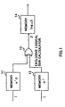
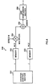
- FIG.1 is a block diagram showing a configuration of a column exchange apparatus used for a conventional GF interleave.
- memory 11 outputs vector ⁇ i0 corresponding to row number i (0 ⁇ i ⁇ N) input to exclusive logical sum calculator 13.
- Memory 12 outputs vector ⁇ j corresponding to column number j (0 ⁇ j ⁇ M) input to exclusive logical sum calculator 13.
- Exclusive logical sum calculator 13 calculates an exclusive logical sum of ⁇ j0 and ⁇ j and outputs calculation result ⁇ to memory 14.
- Memory 14 outputs column conversion pattern ⁇ i(j) for the ith row based on calculation result ⁇ .
- ⁇ i(j) is calculated from following expression (1).
- FIG.2 shows a conversion table used for the GF interleave.
- the conversion table in FIG.2 is a table that shows correspondences between power in a Galois field power expression and a vector expression with the Galois field polynomial basis.
- the vector expression consists of vectors output from memory 11 and memory 12 and vectors input to memory 14.
- Power log ⁇ ⁇ in a power expression is a value input to memory 11 or memory 12 and a value output from memory 14.
- the column conversion pattern on the ith row is obtained through the operation shown below.
- vector ⁇ i0 corresponding to parameter i0 is output.
- Exclusive logical sum calculator 13 calculates an exclusive logical sum of ⁇ i0 and ⁇ j output from memory 11 and memory 12 and memory 14 outputs log ⁇ ⁇ corresponding to calculation result ⁇ .
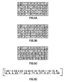
- FIG.3A, FIG.3B, FIG.3C and FIG.3D illustrate the process of generation of interleave addresses.
- the interleave address generation apparatus adds an offset address to the stored value in row units. More specifically, a value obtained by multiplying the value of i by the number of column components is added to the value of i. For example, value 16 obtained by multiplying 2, the value of i, by 8, the number of components, is added to values on the 2nd column respectively. Value 8 obtained by multiplying 1, the value of i, by 8, the number of components, is added to values on the 3rd column respectively. Value 24 obtained by multiplying 3, the value of i, by 8, the number of components, is added to values on the 4th column respectively. The addition result is shown in FIG.3C.
- the conventional interleave address generation method develops an interleave address pattern created in predetermined units in memory and then performs row rearrangement and an addition of offset addresses, and thus the conventional interleave address generation method has a problem that a considerable memory space and considerable processing time are required to generate an interleave address pattern.
- This object is attained by simultaneously carrying out row rearrangement processing and column rearrangement processing during generation of interleave addresses and continuously carrying out this row rearrangement processing and column rearrangement processing and offset address addition processing to create interleave addresses.
- the interleave address generation apparatus carries out row rearrangement processing and column rearrangement processing in parallel.
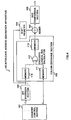
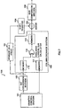
- FIG.4 is a block diagram showing a configuration of the interleave address generation apparatus according to Embodiment 1 of the present invention.
- Interleave address generation apparatus 100 shown in FIG.4 is mainly constructed of counter control section 101, bit inversion apparatus 102, column conversion apparatus 103, shift register 104, adder 105 and size comparison section 106.
- column conversion apparatus 103 is mainly constructed of memory 110, memory 111, memory 113 and exclusive logical sum calculator 112.
- counter control section 101 outputs row number i (0 ⁇ i ⁇ 2 2 ) on a two-dimensional array to bit inversion apparatus 102 and column number j (0 ⁇ j ⁇ 2 3 ) on a two-dimensional array to memory 111.
- Bit inversion apparatus 102 carries out bit inversion of row number i output from counter control section 101 in a binary state and outputs bit-inverted row number i' to memory 110 and shift register 104. More specifically, bit inversion apparatus 102 switches between the higher digit and the lower digit of the binary coded row number. That is, bit inversion apparatus 102 switches the highest digit and lowest digit, then switches between the 2nd highest digit and the 2nd lowest digit. And this same switching between a higher digit and lower digit is continued.
- Memory 110 stores values resulting from assigning different i0's to ⁇ i0 on respective rows, calculates i0 corresponding to i' input and outputs ⁇ i0 corresponding to i0 to exclusive logical sum calculator 112.
- Memory 111 stores values resulting from assigning different j's to ⁇ j (0 ⁇ j ⁇ M) on respective rows and outputs ⁇ j corresponding to j input to exclusive logical sum calculator 112.
- Exclusive logical sum calculator 112 calculates an exclusive logical sum of ⁇ i0 output from memory 110 and ⁇ j output from memory 111 and outputs the calculation result to memory 113.
- Memory 113 stores the column conversion pattern corresponding to the calculation result of exclusive logical sum calculator 112 and outputs the column conversion pattern corresponding to the calculation result input to adder 105.
- Shift register 104 bit-shifts the value output from bit inversion apparatus 102 and outputs this to adder 105 as an address offset value.
- Adder 105 adds up the output from shift register 104 and the output from column conversion apparatus 103 and outputs the addition result to size comparison section 106.
- Size comparison section 106 compares the addition result output from adder 105 with the interleave size and outputs the addition result which is not greater than the interleave size as an address value.
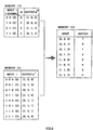
- FIG.5 illustrates a data configuration example in an exclusive logical sum calculation of this embodiment.
- Memory 110 stores parameter i0 corresponding to row number i in correspondence with 3-bit vector ⁇ i0 and outputs 3-bit vector ⁇ i0 corresponding to i0 input.
- Memory 111 stores parameter j corresponding to row number i in correspondence with ⁇ j and outputs 3-bit vector ⁇ j corresponding to j input.
- Exclusive logical sum calculator 112 carries out an exclusive logical sum of vector ⁇ i0 and vector ⁇ j and outputs calculation result ⁇ to memory 113.
- Memory 113 outputs the column-rearranged data corresponding to calculation result ⁇ .
- FIG.6 shows an example of creation of interleave addresses.
- i and j denote a row number and column number output from counter control section 101 and i' denotes a row number output from bit inversion apparatus 102.
- ⁇ i0 and ⁇ j denote vector data output from memory 110 and memory 111 and ⁇ i0 + ⁇ j denotes the calculation result in exclusive logical sum calculator 112.
- Log ⁇ ⁇ i0 + ⁇ j denotes data output from memory 113 and the offset addition result denotes the result of the addition of an offset address output from shift register 104.
- Data processing is carried out on one row at a time starting from the top row.
- Bit inversion apparatus 102 outputs row number i after switching between the higher digit and lower digit of the row number bits in a binary state.
- Memory 110 outputs ⁇ i0 corresponding to row number i'.
- ⁇ i0 (1,0,0) is output.
- Memory 111 outputs ⁇ j corresponding to row number j.
- ⁇ j (1,0,0) is output.
- Exclusive logical sum calculator 112 calculates an exclusive logical sum of ⁇ i0 output from memory 110 and ⁇ j output from memory 111.
- ⁇ i0 + ⁇ j (0,0,0) is output.
- Memory 113 outputs column-rearranged data log ⁇ ( ⁇ i0 + ⁇ j ) corresponding to calculation result ⁇ i0 + ⁇ j output from exclusive logical sum calculator 112.
- ⁇ i0 + ⁇ j (0,0,0)
- "4" is output as the column-rearranged data.
- Adder 105 adds a value obtained by multiplying the total number of column number j by i' to the column-rearranged data and outputs the addition result.
- the interleave address generation apparatus controls so that i is reset every time i exceeds a maximum value and in this way sequentially outputs addresses for a 2 2 ⁇ 2 3 two-dimensional array in the column direction. Furthermore, the interleave address generation apparatus uses output i' from bit inversion apparatus 102 as the read address value for memory 110, and can thereby carry out row exchange on the aforementioned two-dimensional array simultaneously.
- the interleave address generation apparatus outputs row numbers and column numbers individually and converts numbers individually, and can thereby carry out row rearrangement processing and column rearrangement processing in parallel, allowing an interleave address pattern to be generated in a small space and short processing time.
- FIG.7 is a block diagram showing a configuration example of an interleave address generation apparatus according to Embodiment 2.
- the configuration common to that in FIG.4 is assigned the same reference numerals as those in FIG.4 and detailed explanations thereof are omitted.
- Interleave address generation apparatus 150 in FIG.7 is different from FIG.4 in that interleave address generation apparatus 150 is equipped with storage cell array 151 and adds up offset addresses according to the output timing from memory 113.
- storage cell array 151 temporarily stores row number i' output from bit inversion apparatus 102 and then outputs row number i' to shift register 104.
- storage cell array 151 is constructed of a two-stage storage cell array to adjust the timings of the output from column conversion apparatus 103 and the output from shift register 104 to the timing of the output value i' from bit inversion apparatus 102.
- output value i' from bit inversion apparatus 102 is temporarily stored in storage cell array 151, sequentially output in synchronization with the addition timing of adder 105, input to shift register 104 and a value resulting from shifting 3 bits is output as an address offset value for the i'th row.
- the interleave address generation apparatus outputs row numbers and column numbers individually and converts numbers individually, and can thereby carry out row rearrangement processing and column rearrangement processing in parallel, allowing an interleave address pattern to be generated in a small space and short processing time.
- the interleave address generation apparatus can adjust the output timing of the adder by delaying the output timing of an offset address value using a temporary storage circuit, making it possible to generate an interleave address pattern even when the speed of generation of an offset address value is different from that of a column exchange pattern.
- FIG.8 is a block diagram showing a configuration example of an interleave address generation apparatus according to Embodiment 3.
- counter control section 201 outputs row number i of a two-dimensional array to memory 202 and outputs column number j of a two-dimensional array to memory 203.
- Memory 202 stores N(i) corresponding to input i and outputs N(i) corresponding to i output from counter control section 201 to multiplier 204.
- Memory 203 stores M(j) corresponding to input j and outputs M(j) corresponding to j output from counter control section 201 to adder 205.
- Multiplier 204 multiplies N(i) output from memory 202 by the number of columns M and outputs the multiplication result to adder 205.
- Adder 205 adds the multiplication result output from multiplier 204 to M(j) output from memory 203 and outputs the addition result to size comparison section 206.
- size comparison section 206 When the addition result output from adder 205 is smaller than the size of the required interleave address, size comparison section 206 outputs the addition result as the interleave address and when the addition result is equal to or greater than the size of the required interleave address, size comparison section 206 does not output the addition result.
- FIG.9 shows a table example stored in memory 202.
- N(i) is an output corresponding to input i and i has a one-to-one correspondence with N(i) and N(i)s corresponding to different i's take mutually different values.
- FIG. 10 illustrates a table example stored in memory 203.
- M(j) is an output corresponding to input j and j has a one-to-one correspondence with M(j) and M(j)s corresponding to different j's take mutually different values.
- FIG.11A illustrates an example of row number i and column number j output from counter control section 201.
- FIG.11B illustrates an example of converted row numbers and column numbers.
- Row number i output from counter control section 201 is converted to N(i) according to the table in FIG.9 and column number j is converted to M(j) according to the table in FIG.10.
- FIG.11C illustrates an example showing the addition result output from adder 205.
- Adder 205 outputs a value obtained by adding M(j) to a multiplication result of multiplying N(i) by the number of columns.
- adder 205 outputs 19, a value obtained by adding M(j) to a multiplication result of multiplying the number of columns 8 by N(i).
- Size comparison section 206 outputs addition results among other addition results in FIG.11C which are smaller than the requested interleave address size as the interleave addresses.
- FIG.11D illustrates an example of interleave addresses output from interleave address apparatus 200.
- the interleave address generation apparatus carries out row rearrangement processing and column rearrangement processing in parallel, and carries out this row rearrangement processing and column rearrangement processing and offset address addition processing continuously, allowing an interleave address pattern to be generated in a small space and short processing time.
- the interleave address generation apparatus can generate interleave addresses in a simpler configuration than Embodiment 1 or Embodiment 2 by using a same column exchange pattern on respective rows.
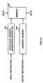
- FIG. 12 is a block diagram showing a configuration of an interleave apparatus according to Embodiment 4 of the present invention.
- interleave address generation apparatus 301 outputs an interleave address pattern to memory 303 according to an input instruction by which data is input to memory.
- Address counter 302 outputs addresses one by one starting from the start address in memory to memory 303 according to a data output instruction by which data is output.
- Memory 303 stores data sequentially at addresses output from interleave address generation apparatus 301, and after storing a predetermined amount of data, outputs address data output from address counter 302 sequentially.
- the interleave apparatus of this embodiment can perform high-speed interleave processing with small memory by rearranging information series using an interleave address pattern generated by the interleave address generation apparatus of Embodiment 1 or Embodiment 2.
- the interleave apparatus of Embodiment 4 stores data in memory of addresses output from interleave address generation apparatus 301 and reads data from memory of addresses output from address counter 302, but the present invention is not limited to this and it is also possible to store data in memory of addresses output from address counter 302, read data from memory of addresses output from interleave address generation apparatus 301 and rearrange data.
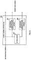
- FIG.13 is a block diagram showing a configuration of a turbo coding apparatus according to Embodiment 5 of the present invention.
- turbo coding apparatus 400 is mainly constructed of recursive convolutional coder 401, interleaver 402 and recursive convolutional coder 403.
- Recursive convolutional coder 401 performs convolutional code coding on an information series input and outputs the coded information series to the outside.
- Interleaver 402 is constructed of the interleave apparatus of Embodiment 4, performs interleave processing on the information series input and outputs the interleaved information series to recursive convolutional coder 403.
- Recursive convolutional coder 403 carries out convolutional code coding on the information series output from interleaver 402 and outputs the coded information series to the outside.
- turbo coding apparatus 400 Then, the operation of turbo coding apparatus 400 will be explained.
- the input information series is subjected to convolutional coding by recursive convolutional coder 401 and the coded information series is output.
- the input information series is subjected to data rearrangement by interleaver 402 and the rearranged information series is subjected to convolutional coding by recursive convolutional coder 403 and the coded information series is output.
- 3 bits are output as a code series corresponding to 1 information series bit: the output of the information series itself; the output from recursive convolutional coder 401 that performs coding of convolutional codes using the information series as an input; and the output of recursive convolutional coder 403 that performs coding of convolutional codes using data rearranged by interleaver 402 as an input which is the data written in memory before being input to recursive convolutional coder 403 using the information series as an input.
- turbo coding apparatus 400 outputs the information series input, the information series subjected to convolutional coding and the information series subjected to data rearrangement and convolutional coding.
- the turbo coding apparatus of this embodiment can speed up processing by rearranging information series using the interleave apparatus of Embodiment 4, and can thereby improve the error correcting performance.
- turbo coding apparatus 400 of Embodiment 5 it is possible to implement turbo coding apparatus 400 with improved error correcting performance for decoding of a code series on the receiving side by applying the interleave apparatus of Embodiment 4 according to the GF interleave system to interleaver 402.
- the turbo coding apparatus of this embodiment can speedily generate interleave addresses with small memory and perform interleave by rearranging the information series using the interleave apparatus of Embodiment 4, and can thereby perform turbo coding with small memory.
- FIG.14 is a block diagram showing a configuration of a turbo decoding apparatus according to Embodiment 6 of the present invention.
- turbo decoding apparatus 500 is mainly constructed of soft decision output decoder 501, interleaver 502, soft decision output decoder 503 and deinterleaver 504.
- Soft decision output decoder 501 decodes the code series input and outputs the input decoded code series to interleaver 502.
- Interleaver 502 rearranges the code series output from soft decision output decoder 501 and outputs to soft decision output decoder 503.
- Soft decision output decoder 503 decodes the code series output from interleaver 502 and outputs to deinterleaver 504.
- Deinterleaver 504 rearranges the code series output from soft decision output decoder 503 and outputs the obtained code series to soft decision output decoder 501 and the outside.
- turbo decoding apparatus 500 Then, the operation of turbo decoding apparatus 500 will be explained.
- the code series subjected to convolutional coding by the turbo coding apparatus, etc. of Embodiment 5 is decoded by soft decision output decoder 501 and the obtained soft decision output is output to interleaver 502.
- soft decision output from soft decision output decoder 501 is subjected to data series rearrangement by interleaver 502 and output to soft decision output decoder 503.
- the data series output from interleaver 502 is decoded together with the information series received by soft decision output decoder 503 and the soft decision output obtained is output to deinterleaver 504.
- the soft decision output from soft decision output decoder 503 is subjected to data series rearrangement by deinterleaver 504 and the rearranged data series is output to soft decision output decoder 501 and the outside.
- the data series output from deinterleaver 504 is output to soft decision output decoder 501 and used for the second and subsequent turbo decoding processing as reliability information.
- the code series subjected to convolutional coding is decoded by soft decision output decoder 501 using the data series output from deinterleaver 504 as reliability information and the soft decision output obtained is output to interleaver 502.
- the turbo decoding apparatus of this embodiment can speed up processing by rearranging the information series using the interleave apparatus of Embodiment 4, and can thereby improve the error correcting performance.
- turbo decoder 500 with improved error correcting performance by applying the interleave apparatus of Embodiment 4 to interleaver 502 and interleaver 504.
- the turbo decoding apparatus of this embodiment can reduce memory required for processing by rearranging information series using the interleave apparatus of Embodiment 4, and can thereby perform turbo coding with small memory.
- FIG.15 is a block diagram showing a configuration of a communication terminal apparatus according to Embodiment 7 of the present invention.
- communication terminal apparatus 600 is mainly constructed of antenna 601, reception section 602, transmission section 603, demodulation section 604, modulation section 605, decoding processing section 606, coding processing section 607, speech CODEC section 608, data input/output section 609, speaker 610 and microphone 611.
- Decoding processing section 606 is constructed of deinterleave section 614, rate matching section 615 and error correcting/decoding section 616.
- Coding processing section 607 is constructed of error correcting/coding section 617, rate matching section 618 and interleave section 619.
- error correcting/coding section 617 is constructed using the interleave apparatus of Embodiment 4 or turbo coding apparatus 400 of Embodiment 5.
- error correcting/decoding section 616 is constructed using the interleave apparatus of Embodiment 4 or turbo decoding apparatus 500 of Embodiment 6 for non-speech data.
- deinterleave section 614 and interleave section 619 are constructed using the interleave apparatus of Embodiment 4.
- Antenna 601 transmits and receives signals.
- Reception section 602 carries out radio processing on the reception signal from antenna 601 and outputs the reception signal subjected to radio processing to demodulation section 604.
- Transmission section 603 carries out radio processing on a transmission signal output from modulation section 605 and transmits to antenna 601.
- Demodulation section 604 demodulates the reception signal output from reception section 602 using despreading apparatus 612 and outputs the demodulated signal to deinterleave section 614.
- Modulation section 605 modulates the transmission signal output from interleave section 619 using spreading apparatus 613 and outputs the modulated transmission signal to transmission section 603.
- Deinterleave section 614 carries out data rearrangement processing on the demodulated signal output from demodulation section 604 and outputs the rearranged data to rate matching section 615.
- Rate matching section 615 adjusts the length of the data output from deinterleave section 614 to a length that allows error correcting processing and outputs the data of the adjusted length to error correcting/decoding section 616.
- Error correcting/decoding section 616 corrects errors of the data output from rate matching section 615 and outputs the error-corrected data to speech CODEC section 608.
- Error correcting/coding section 617 carries out error correcting/coding on the transmission data output from speech CODEC section 608 and outputs to rate matching section 618.
- Rate matching section 618 adjusts the transmission data output from error correcting/coding section 617 to a length required for interleave processing and outputs to interleave section 619.
- Interleave section 619 applies rearrangement processing to the transmission data output from rate matching section 618 and outputs to modulation section 605.
- Speech CODEC section 608 carries out coding on a speech signal output from microphone 611 and outputs to error correcting/coding section 617 as transmission data.
- speech CODEC section 608 decodes the reception data output from error correcting/decoding section 616 and outputs the decoded speech data to speaker 610.
- Microphone 611 outputs an input speech to speech CODEC section 608 as speech data.
- Speaker 610 outputs the speech data output from speech CODEC section 608 as speech.
- the speech When speech is transmitted, the speech is analog-to digital-converted (hereinafter referred to as "AD conversion" ) to a speech signal by microphone 611, output to speech CODEC section 608, coded by speech CODEC section 608, subjected to convolutional coding by error correcting/coding section 617 and output to rate matching section 618 as transmission data.
- AD conversion analog-to digital-converted
- the non-speech data is sent through data input/output section 609 to error correcting/coding section 617 where the non-speech data is subjected to turbo coding and convolutional coding according to the data transfer rate and output to rate matching section 618 as transmission data.
- the transmission data is adjusted to a length required for interleave processing by rate matching section 618, rearranged by interleave section 619, digital-modulated and digital-to-analog-converted (hereinafter referred to as "DA conversion") by modulation section 605, subjected to radio processing by transmission section 603 and transmitted via antenna 601.
- DA conversion digital-modulated and digital-to-analog-converted
- a reception signal is received via antenna 601, subjected to radio processing and AD conversion by reception section 602, digital-demodulated by demodulation section 604 and output to deinterleave section 614 as reception data.
- reception data is subjected to rearrangement processing by deinterleave section 614, adjusted to a data length appropriate for error correction by rate matching section 615 and output to error correcting/decoding section 616.
- the reception data is a speech signal
- the reception data is subjected to Viterbi decoding by error correcting/decoding section 616, subjected to speech decoding and DA conversion by speech CODEC section 608 and output from speaker 610 as speech.
- the reception data is a non-speech signal
- the reception data is subjected to turbo decoding by error correcting/decoding section 616 according to the data transfer rate and output to the outside via data input/output section 609.
- the communication terminal apparatus of this embodiment can transmit/receive non-speech communications with a communication characteristic of high transmission quality at a lower bit-to-error rate by applying the interleave apparatus of Embodiment 4 to the error correcting/coding apparatus and error correcting/decoding apparatus for non-speech data.
- the interleaver included in turbo coding/decoding is constructed of an interleave apparatus that allows high-speed processing and with a reduced amount of memory, and therefore can implement communication terminal apparatus 600 allowing high-speed interleave processing with a reduced amount of memory.
- This embodiment describes the case where the communication terminal apparatus is applied to a CDMA communication, but the communication system is not limited to this, and the present invention can also be applied to other communication systems by replacing spreading apparatus 613 in modulation section 605 and despreading apparatus 612 in demodulation section 604 with a modulation apparatus and demodulation apparatus according to the relevant communication system.
- FIG.16 is a block diagram showing a configuration of a base station apparatus according to Embodiment 8 of the present invention.
- Base station apparatus 700 shown in FIG. 16 is mainly constructed of antenna 701, reception section 702, transmission section 703, demodulation section 704, modulation section 705, decoding processing section 706, coding processing section 707 and data input/output section 708.
- Decoding processing section 706 is constructed of deinterleave section 709, rate matching section 710 and error correcting/decoding section 711.
- Coding processing section 707 is constructed of error correcting/coding section 712, rate matching section 713 and interleave section 714.
- Error correcting/coding section 712 is constructed using interleave address generation apparatus 100 or 200 of Embodiment 1 or turbo coding apparatus 400 of Embodiment 4.
- Error correcting/decoding section 711 is constructed using the interleave apparatus of Embodiment 4 or turbo decoding apparatus 500 of Embodiment 5 for non-speech data.
- Deinterleave section 709 and interleave section 714 are constructed using the interleave apparatus of Embodiment 4.
- Antenna 701 transmits/receives signals.
- Reception section 702 carries out radio processing on the reception signal from antenna 701 and outputs the reception signal to demodulation section 704.
- Transmission section 703 carries out radio processing on a transmission signal output from modulation section 705 and transmits to antenna 701.
- Demodulation section 704 demodulates the reception signal output from reception section 702 using despreading apparatus 715 and outputs the demodulated signal to deinterleave section 709.
- Modulation section 705 modulates the transmission signal output from interleave section 714 using spreading apparatus 716 and outputs the modulated transmission signal to transmission section 703.
- Deinterleave section 709 carries out data rearrangement processing on the demodulated signal output from demodulation section 704 and outputs the rearranged data to rate matching section 710.
- Rate matching section 710 adjusts the length of the data output from deinterleave section 709 to a length that allows error correcting processing and outputs the data of the adjusted length to error correcting/decoding section 711.
- Error correcting/decoding section 711 carries out decoding and error correction on the data output from rate matching section 710 and outputs the error-corrected data to data input/output section 708.
- Error correcting/coding section 712 carries out error correcting/coding on the transmission data output from data input/output section 708 and outputs to rate matching section 713.
- Rate matching section 713 adjusts the transmission data output from error correcting/coding section 712 to a length required for interleave processing and outputs to interleave section 714.
- Interleave section 714 applies rearrangement processing to the transmission data output from rate matching section 713 and outputs to modulation section 705.
- Data input/output section 708 outputs the data to be transmitted to error correcting/coding section 712 and outputs the reception data output from error correcting/decoding section 711 to the outside.
- base station apparatus 700 during transmission will be explained.
- the transmission data is sent through data input/output section 708 to error correcting/coding section 712 where the transmission data is subjected to turbo coding and convolutional coding according to the transfer rate or type of data and output to rate matching section 713 as transmission data.
- the transmission data is adjusted to a length required for interleave processing by rate matching section 713, rearranged by interleave section 714, digital-modulated and D/A-converted by modulation section 705, subjected to radio processing by transmission section 703 and transmitted via antenna 701.
- a reception signal is received via antenna 701, subjected to radio processing and AD conversion by reception section 702, digital-demodulated by demodulation section 704 and output to deinterleave section 709 as reception data.
- reception data is subjected to rearrangement processing by deinterleave section 709, adjusted to a data length appropriate for error correction by rate matching section 710 and output to error correcting/decoding section 711.
- the reception data is subjected to turbo decoding by error correcting/decoding section 711 according to the data transfer rate and output to the outside via data input/output section 708.
- the base station apparatus of this embodiment can transmit/receive with a communication characteristic of high transmission quality at a lower bit-to-error rate by applying the interleave address generation apparatus of Embodiment 1 to the error correcting/coding apparatus and error correcting/decoding apparatus.
- base station apparatus 700 of Embodiment 8 it is possible to obtain base station apparatus 700 with a communication characteristic with lower BER and of high transmission quality for non-speech communications by applying turbo coding apparatus 400 of Embodiment 5 to error correcting/coding section 712 and turbo decoding apparatus 500 of Embodiment 6 to error correcting/decoding section 711.
- the configuration of the interleaver included in turbo coding and decoding allows high-speed processing and by configuring the apparatus using an interleave apparatus with a reduced amount of memory, it is possible to obtain base station apparatus 700 allowing high-speed interleave with a reduced amount of memory.
- this embodiment describes the case where the base station apparatus is applied to a CDMA communication, but the communication system is not limited to this, and the present invention can also be applied to other communication systems by replacing spreading apparatus 716 in modulation section 705 and despreading apparatus 715 in demodulation section 704 with a modulation apparatus and demodulation apparatus according to the respective communication systems.
- the present invention can generate interleave address patterns with a smaller memory space and shorter processing time.
Landscapes
- Physics & Mathematics (AREA)
- Probability & Statistics with Applications (AREA)
- Engineering & Computer Science (AREA)
- Theoretical Computer Science (AREA)
- Error Detection And Correction (AREA)
- Detection And Prevention Of Errors In Transmission (AREA)
Abstract
Counter control section 101 increments a row number
and column number on a two-dimensional array for a block
interleave expressed by a matrix two-dimensional array,
outputs the incremented numbers as the read address
values, bit inversion apparatus 102 performs bit
inversion using the read address values as inputs, column
conversion apparatus 103 outputs the address values
corresponding to the bit inversion output values and the
column numbers from counter control section 101 as the
column conversion values, shift register 104 bit-shifts
the output values of bit inversion apparatus 102 and
outputs as the address offset values, adder 106 adds up
the address offset values and column conversion values
and size comparison section 106 compares the addition
value with the interleave size and outputs data which
is not greater than the interleave size as address
values.
Description
The present invention relates to an interleave
address generation apparatus and interleave address
generation method, and more particularly, to an
interleave address generation apparatus and interleave
address generation method ideally applicable to a
communication terminal apparatus or base station
apparatus.
One of conventional interleave address generation
apparatuses and interleave address generation methods
is described in the Unexamined Japanese Patent
Publication No.HEI 7-212250.
In accordance with the trend of the present times
toward the worldwide standardization of a third-generation
communication system, standardization plans
on interleave are being proposed and GF interleave is
one of the interleave methods currently being studied.
This GF interleave is one of block interleaves that
perform processing on a two-dimensional array with the
number of rows N=2r and the number of columns M=2c. The
GF interleave sequentially rearranges bits (hereinafter
referred to as "column exchange") of a bit string of M
bits in length delimited row by row from the first row
to Nth row in different sequences, and generates an
interleave address pattern by reading the matrix
subjected to the row exchange carried out according to
the sequence based on a bit inversion method from the
first row of the first column from top to bottom to the
Nth row of the Mth column.
In the block-size matrix two-dimensional array
above, an example of generating an interleave address
pattern by calculating a row conversion pattern πi(j)
will be explained.
FIG.1 is a block diagram showing a configuration
of a column exchange apparatus used for a conventional
GF interleave.
In FIG.1, memory 11 outputs vector αi0
corresponding to row number i (0≦i<N) input to exclusive
logical sum calculator 13. Memory 12 outputs vector α
j corresponding to column number j (0≦j<M) input to
exclusive logical sum calculator 13. Exclusive logical
sum calculator 13 calculates an exclusive logical sum
of αj0 and α j and outputs calculation result β to memory
14.

Furthermore, conversions in memory 11, memory 12
and memory 14 are carried out using the conversion table
shown in FIG.2.
FIG.2 shows a conversion table used for the GF
interleave.
The conversion table in FIG.2 is a table that shows
correspondences between power in a Galois field power
expression and a vector expression with the Galois field
polynomial basis.
The vector expression consists of vectors output
from memory 11 and memory 12 and vectors input to memory
14. Power logα β in a power expression is a value input
to memory 11 or memory 12 and a value output from memory
14.
Here, the column conversion pattern on the ith row
is obtained through the operation shown below. By
calculating parameter 10 corresponding to row number i
in memory 11, vector αi0 corresponding to parameter i0
is output. Exclusive logical sum calculator 13
calculates an exclusive logical sum of αi0 and αj output
from memory 11 and memory 12 and memory 14 outputs log
α β corresponding to calculation result β.
By fixing address value i of memory 11 and
incrementing address value j of memory 12 from 0, column
conversion pattern πi(j) corresponding to the ith row
is generated.
Then, an example of interleave address generation
is shown below.
FIG.3A, FIG.3B, FIG.3C and FIG.3D illustrate the
process of generation of interleave addresses.
An example of creating an interleave address
pattern of size 30 on an 8×4 two-dimensional array will
be explained below.
First, the interleave address generation apparatus
stores an interleave address pattern with addresses 0
to 7 rearranged in the column direction in memory (i=0,
j=0 to 7).
Likewise, the interleave address generation
apparatus stores an interleave address pattern with
addresses 0 to 7 rearranged in different sequences from
the next rows onward in memory (i=1 to 3, j=0 to 7). The
storage result is shown in FIG.3A.
Then, the interleave address generation apparatus
performs rearrangement processing in row units. More
specifically, row i=1 and row i=2 are switched round.
The switching result is shown in FIG.3B.
Then, the interleave address generation apparatus
adds an offset address to the stored value in row units.
More specifically, a value obtained by multiplying the
value of i by the number of column components is added
to the value of i. For example, value 16 obtained by
multiplying 2, the value of i, by 8, the number of
components, is added to values on the 2nd column
respectively. Value 8 obtained by multiplying 1, the
value of i, by 8, the number of components, is added to
values on the 3rd column respectively. Value 24 obtained
by multiplying 3, the value of i, by 8, the number of
components, is added to values on the 4th column
respectively. The addition result is shown in FIG.3C.
Then, the interleave address generation apparatus
extracts addresses in the column direction from memory
and outputs only addresses smaller than the size of the
interleave address pattern to be created. More
specifically, in FIG.3C, value 7 stored in i=0, j=0 is
output and then value 20 stored in i=2, j=0, value 14
stored in i=1, j=0 and value 29 stored in i=3, j=0 are
output. Then, value 3 stored in i=0, j=1 is output and
then value 22 stored in i=2, j=1, value 12 stored in i=1,
j=1 and value 26 stored in i=3, j=1 are output. Likewise,
the interleave address generation apparatus extracts
values stored in memory in the column direction and
outputs the extracted values as an interleave address
pattern. FIG.3D shows the interleave address pattern
output.
However, the conventional interleave address
generation method develops an interleave address pattern
created in predetermined units in memory and then
performs row rearrangement and an addition of offset
addresses, and thus the conventional interleave address
generation method has a problem that a considerable
memory space and considerable processing time are
required to generate an interleave address pattern.
It is an object of the present invention to provide
an interleave address generation apparatus and
interleave address generation method capable of
generating an interleave address pattern with a small
memory space and short processing time.
This object is attained by simultaneously carrying
out row rearrangement processing and column
rearrangement processing during generation of
interleave addresses and continuously carrying out this
row rearrangement processing and column rearrangement
processing and offset address addition processing to
create interleave addresses.
With reference now to the attached drawings,
embodiments of the present invention will be explained
below.
The interleave address generation apparatus
according to Embodiment 1 carries out row rearrangement
processing and column rearrangement processing in
parallel.
FIG.4 is a block diagram showing a configuration
of the interleave address generation apparatus according
to Embodiment 1 of the present invention.
Interleave address generation apparatus 100 shown
in FIG.4 is mainly constructed of counter control section
101, bit inversion apparatus 102, column conversion
apparatus 103, shift register 104, adder 105 and size
comparison section 106.
Furthermore, column conversion apparatus 103 is
mainly constructed of memory 110, memory 111, memory 113
and exclusive logical sum calculator 112.
In FIG. 4, counter control section 101 outputs row
number i (0≦i<22) on a two-dimensional array to bit
inversion apparatus 102 and column number j (0≦j<23) on
a two-dimensional array to memory 111.
For example, when addresses on a 22×23 two-dimensional
array are output, counter control section
101 outputs row number i=0, column number j=0, then
outputs row number i=1, column number j=0. Then, counter
control section 101 outputs row number i=2, column number
j=0, then outputs row number i=3, column number j=0.
Then, counter control section 101 outputs row
number i=0, column number j=1. In this way, counter
control section 101 increases the value of column number
j every time the value of row number i exceeds a maximum
value of 3, sets and outputs i=0 and continues to output
up to a combination of row number i=3 and column number
j=7.
Exclusive logical sum calculator 112 calculates an
exclusive logical sum of αi0 output from memory 110 and
αj output from memory 111 and outputs the calculation
result to memory 113.
Then, the data processing in the interleave address
generation apparatus of this embodiment will be
explained.
The following explanations will describe a case
assuming that interleave size L=30, N (=2r ) × M (=2c) block
size, r=2, C=3, primitive polynomial of degree 3
expressed in Galois field GF (23) is x3+x+1 and the root
of the primitive polynomial is α. All the originals in
Galois field GF (23) can be expressed in power of α.
FIG.5 illustrates a data configuration example in
an exclusive logical sum calculation of this embodiment.
Exclusive logical sum calculator 112 carries out
an exclusive logical sum of vector α i0 and vector αj and
outputs calculation result β to memory 113.
Then, the data processing of the interleave address
generation apparatus according to this embodiment will
be explained.
FIG.6 shows an example of creation of interleave
addresses.
In FIG.6, i and j denote a row number and column
number output from counter control section 101 and i'
denotes a row number output from bit inversion apparatus
102. Furthermore, αi0 and αj denote vector data output
from memory 110 and memory 111 and αi0+αj denotes the
calculation result in exclusive logical sum calculator
112. Logα αi0+αj denotes data output from memory 113 and
the offset addition result denotes the result of the
addition of an offset address output from shift register
104.
Data processing is carried out on one row at a time
starting from the top row.
First, counter control section 101 outputs row
number i=0, column number j=0. Bit inversion apparatus
102 outputs row number i after switching between the
higher digit and lower digit of the row number bits in
a binary state. Row number i=0 is expressed as "00" in
a two-bit binary number and when the higher bit and lower
bit are switched round, the row number is "00" and row
number i'=0 is output.
Exclusive logical sum calculator 112 calculates an
exclusive logical sum of αi0 output from memory 110 and
αj output from memory 111. When αi0 = (1,0,0) and αj =
(1,0,0), α i0 + α j = (0,0,0) is output.
After the interleave address with i=1, j=0 is output,
counter control section 101 outputs row number i=1,
column number j=0, and the same processing as the above
is carried out and "20" is output as the interleave
address.
This is followed by processing with i=2, j=0 and
processing with i=3, j=0. When i=3, exceeding a maximum
value, j is incremented and the value is reset to i=0
and then, processing with i=0, j=1 is carried out.
As shown above, the interleave address generation
apparatus controls so that i is reset every time i exceeds
a maximum value and in this way sequentially outputs
addresses for a 22×23 two-dimensional array in the column
direction. Furthermore, the interleave address
generation apparatus uses output i' from bit inversion
apparatus 102 as the read address value for memory 110,
and can thereby carry out row exchange on the
aforementioned two-dimensional array simultaneously.
Thus, the interleave address generation apparatus
according to Embodiment 1 outputs row numbers and column
numbers individually and converts numbers individually,
and can thereby carry out row rearrangement processing
and column rearrangement processing in parallel,
allowing an interleave address pattern to be generated
in a small space and short processing time.
The explanation above describes the case of
interleave address generation when the size of an
interleave address pattern is 30 and the block size is
22×23, but it is possible to carry out block interleave
of N(2r)×M(2c) for an arbitrary number of data L by
changing the memory data to be stored and setting the
number of shifts of shift register 104 to c bits.
FIG.7 is a block diagram showing a configuration
example of an interleave address generation apparatus
according to Embodiment 2. However, the configuration
common to that in FIG.4 is assigned the same reference
numerals as those in FIG.4 and detailed explanations
thereof are omitted.
Interleave address generation apparatus 150 in
FIG.7 is different from FIG.4 in that interleave address
generation apparatus 150 is equipped with storage cell
array 151 and adds up offset addresses according to the
output timing from memory 113.
In FIG.7, storage cell array 151 temporarily stores
row number i' output from bit inversion apparatus 102
and then outputs row number i' to shift register 104.
For example, storage cell array 151 is constructed
of a two-stage storage cell array to adjust the timings
of the output from column conversion apparatus 103 and
the output from shift register 104 to the timing of the
output value i' from bit inversion apparatus 102.
Then, output value i' from bit inversion apparatus
102 is temporarily stored in storage cell array 151,
sequentially output in synchronization with the addition
timing of adder 105, input to shift register 104 and a
value resulting from shifting 3 bits is output as an
address offset value for the i'th row.
Thus, the interleave address generation apparatus
according to Embodiment 2 outputs row numbers and column
numbers individually and converts numbers individually,
and can thereby carry out row rearrangement processing
and column rearrangement processing in parallel,
allowing an interleave address pattern to be generated
in a small space and short processing time.
Furthermore, the interleave address generation
apparatus according to Embodiment 2 can adjust the output
timing of the adder by delaying the output timing of an
offset address value using a temporary storage circuit,
making it possible to generate an interleave address
pattern even when the speed of generation of an offset
address value is different from that of a column exchange
pattern.
FIG.8 is a block diagram showing a configuration
example of an interleave address generation apparatus
according to Embodiment 3.
In FIG.8, counter control section 201 outputs row
number i of a two-dimensional array to memory 202 and
outputs column number j of a two-dimensional array to
memory 203.
When the addition result output from adder 205 is
smaller than the size of the required interleave address,
size comparison section 206 outputs the addition result
as the interleave address and when the addition result
is equal to or greater than the size of the required
interleave address, size comparison section 206 does not
output the addition result.
Then, the conversion operation of memory 202 will
be explained.
FIG.9 shows a table example stored in memory 202.
In FIG.9, N(i) is an output corresponding to input
i and i has a one-to-one correspondence with N(i) and
N(i)s corresponding to different i's take mutually
different values.
When i=0 is input, memory 202 outputs N(i)=2. When
i=1 is input, memory 202 outputs N(i)=3. When i=2 is
input, memory 202 outputs N(i)=0. When i=3 is input,
memory 202 outputs N(i)=1.
Then, the conversion operation of memory 203 will
be explained.
FIG. 10 illustrates a table example stored in memory
203.
In FIG.10, M(j) is an output corresponding to input
j and j has a one-to-one correspondence with M(j) and
M(j)s corresponding to different j's take mutually
different values.
When j=0 is input, memory 203 outputs M(j)= 3. When
j=1 is input, memory 202 outputs M(j)=6. When j=2 is
input, memory 202 outputs M(j)=4. When j=3 is input,
memory 202 outputs M(j) = 2. Likewise, when i=4 to 7 , M(j)
corresponding to j is output according to the table in
FIG.10.
Then, an example of generation of interleave
addresses will be shown.
FIG.11A illustrates an example of row number i and
column number j output from counter control section 201.
When addresses of a 22×23 two-dimensional array is
output, counter control section 201 outputs row number
i=0, column number j=0 and then row number i=1, column
number j=0. Then, counter control section 201 outputs
row number i=2, column number j=0, and row number i=3,
column number j=0.
Then, counter control section 201 outputs row
number i=0, column number j=1. Thus, counter control
section 201 increases the value of column number every
time the value of row number i exceeds a maximum value
of 3, sets and outputs i=0, and continues to output up
to a combination of row number i=3 and column number j=7.
FIG.11B illustrates an example of converted row
numbers and column numbers.
Row number i output from counter control section
201 is converted to N(i) according to the table in FIG.9
and column number j is converted to M(j) according to
the table in FIG.10.
For example, when counter control section 201
outputs row number i=0, column number j=0, memory 202
outputs N(i)=2 and memory 203 outputs M(j)=3.
FIG.11C illustrates an example showing the
addition result output from adder 205.
For example, when N(i)=2, M(j)=3, adder 205 outputs
19, a value obtained by adding M(j) to a multiplication
result of multiplying the number of columns 8 by N(i).
FIG.11D illustrates an example of interleave
addresses output from interleave address apparatus 200.
For example, when the size of the requested
interleave address is 30, addition results whose value
is 29 or smaller are output as interleave addresses and
addition results equal to or greater than 30 are not
output.
Thus, the interleave address generation apparatus
according to Embodiment 3 carries out row rearrangement
processing and column rearrangement processing in
parallel, and carries out this row rearrangement
processing and column rearrangement processing and
offset address addition processing continuously,
allowing an interleave address pattern to be generated
in a small space and short processing time.
Furthermore, the interleave address generation
apparatus according to Embodiment 3 can generate
interleave addresses in a simpler configuration than
Embodiment 1 or Embodiment 2 by using a same column
exchange pattern on respective rows.
FIG. 12 is a block diagram showing a configuration
of an interleave apparatus according to Embodiment 4 of
the present invention.
In FIG. 12 , interleave address generation apparatus
301 outputs an interleave address pattern to memory 303
according to an input instruction by which data is input
to memory.
Thus, the interleave apparatus of this embodiment
can perform high-speed interleave processing with small
memory by rearranging information series using an
interleave address pattern generated by the interleave
address generation apparatus of Embodiment 1 or
Embodiment 2.
The interleave apparatus of Embodiment 4 stores
data in memory of addresses output from interleave
address generation apparatus 301 and reads data from
memory of addresses output from address counter 302, but
the present invention is not limited to this and it is
also possible to store data in memory of addresses output
from address counter 302, read data from memory of
addresses output from interleave address generation
apparatus 301 and rearrange data.
FIG.13 is a block diagram showing a configuration
of a turbo coding apparatus according to Embodiment 5
of the present invention.
In FIG.13, turbo coding apparatus 400 is mainly
constructed of recursive convolutional coder 401,
interleaver 402 and recursive convolutional coder 403.
Recursive convolutional coder 401 performs
convolutional code coding on an information series input
and outputs the coded information series to the outside.
Recursive convolutional coder 403 carries out
convolutional code coding on the information series
output from interleaver 402 and outputs the coded
information series to the outside.
Then, the operation of turbo coding apparatus 400
will be explained.
The input information series is subjected to
convolutional coding by recursive convolutional coder
401 and the coded information series is output.
Furthermore, the input information series is
subjected to data rearrangement by interleaver 402 and
the rearranged information series is subjected to
convolutional coding by recursive convolutional coder
403 and the coded information series is output.
That is, regarding the information series to be
coded, 3 bits are output as a code series corresponding
to 1 information series bit: the output of the
information series itself; the output from recursive
convolutional coder 401 that performs coding of
convolutional codes using the information series as an
input; and the output of recursive convolutional coder
403 that performs coding of convolutional codes using
data rearranged by interleaver 402 as an input which is
the data written in memory before being input to
recursive convolutional coder 403 using the information
series as an input.
Through the operation above, in response to the
input of the information series, turbo coding apparatus
400 outputs the information series input, the
information series subjected to convolutional coding and
the information series subjected to data rearrangement
and convolutional coding.
Thus, the turbo coding apparatus of this embodiment
can speed up processing by rearranging information
series using the interleave apparatus of Embodiment 4,
and can thereby improve the error correcting
performance.
For example, in turbo coding apparatus 400 of
Embodiment 5, it is possible to implement turbo coding
apparatus 400 with improved error correcting performance
for decoding of a code series on the receiving side by
applying the interleave apparatus of Embodiment 4
according to the GF interleave system to interleaver 402.
Furthermore, the turbo coding apparatus of this
embodiment can speedily generate interleave addresses
with small memory and perform interleave by rearranging
the information series using the interleave apparatus
of Embodiment 4, and can thereby perform turbo coding
with small memory.
FIG.14 is a block diagram showing a configuration
of a turbo decoding apparatus according to Embodiment
6 of the present invention.
In FIG.14, turbo decoding apparatus 500 is mainly
constructed of soft decision output decoder 501,
interleaver 502, soft decision output decoder 503 and
deinterleaver 504.
Soft decision output decoder 501 decodes the code
series input and outputs the input decoded code series
to interleaver 502.
Soft decision output decoder 503 decodes the code
series output from interleaver 502 and outputs to
deinterleaver 504.
Then, the operation of turbo decoding apparatus 500
will be explained.
In the initial operation, the code series subjected
to convolutional coding by the turbo coding apparatus,
etc. of Embodiment 5 is decoded by soft decision output
decoder 501 and the obtained soft decision output is
output to interleaver 502.
The soft decision output from soft decision output
decoder 501 is subjected to data series rearrangement
by interleaver 502 and output to soft decision output
decoder 503.
The data series output from interleaver 502 is
decoded together with the information series received
by soft decision output decoder 503 and the soft decision
output obtained is output to deinterleaver 504.
The soft decision output from soft decision output
decoder 503 is subjected to data series rearrangement
by deinterleaver 504 and the rearranged data series is
output to soft decision output decoder 501 and the
outside.
The data series output from deinterleaver 504 is
output to soft decision output decoder 501 and used for
the second and subsequent turbo decoding processing as
reliability information.
In the second and subsequent turbo decoding
processing, the code series subjected to convolutional
coding is decoded by soft decision output decoder 501
using the data series output from deinterleaver 504 as
reliability information and the soft decision output
obtained is output to interleaver 502.
As shown above, the turbo decoding apparatus of this
embodiment can speed up processing by rearranging the
information series using the interleave apparatus of
Embodiment 4, and can thereby improve the error
correcting performance.
For example, in turbo coding apparatus 500 of
Embodiment 6, it is possible to implement turbo decoder
500 with improved error correcting performance by
applying the interleave apparatus of Embodiment 4 to
interleaver 502 and interleaver 504.
Furthermore, the turbo decoding apparatus of this
embodiment can reduce memory required for processing by
rearranging information series using the interleave
apparatus of Embodiment 4, and can thereby perform turbo
coding with small memory.
FIG.15 is a block diagram showing a configuration
of a communication terminal apparatus according to
Embodiment 7 of the present invention.
In FIG.15, communication terminal apparatus 600 is
mainly constructed of antenna 601, reception section 602,
transmission section 603, demodulation section 604,
modulation section 605, decoding processing section 606,
coding processing section 607, speech CODEC section 608,
data input/output section 609, speaker 610 and
microphone 611.
Here, error correcting/coding section 617 is
constructed using the interleave apparatus of Embodiment
4 or turbo coding apparatus 400 of Embodiment 5.
On the other hand, error correcting/decoding
section 616 is constructed using the interleave
apparatus of Embodiment 4 or turbo decoding apparatus
500 of Embodiment 6 for non-speech data.
On the other hand, deinterleave section 614 and
interleave section 619 are constructed using the
interleave apparatus of Embodiment 4.
Error correcting/decoding section 616 corrects
errors of the data output from rate matching section 615
and outputs the error-corrected data to speech CODEC
section 608.
Error correcting/coding section 617 carries out
error correcting/coding on the transmission data output
from speech CODEC section 608 and outputs to rate
matching section 618.
Furthermore, speech CODEC section 608 decodes the
reception data output from error correcting/decoding
section 616 and outputs the decoded speech data to
speaker 610.
Then, the operation of communication terminal
apparatus 600 during transmission will be explained.
When speech is transmitted, the speech is analog-to
digital-converted (hereinafter referred to as "AD
conversion" ) to a speech signal by microphone 611, output
to speech CODEC section 608, coded by speech CODEC
section 608, subjected to convolutional coding by error
correcting/coding section 617 and output to rate
matching section 618 as transmission data.
Furthermore, when non-speech data is transmitted,
the non-speech data is sent through data input/output
section 609 to error correcting/coding section 617 where
the non-speech data is subjected to turbo coding and
convolutional coding according to the data transfer rate
and output to rate matching section 618 as transmission
data.
The transmission data is adjusted to a length
required for interleave processing by rate matching
section 618, rearranged by interleave section 619,
digital-modulated and digital-to-analog-converted
(hereinafter referred to as "DA conversion") by
modulation section 605, subjected to radio processing
by transmission section 603 and transmitted via antenna
601.
Then, the operation of communication terminal
apparatus 600 during reception will be explained.
A reception signal is received via antenna 601,
subjected to radio processing and AD conversion by
reception section 602, digital-demodulated by
demodulation section 604 and output to deinterleave
section 614 as reception data.
The reception data is subjected to rearrangement
processing by deinterleave section 614, adjusted to a
data length appropriate for error correction by rate
matching section 615 and output to error
correcting/decoding section 616.
In the case where the reception data is a speech
signal, the reception data is subjected to Viterbi
decoding by error correcting/decoding section 616,
subjected to speech decoding and DA conversion by speech
CODEC section 608 and output from speaker 610 as speech.
In the case where the reception data is a non-speech
signal, the reception data is subjected to turbo decoding
by error correcting/decoding section 616 according to
the data transfer rate and output to the outside via data
input/output section 609.
Thus, the communication terminal apparatus of this
embodiment can transmit/receive non-speech
communications with a communication characteristic of
high transmission quality at a lower bit-to-error rate
by applying the interleave apparatus of Embodiment 4 to
the error correcting/coding apparatus and error
correcting/decoding apparatus for non-speech data.
Furthermore, the interleaver included in turbo
coding/decoding is constructed of an interleave
apparatus that allows high-speed processing and with a
reduced amount of memory, and therefore can implement
communication terminal apparatus 600 allowing high-speed
interleave processing with a reduced amount of
memory.
This embodiment describes the case where the
communication terminal apparatus is applied to a CDMA
communication, but the communication system is not
limited to this, and the present invention can also be
applied to other communication systems by replacing
spreading apparatus 613 in modulation section 605 and
despreading apparatus 612 in demodulation section 604
with a modulation apparatus and demodulation apparatus
according to the relevant communication system.
FIG.16 is a block diagram showing a configuration
of a base station apparatus according to Embodiment 8
of the present invention.
Error correcting/coding section 712 is constructed
using interleave address generation apparatus 100 or 200
of Embodiment 1 or turbo coding apparatus 400 of
Embodiment 4.
Error correcting/decoding section 711 is
constructed using the interleave apparatus of Embodiment
4 or turbo decoding apparatus 500 of Embodiment 5 for
non-speech data.
Rate matching section 710 adjusts the length of the
data output from deinterleave section 709 to a length
that allows error correcting processing and outputs the
data of the adjusted length to error correcting/decoding
section 711.
Error correcting/decoding section 711 carries out
decoding and error correction on the data output from
rate matching section 710 and outputs the error-corrected
data to data input/output section 708.
Error correcting/coding section 712 carries out
error correcting/coding on the transmission data output
from data input/output section 708 and outputs to rate
matching section 713.
Data input/output section 708 outputs the data to
be transmitted to error correcting/coding section 712
and outputs the reception data output from error
correcting/decoding section 711 to the outside.
Then, the operation of base station apparatus 700
during transmission will be explained.
The transmission data is sent through data
input/output section 708 to error correcting/coding
section 712 where the transmission data is subjected to
turbo coding and convolutional coding according to the
transfer rate or type of data and output to rate matching
section 713 as transmission data.
The transmission data is adjusted to a length
required for interleave processing by rate matching
section 713, rearranged by interleave section 714,
digital-modulated and D/A-converted by modulation
section 705, subjected to radio processing by
transmission section 703 and transmitted via antenna
701.
Then, the operation of base station apparatus 700
during reception will be explained.
A reception signal is received via antenna 701,
subjected to radio processing and AD conversion by
reception section 702, digital-demodulated by
demodulation section 704 and output to deinterleave
section 709 as reception data.
The reception data is subjected to rearrangement
processing by deinterleave section 709, adjusted to a
data length appropriate for error correction by rate
matching section 710 and output to error
correcting/decoding section 711.
The reception data is subjected to turbo decoding
by error correcting/decoding section 711 according to
the data transfer rate and output to the outside via data
input/output section 708.
Thus, the base station apparatus of this embodiment
can transmit/receive with a communication
characteristic of high transmission quality at a lower
bit-to-error rate by applying the interleave address
generation apparatus of Embodiment 1 to the error
correcting/coding apparatus and error
correcting/decoding apparatus.
For example, according to base station apparatus
700 of Embodiment 8, it is possible to obtain base station
apparatus 700 with a communication characteristic with
lower BER and of high transmission quality for non-speech
communications by applying turbo coding apparatus 400
of Embodiment 5 to error correcting/coding section 712
and turbo decoding apparatus 500 of Embodiment 6 to error
correcting/decoding section 711.
Furthermore, the configuration of the interleaver
included in turbo coding and decoding allows high-speed
processing and by configuring the apparatus using an
interleave apparatus with a reduced amount of memory,
it is possible to obtain base station apparatus 700
allowing high-speed interleave with a reduced amount of
memory.
By the way, this embodiment describes the case where
the base station apparatus is applied to a CDMA
communication, but the communication system is not
limited to this, and the present invention can also be
applied to other communication systems by replacing
spreading apparatus 716 in modulation section 705 and
despreading apparatus 715 in demodulation section 704
with a modulation apparatus and demodulation apparatus
according to the respective communication systems.
As is apparent from the explanations above, the
present invention can generate interleave address
patterns with a smaller memory space and shorter
processing time.
This application is based on the Japanese Patent
Application No.HEI 11-286981 filed on October 7, 1999,
entire content of which is expressly incorporated by
reference herein.
Claims (13)
- An interleave address generation apparatus comprising:interleave address generating means for generating an interleave address pattern of a predetermined size and sequentially outputting interleave addresses;offset address generating means for generating offset addresses; andadding means for adding said offset addresses to said interleave addresses and outputting as interleave addresses.
- The interleave address generation apparatus according to claim 1, wherein the interleave address generating means comprising:first variable converting means for converting a first variable using a predetermined first random pattern; andsecond variable converting means for converting a second variable using a predetermined second random pattern, andthe offset address generating means uses a value obtained by multiplying said converted first variable by a maximum value of said second variable as an offset address.
- The interleave address generation apparatus according to claim 1, wherein the interleave address generating means comprising:first variable converting means for converting a first variable using a predetermined random pattern; andsecond variable converting means for converting a second variable based on said converted first variable, andthe offset address generating means uses a value obtained by multiplying said converted first variable by a maximum value of said second variable as an offset address.
- The interleave address generation apparatus according to claim 3, wherein the interleave address generating means calculates an exclusive logical sum of a vector expression with a polynomial basis of a Galois field using the first variable converted by the first variable converting means as power in a power expression of the Galois field and a vector expression with a polynomial basis of the Galois field using the second variable converted by the second variable converting means as power in a power expression of the Galois field, and uses a result of converting the vector obtained to power in a power expression of the Galois field using a vector expression with a polynomial basis of the Galois field, as a converted second variable.
- The interleave address generation apparatus according to claim 1, wherein the offset address generating means outputs an offset address in accordance with the timing at which the interleave address generating means outputs an interleave address.
- An interleave apparatus that comprises an interleave address generation apparatus and storing means for storing data, stores data in said data storing means in the sequence of addresses output from said interleave address generation apparatus and extracts data from said data storing means sequentially starting from the start address after a predetermined unit of data is stored, wherein said interleave address generation apparatus comprising:interleave address generating means for generating an interleave address pattern of a predetermined size and sequentially outputting interleave addresses;offset address generating means for generating offset addresses; andadding means for adding said offset addresses to said interleave addresses and outputting as interleave addresses.
- An interleave apparatus that comprises an interleave address generation apparatus and storing means for storing data, stores data in said data storing means sequentially starting from the start address and extracts data from said data storing means in the sequence of addresses output from said interleave address generation apparatus after a predetermined unit of data is stored, wherein said interleave address generation apparatus comprising:interleave address generating means for generating an interleave address pattern of a predetermined size and sequentially outputting interleave addresses;offset address generating means for generating offset addresses; andadding means for adding said offset addresses to said interleave addresses and outputting as interleave addresses.
- A turbo coding apparatus comprising:recursive convolutional coding means for carrying out convolutional coding of an information series; andan interleave apparatus for carrying out interleave processing of said information series, wherein said interleave apparatus comprises interleave address generating means for generating an interleave address pattern of a predetermined size and sequentially outputting interleave addresses, offset address generating means for generating offset addresses, adding means for adding said offset addresses to said interleave addresses and outputting as interleave addresses and storing means for storing data, and extracts data from said data storing means sequentially starting from the start address after a predetermined unit of data is stored.
- A turbo decoding apparatus comprising:soft decision output decoding means for decoding a code series;a first interleave apparatus that carries out interleave processing on the output of this soft decision output decoding means;soft decision output decoding means for decoding the code series whose input data sequence is rearranged by said first interleave apparatus; anda second interleave apparatus that carries out deinterleave processing on the output of this soft decision output decoding means, wherein said first interleave apparatus and said second interleave apparatus comprise interleave address generating means for generating an interleave address pattern of a predetermined size and sequentially outputting interleave addresses, offset address generating means for generating offset addresses, adding means for adding said offset addresses to said interleave addresses and outputting as interleave addresses and storing means for storing data, store data in said data storing means in the sequence of interleave addresses output from said adding means and extract data from said data storing means sequentially starting from the start address after a predetermined unit of data is stored.
- A communication terminal apparatus comprising an interleave apparatus and radio communication means for transmitting a signal output from said interleave apparatus or outputting the received signal to said interleave apparatus, wherein said interleave apparatus comprises interleave address generating means for generating an interleave address pattern of a predetermined size and sequentially outputting interleave addresses, offset address generating means for generating offset addresses, adding means for adding said offset addresses to said interleave addresses and outputting as interleave addresses and storing means for storing data, and stores data in said data storing means in the sequence of interleave addresses output from said adding means, and extracts data from said data storing means sequentially starting from the start address after a predetermined unit of data is stored.
- A base station apparatus comprising an interleave apparatus and radio communication means for transmitting a signal output from said interleave apparatus or outputting the received signal to said interleave apparatus, wherein said interleave apparatus comprises interleave address generating means for generating an interleave address pattern of a predetermined size and sequentially outputting interleave addresses, offset address generating means for generating offset addresses, adding means for adding said offset addresses to said interleave addresses and outputting as interleave addresses and storing means for storing data, and stores data in said data storing means in the sequence of interleave addresses output from said adding means, and extracts data from said data storing means sequentially starting from the start address after a predetermined unit of data is stored.
- An interleave address generation method comprising the steps of:converting a first variable using a predetermined random pattern;converting a second variable using a predetermined random pattern; andadding a result of multiplying said first variable by a maximum value of said second variable to said second variable.
- An interleave address generation method comprising the steps of:rearranging a first variable using a predetermined random pattern;rearranging a second variable based on said rearranged first variable;calculating an exclusive logical sum of a vector expression with a polynomial basis of a Galois field using said converted first variable as power in a power expression of the Galois field and a vector expression with a polynomial basis of the Galois field using said converted second variable as power in a power expression of the Galois field;converting the vector obtained to power in a power expression of the Galois field using a polynomial basis of the Galois field; andadding a result of multiplying the conversion result by a maximum value of said first variable and said second variable to the conversion result.
Applications Claiming Priority (3)
| Application Number | Priority Date | Filing Date | Title |
|---|---|---|---|
| JP28698199 | 1999-10-07 | ||
| JP28698199 | 1999-10-07 | ||
| PCT/JP2000/006974 WO2001026235A1 (en) | 1999-10-07 | 2000-10-06 | Interleave address generating device and interleave address generating method |
Publications (2)
| Publication Number | Publication Date |
|---|---|
| EP1139572A1 true EP1139572A1 (en) | 2001-10-04 |
| EP1139572A4 EP1139572A4 (en) | 2005-04-13 |
Family
ID=17711481
Family Applications (1)
| Application Number | Title | Priority Date | Filing Date |
|---|---|---|---|
| EP00964709A Withdrawn EP1139572A4 (en) | 1999-10-07 | 2000-10-06 | DEVICE AND METHOD FOR GENERATING INTERLEAVING ADDRESSES |
Country Status (6)
| Country | Link |
|---|---|
| US (1) | US6957310B1 (en) |
| EP (1) | EP1139572A4 (en) |
| KR (1) | KR100468249B1 (en) |
| CN (1) | CN1154238C (en) |
| AU (1) | AU7557500A (en) |
| WO (1) | WO2001026235A1 (en) |
Cited By (1)
| Publication number | Priority date | Publication date | Assignee | Title |
|---|---|---|---|---|
| WO2004073167A3 (en) * | 2003-02-14 | 2006-02-02 | Infineon Technologies Ag | Method and circuit for generating addresses of pseudo-random interleavers or deinterleavers |
Families Citing this family (8)
| Publication number | Priority date | Publication date | Assignee | Title |
|---|---|---|---|---|
| WO2003067766A1 (en) * | 2002-02-06 | 2003-08-14 | Samsung Electronics Co. Ltd. | Interleaver and interleaving method in a communication system |
| TWI269535B (en) * | 2005-09-13 | 2006-12-21 | Sunplus Technology Co Ltd | Convolutional interleaving and de-interleaving circuit and method |
| JP2008135813A (en) * | 2006-11-27 | 2008-06-12 | Fujitsu Ltd | Turbo decoder and turbo decoding method |
| CN101577556B (en) * | 2009-06-17 | 2012-12-05 | 北京九方中实电子科技有限责任公司 | Device for realizing rectangular interweaving |
| US20130117532A1 (en) * | 2011-11-07 | 2013-05-09 | Alexander Rabinovitch | Interleaving address modification |
| KR20140082173A (en) * | 2012-12-24 | 2014-07-02 | 에스케이하이닉스 주식회사 | Address Counting Circuit and Semiconductor Apparatus Using the same |
| US9785437B2 (en) * | 2014-12-23 | 2017-10-10 | Intel Corporation | Method and apparatus for performing a vector bit reversal and crossing |
| CN106411328B (en) * | 2016-10-28 | 2019-10-18 | 华南理工大学 | A Blind Recognition Method of Turbo Code Interleaver Based on Soft Bits |
Family Cites Families (11)
| Publication number | Priority date | Publication date | Assignee | Title |
|---|---|---|---|---|
| JP3415693B2 (en) | 1993-12-23 | 2003-06-09 | ノキア モービル フォーンズ リミテッド | Interleaving process |
| JP3249280B2 (en) | 1994-01-11 | 2002-01-21 | 富士通株式会社 | Interleave circuit |
| US5502696A (en) * | 1994-09-23 | 1996-03-26 | Cirrus Logic, Inc. | CD-ROM subcode R-W channel de-interleaving and de-scrambling method and apparatus |
| EP2302805B1 (en) | 1995-02-01 | 2012-08-22 | Sony Corporation | Multi-channel transmission with interleaving through in-place addressing of RAM memory |
| JPH08293860A (en) | 1995-04-19 | 1996-11-05 | Kyocera Corp | Voice encryption communication device |
| JPH09102748A (en) | 1995-10-04 | 1997-04-15 | Matsushita Electric Ind Co Ltd | Interleave circuit |
| KR100237745B1 (en) * | 1997-05-23 | 2000-01-15 | 김영환 | Memory address generator of rotary interleaver / deinterleaver and method |
| US6625234B1 (en) * | 1998-12-10 | 2003-09-23 | Nortel Networks Limited | Efficient implementations of proposed turbo code interleavers for third generation code division multiple access |
| KR100346170B1 (en) * | 1998-12-21 | 2002-11-30 | 삼성전자 주식회사 | Interleaving / deinterleaving apparatus and method of communication system |
| JP3399904B2 (en) * | 2000-03-17 | 2003-04-28 | 松下電器産業株式会社 | Interleave address generator |
| US6925592B2 (en) * | 2001-05-10 | 2005-08-02 | Hitachi, Ltd. | Turbo decoder, turbo encoder and radio base station with turbo decoder and turbo encoder |
-
2000
- 2000-10-06 WO PCT/JP2000/006974 patent/WO2001026235A1/en not_active Ceased
- 2000-10-06 AU AU75575/00A patent/AU7557500A/en not_active Abandoned
- 2000-10-06 US US09/857,022 patent/US6957310B1/en not_active Expired - Fee Related
- 2000-10-06 KR KR10-2001-7007055A patent/KR100468249B1/en not_active Expired - Fee Related
- 2000-10-06 CN CNB008021899A patent/CN1154238C/en not_active Expired - Fee Related
- 2000-10-06 EP EP00964709A patent/EP1139572A4/en not_active Withdrawn
Cited By (1)
| Publication number | Priority date | Publication date | Assignee | Title |
|---|---|---|---|---|
| WO2004073167A3 (en) * | 2003-02-14 | 2006-02-02 | Infineon Technologies Ag | Method and circuit for generating addresses of pseudo-random interleavers or deinterleavers |
Also Published As
| Publication number | Publication date |
|---|---|
| CN1154238C (en) | 2004-06-16 |
| AU7557500A (en) | 2001-05-10 |
| US6957310B1 (en) | 2005-10-18 |
| WO2001026235A1 (en) | 2001-04-12 |
| CN1327634A (en) | 2001-12-19 |
| KR20010080700A (en) | 2001-08-22 |
| KR100468249B1 (en) | 2005-01-27 |
| EP1139572A4 (en) | 2005-04-13 |
Similar Documents
| Publication | Publication Date | Title |
|---|---|---|
| JP4955150B2 (en) | Highly parallel MAP decoder | |
| JP3894946B2 (en) | Transmission system having error correction circuit, interleaver and puncturing or repetition device | |
| KR100625477B1 (en) | Method and apparatus for transmitting and receiving concatenated code data | |
| CA2291109C (en) | Turbo encoding/decoding device and method for processing frame data according to qos | |
| EP0981219B1 (en) | Encoding apparatus and method | |
| CA2545404A1 (en) | Apparatus and method for transmitting and receiving coded data by encoder having unequal error probability in mobile communication system | |
| EP2323265B1 (en) | Efficient multi-symbol deinterleaver | |
| EP1139572A1 (en) | Interleave address generating device and interleave address generating method | |
| EP0892501A1 (en) | Convolutional interleaver and convolutional de-interleaver | |
| JP3345396B2 (en) | Interleave address generation device and interleave address generation method | |
| US7793169B2 (en) | Intelligent table-driven interleaving | |
| JPH11317677A (en) | Address generation device, interleave device and deinterleave device |
Legal Events
| Date | Code | Title | Description |
|---|---|---|---|
| PUAI | Public reference made under article 153(3) epc to a published international application that has entered the european phase |
Free format text: ORIGINAL CODE: 0009012 |
|
| 17P | Request for examination filed |
Effective date: 20010627 |
|
| AK | Designated contracting states |
Kind code of ref document: A1 Designated state(s): AT BE CH CY DE DK ES FI FR GB GR IE IT LI LU MC NL PT |
|
| AX | Request for extension of the european patent |
Free format text: AL;LT;LV;MK;RO;SI |
|
| RBV | Designated contracting states (corrected) |
Designated state(s): DE FR GB |
|
| A4 | Supplementary search report drawn up and despatched |
Effective date: 20050224 |
|
| STAA | Information on the status of an ep patent application or granted ep patent |
Free format text: STATUS: THE APPLICATION IS DEEMED TO BE WITHDRAWN |
|
| 18D | Application deemed to be withdrawn |
Effective date: 20050815 |