EP1139072A1 - Small optical microphone/sensor - Google Patents
Small optical microphone/sensor Download PDFInfo
- Publication number
- EP1139072A1 EP1139072A1 EP01302769A EP01302769A EP1139072A1 EP 1139072 A1 EP1139072 A1 EP 1139072A1 EP 01302769 A EP01302769 A EP 01302769A EP 01302769 A EP01302769 A EP 01302769A EP 1139072 A1 EP1139072 A1 EP 1139072A1
- Authority
- EP
- European Patent Office
- Prior art keywords
- light
- waveguide
- sensor
- optical microphone
- angle
- Prior art date
- Legal status (The legal status is an assumption and is not a legal conclusion. Google has not performed a legal analysis and makes no representation as to the accuracy of the status listed.)
- Withdrawn
Links
- 230000003287 optical effect Effects 0.000 title claims abstract description 33
- 230000000704 physical effect Effects 0.000 claims abstract description 5
- 238000005192 partition Methods 0.000 claims description 9
- 239000011248 coating agent Substances 0.000 claims description 3
- 238000000576 coating method Methods 0.000 claims description 3
- 239000012528 membrane Substances 0.000 claims description 3
- 239000013307 optical fiber Substances 0.000 claims description 3
- 239000011358 absorbing material Substances 0.000 claims description 2
- 238000003754 machining Methods 0.000 claims description 2
- 238000005259 measurement Methods 0.000 description 2
- 230000001133 acceleration Effects 0.000 description 1
- PCHJSUWPFVWCPO-UHFFFAOYSA-N gold Chemical compound [Au] PCHJSUWPFVWCPO-UHFFFAOYSA-N 0.000 description 1
- 239000010931 gold Substances 0.000 description 1
- 229910052737 gold Inorganic materials 0.000 description 1
- 239000007787 solid Substances 0.000 description 1
- 230000003068 static effect Effects 0.000 description 1
Images

Classifications
-
- G—PHYSICS
- G01—MEASURING; TESTING
- G01B—MEASURING LENGTH, THICKNESS OR SIMILAR LINEAR DIMENSIONS; MEASURING ANGLES; MEASURING AREAS; MEASURING IRREGULARITIES OF SURFACES OR CONTOURS
- G01B11/00—Measuring arrangements characterised by the use of optical techniques
- G01B11/02—Measuring arrangements characterised by the use of optical techniques for measuring length, width or thickness
- G01B11/026—Measuring arrangements characterised by the use of optical techniques for measuring length, width or thickness by measuring distance between sensor and object
-
- G—PHYSICS
- G01—MEASURING; TESTING
- G01D—MEASURING NOT SPECIALLY ADAPTED FOR A SPECIFIC VARIABLE; ARRANGEMENTS FOR MEASURING TWO OR MORE VARIABLES NOT COVERED IN A SINGLE OTHER SUBCLASS; TARIFF METERING APPARATUS; MEASURING OR TESTING NOT OTHERWISE PROVIDED FOR
- G01D5/00—Mechanical means for transferring the output of a sensing member; Means for converting the output of a sensing member to another variable where the form or nature of the sensing member does not constrain the means for converting; Transducers not specially adapted for a specific variable
- G01D5/26—Mechanical means for transferring the output of a sensing member; Means for converting the output of a sensing member to another variable where the form or nature of the sensing member does not constrain the means for converting; Transducers not specially adapted for a specific variable characterised by optical transfer means, i.e. using infrared, visible, or ultraviolet light
- G01D5/268—Mechanical means for transferring the output of a sensing member; Means for converting the output of a sensing member to another variable where the form or nature of the sensing member does not constrain the means for converting; Transducers not specially adapted for a specific variable characterised by optical transfer means, i.e. using infrared, visible, or ultraviolet light using optical fibres
Landscapes
- Physics & Mathematics (AREA)
- General Physics & Mathematics (AREA)
- Electrostatic, Electromagnetic, Magneto- Strictive, And Variable-Resistance Transducers (AREA)
- Measurement Of Mechanical Vibrations Or Ultrasonic Waves (AREA)
Abstract
The invention provides a small optical microphone/sensor (2) for measuring
distances to, and/or physical properties of, a reflective surface, comprising a source of
light (4) coupled to a light waveguide (6) for transmitting a light beam through the
waveguide; the waveguide (6) having at one of its ends a pointed face (12) with an
angle determined by Snell's Law of Refraction
sin α1 sin α2 = n2 n1
wherein α1 is the angle of travel of the light beam through the waveguide media; α2 is
the angle of travel of the light beam in a second media when exiting from the pointed
face, and n1 and n2 are the light indices of the light waveguide media and the second
media; the reflective surface being disposed at an optimal distance from the pointed
face (12) as determined by the angle α2; the waveguide having, at its outer surface, at
least adjacent to the pointed face, means (19) for preventing light waves impinging on
the surface from being reflected back into the waveguide, and a light detector (18)
arranged to receive the light reflected from the surface.
Description
- The present invention relates to optical microphones and sensors. More particularly, the present invention relates to an optical microphone for measuring distances to, and/or physical properties of, a medium, in accordance with the teachings of U.S. Patent No. 5,771,091, which teachings are incorporated herein by reference.
- The device disclosed in U.S. Patent No. 5,771,091 is a very sensitive and compact device for measuring distances to, and/or physical properties of, a medium. At the same time, often there is a need for a smaller, more compact device that will facilitate the performance of measurements within tiny available spaces in different apparatus.
- It is therefore a broad object of the present invention to provide a small, optical microphone/sensor for measurement of sound pressures in microphones, static pressures in, e.g., pressure sensors, accelerations (accelerometers), temperatures (thermometers), and different other parameters in locations where it is very problematic to accommodate any other known sensors, because of their relatively large size.
- The diameter of the small optical sensor of the present invention is limited and defined by the diameter of existing light waveguides, such as optical fibers, and may be in the range of less than one millimeter, or between one and two millimeters.
- It is an additional object of the present invention to provide low cost, small optical microphone/sensors.
- It is another object of the present invention to provide small optical microphone/sensors that are capable of working in wide ranges of temperature up to several hundred degrees Celsius.
- The present invention therefore provides a small optical microphone/sensor for measuring distances to, and/or physical properties of, a reflective surface, comprising a source of light coupled to a light waveguide for transmitting a light beam through said waveguide; said waveguide having at one of its ends a pointed face with an angle determined by Snell's Law of Refraction
- The invention will now be described in connection with certain preferred embodiments with reference to the following illustrative figures so that it may be more fully understood.
- With specific reference now to the figures in detail, it is stressed that the particulars shown are by way of example and for purposes of illustrative discussion of the preferred embodiments of the present invention only, and are presented in the cause of providing what is believed to be the most useful and readily understood description of the principles and conceptual aspects of the invention. In this regard, no attempt is made to show structural details of the invention in more detail than is necessary for fundamental understanding of the invention, the description taken with the drawings making apparent to those skilled in the art how the several forms of the invention may be embodied in practice.
- In the drawings:
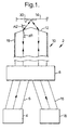
- Fig. 1 is an optical scheme of a small optical microphone/sensor having a splitter according to the present invention;
- Fig. 2 is an optical scheme of a small optical microphone/sensor having a partition, and
- Fig. 3 is an optical scheme of another embodiment of a small microphone/sensor with a partition.
-
- There is shown in Fig. 1 an optical scheme of a small optical microphone/sensor 2 according to the invention, comprising a light source 4, e.g., a LED, in optical contact with a light waveguide 6, e.g., an optical fiber or a solid waveguide. The light from light source 4 is transmitted to a splitter 8 and after it passes through the splitter, it proceeds along a light waveguide portion 10 to pointed face 12. Face 12 is inclined at an angle to the horizontal α1 and the light exits from face 12 at an angle α2, according to Snell's Law of Refraction
- Fig. 2 illustrates an optical scheme of another embodiment of a small optical microphone/sensor 2 without the use of a splitter, comprising a light source 4, e.g., an LED, a light detector 18 separated by an opaque partition 20 preventing direct optical communication between light source 4 and the light detector 18. The light source 4, light detector 18 and partition 20 are embedded at one end of a light waveguide 22 having a face 12 as described above with reference to Fig. 1. Light produced by light source 4 exists the face 12 at an angle α2 reflected by a surface 14, enters light waveguide 22 and is received by the detector 18 to be utilized as required. Light absorbing means 19 is also provided on the upper outer surface of waveguide 22.
- A third possible embodiment of a small microphone/sensor according to the present invention is shown in Fig. 3. Seen is a waveguide 28 having light-absorbing means 19, light source 4 separated from the light detector 18 by an opaque U-shaped partition 26. The light source 4, the light detector 18 and the partition 26 are set at one end of a light waveguide 28 having an opposite upper face 12.
- In all three embodiments of Figs. 1, 2 and 3, there is shown a small gold coating spot 30, made in the center of the reflected surface 14 for improved reflection of light under a wide range of temperatures.
- It will be evident to those skilled in the art that the invention is not limited to the details of the foregoing illustrated embodiments and that the present invention may be embodied in other specific forms without departing from the spirit or essential attributes thereof. The present embodiments are therefore to be considered in all respects as illustrative and not restrictive, the scope of the invention being indicated by the appended claims rather than by the foregoing description, and all changes which come within the meaning and range of equivalency of the claims are therefore intended to be embraced therein.
Claims (13)
- A small optical microphone/sensor for measuring distances to, and/or physical properties of, a reflective surface, comprising:a source of light coupled to a light waveguide for transmitting a light beam through said waveguide;said waveguide having at one of its ends a pointed face with an angle determined by Snell's Law of Refractionα1 is the angle of travel of said light beam through the waveguide media;α2 is the angle of travel of said light beam in a second media when exiting from said pointed face, andn1 and n2 are the light indices of said light waveguide media and said second media;said reflective surface being disposed at an optimal distance from said pointed face as determined by the angle α2;said waveguide having, at its outer surface, at least adjacent to said pointed face, means for preventing light waves impinging on said surface from being reflected back into said waveguide, anda light detector arranged to receive the light reflected from said surface.
- The optical microphone/sensor as claimed in claim 1, wherein said light waveguide has a first portion proximal to said pointed face and a second portion distal to said pointed face, said light source and said light detector being coupled to said second portion.
- The optical microphone/sensor as claimed in claim 2, wherein at least one of said light source and said light detector is embedded in said second portion.
- The optical microphone/sensor as claimed in claim 2, wherein said second portion is a split portion, said light source is coupled to one part of said split portion, and said light detector is coupled to another part of said split portion.
- The optical microphone/sensor as claimed in claim 4, wherein at least said second portion is constituted by optical fibers.
- The optical microphone/sensor as claimed in claim 4, further comprising a splitter coupled between said first and second portions.
- The optical microphone/sensor as claimed in claim 2, further comprising an opaque partition extending between said light source and said light detector.
- The optical microphone/sensor as claimed in claim 6, wherein said light source and said light detector are laterally displaced from each other.
- The optical microphone/sensor as claimed in claim 2, wherein said light source is centrally located in said second portion and said light detector is coupled below a partition separating the light source from the detector, so as to receive reflected light passing through said light waveguide around said partition.
- The optical microphone/sensor as claimed in claim 1, wherein said reflective surface is a membrane.
- The optical microphone/sensor as claimed in claim 10, wherein said membrane is provided, at least at its central surface, with a highly reflective coating.
- The optical microphone/sensor as claimed in claim 1, wherein said means for preventing light waves from being reflected is a light-absorbing material coated on the outer surface of said waveguide.
- The optical microphone/sensor as claimed in claim 1, wherein said means for preventing light waves from being reflected is obtained by machining the outer surface of said waveguide.
Applications Claiming Priority (2)
| Application Number | Priority Date | Filing Date | Title |
|---|---|---|---|
| IL13528100 | 2000-03-27 | ||
| IL13528100A IL135281A (en) | 2000-03-27 | 2000-03-27 | Small optical microphone/sensor |
Publications (1)
| Publication Number | Publication Date |
|---|---|
| EP1139072A1 true EP1139072A1 (en) | 2001-10-04 |
Family
ID=11073979
Family Applications (1)
| Application Number | Title | Priority Date | Filing Date |
|---|---|---|---|
| EP01302769A Withdrawn EP1139072A1 (en) | 2000-03-27 | 2001-03-26 | Small optical microphone/sensor |
Country Status (4)
| Country | Link |
|---|---|
| US (1) | US6462808B2 (en) |
| EP (1) | EP1139072A1 (en) |
| JP (1) | JP2003227749A (en) |
| IL (1) | IL135281A (en) |
Cited By (1)
| Publication number | Priority date | Publication date | Assignee | Title |
|---|---|---|---|---|
| WO2003049494A1 (en) * | 2001-12-07 | 2003-06-12 | Epivalley Co., Ltd. | Optical microphone |
Families Citing this family (14)
| Publication number | Priority date | Publication date | Assignee | Title |
|---|---|---|---|---|
| US7668322B2 (en) * | 2001-05-18 | 2010-02-23 | Tpo Hong Kong Holding Limited | Device for detecting pressure fluctuations, display device, recording device and sound reproduction system |
| US6937778B2 (en) * | 2003-03-25 | 2005-08-30 | Lockheed Martin Corporation | Sensor arrays having light-powered transducers |
| JP2004294214A (en) * | 2003-03-26 | 2004-10-21 | Nippon Soken Inc | Gas detecting device |
| US20060082838A1 (en) * | 2004-10-18 | 2006-04-20 | Ming-Der Chou | Carriage used in image scanning devices |
| WO2008064506A2 (en) * | 2006-11-27 | 2008-06-05 | Kistler Holding Ag | Optical pressure sensor having at least two optical fibers |
| FR3026838B1 (en) | 2014-10-01 | 2016-11-25 | Phonoptics | OPTO-MECHANICAL TRANSDUCER FOR VIBRATION DETECTION |
| US10609475B2 (en) | 2014-12-05 | 2020-03-31 | Stages Llc | Active noise control and customized audio system |
| US9654868B2 (en) | 2014-12-05 | 2017-05-16 | Stages Llc | Multi-channel multi-domain source identification and tracking |
| US9747367B2 (en) | 2014-12-05 | 2017-08-29 | Stages Llc | Communication system for establishing and providing preferred audio |
| US9508335B2 (en) | 2014-12-05 | 2016-11-29 | Stages Pcs, Llc | Active noise control and customized audio system |
| US9980042B1 (en) | 2016-11-18 | 2018-05-22 | Stages Llc | Beamformer direction of arrival and orientation analysis system |
| US10945080B2 (en) | 2016-11-18 | 2021-03-09 | Stages Llc | Audio analysis and processing system |
| US9980075B1 (en) | 2016-11-18 | 2018-05-22 | Stages Llc | Audio source spatialization relative to orientation sensor and output |
| CN111129201B (en) * | 2019-12-27 | 2021-07-02 | 武汉光谷信息光电子创新中心有限公司 | a photodetector |
Citations (8)
| Publication number | Priority date | Publication date | Assignee | Title |
|---|---|---|---|---|
| CH455304A (en) * | 1963-09-09 | 1968-06-28 | Mechanical Tech Inc | Device for measuring small distances |
| JPS5838903A (en) * | 1981-09-01 | 1983-03-07 | Matsushita Electric Ind Co Ltd | Optical coupler |
| EP0263016A1 (en) * | 1986-09-22 | 1988-04-06 | SEXTANT Avionique | Displacement and proximity detector with three optical fibres |
| US4758065A (en) * | 1985-03-08 | 1988-07-19 | Mechanical Technology Incorporated | Fiber optic sensor probe |
| EP0274772A2 (en) * | 1984-01-20 | 1988-07-20 | Hughes Aircraft Company | Fiber optic structure |
| US5031987A (en) * | 1990-01-02 | 1991-07-16 | Sundstrand Data Control, Inc. | Fiber optic thermal switch utilizing frustrated total internal reflection readout |
| FR2739445A1 (en) * | 1995-10-03 | 1997-04-04 | Alliance Tech Ind | Fibre optic reflectometry device for physical measurement |
| WO1999049302A1 (en) * | 1998-03-20 | 1999-09-30 | Aventis Research & Technologies Gmbh & Co. Kg | Optical sensor |
Family Cites Families (4)
| Publication number | Priority date | Publication date | Assignee | Title |
|---|---|---|---|---|
| US5089697A (en) * | 1989-01-11 | 1992-02-18 | Prohaska Otto J | Fiber optic sensing device including pressure detection and human implantable construction |
| IL111913A (en) * | 1994-12-07 | 1997-07-13 | Phone Or Ltd | Sensor and a method for measuring distances to, and/or physical properties of, a medium |
| US5969838A (en) * | 1995-12-05 | 1999-10-19 | Phone Or Ltd. | System for attenuation of noise |
| IL126172A (en) * | 1998-09-10 | 2002-05-23 | Phone Or Ltd | Sensor and method for measuring distances to, and/or physical properties of, a medium |
-
2000
- 2000-03-27 IL IL13528100A patent/IL135281A/en not_active IP Right Cessation
-
2001
- 2001-03-26 EP EP01302769A patent/EP1139072A1/en not_active Withdrawn
- 2001-03-27 US US09/823,963 patent/US6462808B2/en not_active Expired - Fee Related
- 2001-03-27 JP JP2001091260A patent/JP2003227749A/en active Pending
Patent Citations (8)
| Publication number | Priority date | Publication date | Assignee | Title |
|---|---|---|---|---|
| CH455304A (en) * | 1963-09-09 | 1968-06-28 | Mechanical Tech Inc | Device for measuring small distances |
| JPS5838903A (en) * | 1981-09-01 | 1983-03-07 | Matsushita Electric Ind Co Ltd | Optical coupler |
| EP0274772A2 (en) * | 1984-01-20 | 1988-07-20 | Hughes Aircraft Company | Fiber optic structure |
| US4758065A (en) * | 1985-03-08 | 1988-07-19 | Mechanical Technology Incorporated | Fiber optic sensor probe |
| EP0263016A1 (en) * | 1986-09-22 | 1988-04-06 | SEXTANT Avionique | Displacement and proximity detector with three optical fibres |
| US5031987A (en) * | 1990-01-02 | 1991-07-16 | Sundstrand Data Control, Inc. | Fiber optic thermal switch utilizing frustrated total internal reflection readout |
| FR2739445A1 (en) * | 1995-10-03 | 1997-04-04 | Alliance Tech Ind | Fibre optic reflectometry device for physical measurement |
| WO1999049302A1 (en) * | 1998-03-20 | 1999-09-30 | Aventis Research & Technologies Gmbh & Co. Kg | Optical sensor |
Non-Patent Citations (1)
| Title |
|---|
| PATENT ABSTRACTS OF JAPAN vol. 7, no. 121 (P - 199)<1266> 25 May 1983 (1983-05-25) * |
Cited By (1)
| Publication number | Priority date | Publication date | Assignee | Title |
|---|---|---|---|---|
| WO2003049494A1 (en) * | 2001-12-07 | 2003-06-12 | Epivalley Co., Ltd. | Optical microphone |
Also Published As
| Publication number | Publication date |
|---|---|
| US6462808B2 (en) | 2002-10-08 |
| JP2003227749A (en) | 2003-08-15 |
| IL135281A0 (en) | 2001-05-20 |
| IL135281A (en) | 2004-05-12 |
| US20020012115A1 (en) | 2002-01-31 |
Similar Documents
| Publication | Publication Date | Title |
|---|---|---|
| US6462808B2 (en) | Small optical microphone/sensor | |
| US5633748A (en) | Fiber optic Bragg grating demodulator and sensor incorporating same | |
| US4235113A (en) | Optical fiber acoustical sensors | |
| US6694031B2 (en) | Optical microphone/sensors | |
| JP5345547B2 (en) | Optical pressure sensor having at least two optical fibers | |
| US4310905A (en) | Acoustical modulator for fiber optic transmission | |
| CA1267790A (en) | Fiber optic doppler anemometer | |
| CN109945965A (en) | Support beam arm type sensitive diaphragm for fiber optic EFPI ultrasonic sensor | |
| EP0985911A2 (en) | A sensor and a method for measuring distance to, and/or physical properties of, a medium | |
| US20020075474A1 (en) | Sub miniaturized laser doppler velocimeter sensor | |
| US6618124B2 (en) | Optical microphone/sensor | |
| US20020171822A1 (en) | Thin optical microphone/sensor | |
| JPH09257696A (en) | Surface plasmon resonance sensor | |
| CN111787439A (en) | Retro-reflection based highly fault-tolerant fiber optic microphone | |
| US6519392B2 (en) | Optical tap collimator using an uncoated GRIN lens | |
| CN208383151U (en) | A kind of integral type micro-displacement optical fiber sensing probe | |
| WO2001096821A3 (en) | Microchip laser vibration sensor | |
| CN116839639A (en) | Optical fiber sensor and detection device | |
| KR20050077455A (en) | Optical antenna and wireless optical system using the same | |
| JP2002044773A (en) | Acoustic lens and ultrasonic transmitter | |
| GB1584048A (en) | Optical transducers | |
| JP2006508368A (en) | Optical hydrophone for measuring sound pressure distribution in liquid media | |
| JPH11316155A (en) | Optical sensor and optical microphone | |
| JP7405469B2 (en) | System and method for side illumination of waveguides | |
| ATE298417T1 (en) | SENSOR SYSTEM |
Legal Events
| Date | Code | Title | Description |
|---|---|---|---|
| PUAI | Public reference made under article 153(3) epc to a published international application that has entered the european phase |
Free format text: ORIGINAL CODE: 0009012 |
|
| AK | Designated contracting states |
Kind code of ref document: A1 Designated state(s): AT BE CH CY DE DK ES FI FR GB GR IE IT LI LU MC NL PT SE TR |
|
| AX | Request for extension of the european patent |
Free format text: AL;LT;LV;MK;RO;SI |
|
| 17P | Request for examination filed |
Effective date: 20020315 |
|
| AKX | Designation fees paid |
Free format text: AT BE CH CY DE DK ES FI FR GB GR IE IT LI LU MC NL PT SE TR |
|
| STAA | Information on the status of an ep patent application or granted ep patent |
Free format text: STATUS: THE APPLICATION HAS BEEN WITHDRAWN |
|
| 18W | Application withdrawn |
Withdrawal date: 20020621 |