EP1139045A2 - Refrigerator appliance with cool water dispensing unit - Google Patents
Refrigerator appliance with cool water dispensing unit Download PDFInfo
- Publication number
- EP1139045A2 EP1139045A2 EP01201010A EP01201010A EP1139045A2 EP 1139045 A2 EP1139045 A2 EP 1139045A2 EP 01201010 A EP01201010 A EP 01201010A EP 01201010 A EP01201010 A EP 01201010A EP 1139045 A2 EP1139045 A2 EP 1139045A2
- Authority
- EP
- European Patent Office
- Prior art keywords
- solenoid valve
- water
- refrigerator appliance
- tank
- orifice
- Prior art date
- Legal status (The legal status is an assumption and is not a legal conclusion. Google has not performed a legal analysis and makes no representation as to the accuracy of the status listed.)
- Granted
Links
Images



Classifications
-
- B—PERFORMING OPERATIONS; TRANSPORTING
- B67—OPENING, CLOSING OR CLEANING BOTTLES, JARS OR SIMILAR CONTAINERS; LIQUID HANDLING
- B67D—DISPENSING, DELIVERING OR TRANSFERRING LIQUIDS, NOT OTHERWISE PROVIDED FOR
- B67D1/00—Apparatus or devices for dispensing beverages on draught
- B67D1/0003—Apparatus or devices for dispensing beverages on draught the beverage being a single liquid
- B67D1/0009—Apparatus or devices for dispensing beverages on draught the beverage being a single liquid the beverage being stored in an intermediate container connected to a supply
-
- F—MECHANICAL ENGINEERING; LIGHTING; HEATING; WEAPONS; BLASTING
- F25—REFRIGERATION OR COOLING; COMBINED HEATING AND REFRIGERATION SYSTEMS; HEAT PUMP SYSTEMS; MANUFACTURE OR STORAGE OF ICE; LIQUEFACTION SOLIDIFICATION OF GASES
- F25D—REFRIGERATORS; COLD ROOMS; ICE-BOXES; COOLING OR FREEZING APPARATUS NOT OTHERWISE PROVIDED FOR
- F25D23/00—General constructional features
- F25D23/12—Arrangements of compartments additional to cooling compartments; Combinations of refrigerators with other equipment, e.g. stove
- F25D23/126—Water cooler
-
- B—PERFORMING OPERATIONS; TRANSPORTING
- B67—OPENING, CLOSING OR CLEANING BOTTLES, JARS OR SIMILAR CONTAINERS; LIQUID HANDLING
- B67D—DISPENSING, DELIVERING OR TRANSFERRING LIQUIDS, NOT OTHERWISE PROVIDED FOR
- B67D2210/00—Indexing scheme relating to aspects and details of apparatus or devices for dispensing beverages on draught or for controlling flow of liquids under gravity from storage containers for dispensing purposes
- B67D2210/00028—Constructional details
- B67D2210/00031—Housing
- B67D2210/00034—Modules
- B67D2210/00036—Modules for use with or in refrigerators
Definitions
- the present invention refers to a refrigerator appliance with unit for dispensing cool water.
- Household refrigerators are known that, within them, are provided with drink dispensing devices. Such devices are suitable to contain, inside of the heat insulated case of the refrigerator, a bottle containing the desired drink, in upside down position, and they comprise a tap, for instance a pressure type one, that opens when one wants to fill a glass with the drink. In this way, the drink in the bottle is kept at the temperature present inside the heat insulated case of the refrigerator.
- Some refrigerators are provided with devices for dispensing water coming from an external water network.
- a circuit for the connection to an external water network and a hydraulic circuit internal to the refrigerator which is suitable to take the water up to a tank internal to the heat insulated case of the refrigerator are provided; a tap connected with the aforesaid tank provides for dispensing water on the outside.
- the tank usually made of plastic material, can break if the pressure of the water increases and this happens due both to the cooling of the drinking water as well as due to the increase in the pressure of the water coming from the external water network.
- scope of the present invention is to provide a refrigerator appliance with cool water dispensing unit that allows to solve the aforesaid inconvenience.
- a refrigerator appliance comprising a heat insulated case and a unit for dispensing water coming from an external water network
- said unit comprising a first direct operation solenoid valve connected with said external water network, a tank located inside said heat insulated case and which receives water coming from the external water network through said first solenoid valve, a second direct operation solenoid valve located downstream of said tank, a water dispenser external to the refrigerator appliance, said first solenoid valve having an orifice for the flow of water inside the tank and said second solenoid valve having an orifice for the flow of water toward the dispenser, characterized in that said orifice of said first solenoid valve has a section smaller than the orifice of said second solenoid valve in order to reduce the pressure inside the water circuit comprised between said two solenoid valves.
- the positioning of the filtering device assigned to the elimination of chlorine and other organic compounds from the drinking water downstream of the tank allows that only a small amount of water is constantly non chlorinated and therefore not disinfected.
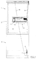
- the refrigerator comprises in a way known per se a cabinet 1 that encloses on its inside a heat insulated case 2 and, on the bottom of the same, a freezing cell 3.
- the heat insulated case 2 and the freezing cell 3 are frontally open and they are provided with doors 4 and 5 that are hinged to the cabinet 1 so as to be revolving around a vertical axis.
- On the back of the case 2 a condenser and a compressor are provided that are part of a known refrigeration system not visible in the figures.
- the refrigerator is provided with a water inlet 7, that is connectable with the household water network.
- a solenoid valve 8 is associated with the water inlet 7.
- a water transport duct 9 housed in a back interspace of the cabinet 1, goes up to the top of cabinet 1, continues into a upper interspace of the cabinet 1 toward the front part of the same, passes through the door 4 and end up in a water accumulation tank 10 that is destined to contain a reserve of drinking water.
- the tank 10 is mounted onto the internal wall of the door 4 as a bracket and it preferably has an elongated shape.
- a filtering device 11 is associated that is suitable to carry out a chemical filtering function of the water supplied by the water network, for the elimination of possible organic compounds, of products of the reaction of the chlorine contained in the water, of substances reliesed by the pipes of the water network, better visible in Figure 3.
- a dispensing device 12 is connected comprising a tap 13 that takes the filtered water on the outside.
- a second solenoid valve 14 is located between the filtering device 11 and the dispensing device 12 .
- the dispensing device 12 comprises a tap 13 consisting of a right angle tubular the duct 15 and it is provided with a button 16 adjacent to one end 30 of the tap which is connected with the valve means 14 and control to the opening or the closing of the same tap.
- the dispensing device 12 also comprises a frame 17, made up of a sheet of plastic material, applied onto the outside of the door 4 of the heat insulated case 3 in a substantially central position.
- the frame 17 comprises a recessed part 18 provided with a substantially rectangular hole 19 on top and an upper projection 20.
- the latter is suitable to contain the external portion of the tap 13 in such a way that the end 30 of the same tap can project from the hole 19 together with the button 16.
- the recessed part 18 of the frame 17 is made in such a way so as to allow to fill with water not only a glass but even other types of larger containers such as bottles.
- the solenoid valve 8 is activated at every pressure on the button 19. In this way the inflow of water from the water network external to the tank 10 is allowed through the duct 9 and the quantity of water that flows into the tank is equal to the amount of water that is drawn by the user with the tank 10 always kept full.
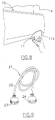
- connection of the inlet 7 with the external water network is carried out by means of a coupling device 21, shown in Figure 9, that is made up of a hose 22 and two threaded ring nuts 23, 24 provided with appropriate internal packings.
- the ring nuts 23, 24 are respectively connectable with the threaded inlet 7 of the solenoid valve 8 and with a tap existing in the building where the refrigerator is located. If too long the hose 22 can be shortened by uncoupling it from its connection with a ring nut, by cutting it and by subsequently coupling it with the ring nut.
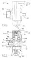
- the solenoid valve 8 is of the direct operation type and it is provided with a liter counter 70 for the count of the amount of water that flows inside it.
- the solenoid valve 8 comprises a body 80 that is made up of the threaded hole 7 for the connection with the external water network in such a way that the water passes through a hole 81 with a diameter that is decreasing while getting toward the inside of solenoid valve 8 and preferably provided with a mesh 82 for the filtering of the water.
- the hole 81 leads inside a chamber 83 that has a cylindrical shape but transversally cut by an oblique wall 84.
- the chamber 83 has a cylindrical body 85 inside of it that together with the wall 84 delimits the chamber 83 on the bottom.
- the cylindrical body 85 is hollow and it has on its top 86 a round orifice 87, preferably 1.6mm in diameter, for the flow of water through its inside; the orifice 87 is normally closed by a piston 88 that is thrust by a spring 89 located in a tubular duct 90 of a piece 95 for the closing of the chamber 83.
- the tubular duct 90 is in turn located inside a body 91 containing a coil that allows the lifting of the piston 88 according to a known operation and therefore the flow of the water inside the cylindrical body 85. The latter takes the water to the liter counter 30 that provides to count the amount of water that is brought through the outlet 92 inside of the tube 9.
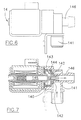
- the second solenoid valve 14, controlled by the button 19 too, is a directed operation solenoid valve, better shown in Figures 6 and 7, which is similar to the solenoid valve 8 but has a round orifice 140, for the flow of water larger than the orifice 88 found in the solenoid valve 8, it preferably has a diameter of 2mm.
- Such solenoid valve 14 allows the water of the dispensing unit not to come to contact with the external air.
- a duct 141 for the inlet of the filtered water is provided that through the holes 142 that are made in a packing 144 flows into an area 143. If the piston 145 does not close the orifice 140 the filtered water can flow inside a tube 146 that leads it toward the tap 13.
- a non-return valve for the water to avoid the flow of water from the dispensing unit toward the water network is located upstream of the solenoid valve 8 or it is inserted into it.
- the operation of the dispensing unit is as following.
- the water coming from the water network passes through the supply hose 22 and the inlet 7 of the solenoid valve 8 and through the hole 81 it is lead inside the chamber 83.
- the tank 10 After having flowed inside the tube 9 the water reaches the tank 10 located on the internal wall of the door 4 of heat insulated case 2.
- the tank 10 is generally made up of plastic material, it has an elongated U-shape and it is provided with two threaded inlets 101, 102 obtained by moulding during the same moulding of the tank 10.
- the water reaches the filtering device 11 made up of a body 110 to which a filter 111 is connected on the bottom that is arranged inside a container 112 screwable to the body 110 and which has a glass-like shape. Finally the water goes through the solenoid valve 14 and it reaches the device 12 for its output on the outside.
- the same button When one operates on the button 19 so as to stop the output of water the same button simultaneously controls the closing of the solenoid valve 8 by means of the lowering of the piston 88 on the orifice 87 and of the solenoid valve 14 by closing the orifice 140 by means of the piston 145.
- the difference in dimension between the two orifices 87 and 140 determines a delayed closing of the orifice 140 and this causes a reduction in the pressure of the water inside the output circuit that is called residual pressure. This allows to prevent possible breaks of the tank 10 and possible high pressure water jets from the tap 13.
- the aim is to guarantee a water pressure inside the dispenser unit that is comprised between 0.2 and 2 bars with a network pressure comprised between 0.2 bars and 8 bars, considering the fact that the cooling of the drinking water inside the tank causes the pressure of the water to raise, for instance the passage from 10 degrees to 4 degrees determines an increase in the pressure of the water inside of tank 10 equal to 1atm.
- the solenoid valve 8 is preferably calibrated at 8 bars in order to be able to resist possible sudden changes in pressure (the so-called the "water hammer") of the water in the external water network.
- the solenoid valve 14 is preferably calibrated at 4 bars. In this way such solenoid valve 14 signals the breakdown of the solenoid valve 8 by closing itself; in fact a breakdown of the solenoid valve 8 determines an increase in pressure inside the circuit of the dispensing unit that cause the closing of the solenoid valve 14 thus stopping in such way the output of water. If that happens the user can contact the service department for the control of the dispenser system of the refrigerator appliance.
- an air bag 200 made of a chamber 201 containing air and insulated by a membrane 202 from the part of the tank 10 that contains water, is inserted inside the tank 10 in order to additionally lower the residual pressure inside the dispensing unit, as shown in Figure 10.
- the presence of two solenoid valves 8 and 14 facilitates the operation of substitution of the filter 111 that can take place also in the presence of water in the water circuit between two solenoid valves 8, 14.
- Such operation is carried out every time the liter counter counts an amount of water equal to 1000 liters; that is signaled by the ignition of an appropriate LED that can preferably be already flashing when the count reaches 950 litres.
- Such operation provides for the unscrewing of the glass 110 that contains the filter 111, the uncoupling of the same and its substitution, and the subsequent screwing back of the glass, as shown in Figure 8.
Landscapes
- Engineering & Computer Science (AREA)
- Chemical & Material Sciences (AREA)
- Combustion & Propulsion (AREA)
- Physics & Mathematics (AREA)
- Mechanical Engineering (AREA)
- Thermal Sciences (AREA)
- General Engineering & Computer Science (AREA)
- Devices That Are Associated With Refrigeration Equipment (AREA)
Abstract
Description
Claims (11)
- Refrigerator appliance comprising a heat insulated case (2) and a unit for dispensing water coming from an external water network, said unit comprising a first direct operation solenoid valve (8) connected with said external water network, a tank (10) located inside said heat insulated case (2) and which receives water coming from the external water network through said first solenoid valve (8), a second direct operation solenoid valve (14) located downstream of said tank (10), a water dispenser (13) external to the refrigerator appliance, said first solenoid valve (8) having an orifice (87) for the flow of water inside the tank (10) and said second solenoid valve (14) having an orifice (140) for the flow of the water toward the dispenser (13), characterized in that said orifice (87) of said first solenoid valve (8) has a section smaller than the orifice (140) of said second solenoid valve (14) in order to reduce the pressure inside the water circuit comprised between said two solenoid valves (8, 14).
- Refrigerator appliance according to claim 1, characterized in that the orifice (87) of said first solenoid valve (8) is circular and it is substantially 1.6 millimetres in diameter and the orifice (140) of said second solenoid valve (14) is circular and it is substantially 2 millimetres in diameter.
- Refrigerator appliance according to claim 1, characterized in that said second solenoid valve (14) is calibrated in pressure in minor way as compared with said first solenoid valve (8) in such a way that its closing signals a breakdown of the first solenoid valve (8).
- Refrigerator appliance according to claim 3, characterized in that said first solenoid valve (8) is calibrated at 8 bars and said second solenoid valve (14) is calibrated at 4 bars.
- Refrigerator appliance according to claim 1, characterized in that said first solenoid valve (8) is provided with a liter counter (70) for the count of the amount of water that flows through it.
- Refrigerator appliance according to claim 1, characterized in that said dispensing unit comprises a filtering device (11) located between said tank (10) and said second solenoid valve (14).
- Refrigerator appliance according to claim 6, characterized in that said filtering device (11) comprises a filter (111) and a container shaped as a glass (112) that is easy removable for the substitution of the filter (111).
- Refrigerator appliance according to claim 7 and 5, characterized in that it provides for the substitution of said filter (111) of the filtering device (11) to the attainment of a pre-established amount of water that flows through said first solenoid valve (8).
- Refrigerator appliance according to claim 6, characterized in that said heat insulated case (2) is open and it is closed by a door (4) and said tank (10) and said filtering device (11) are arranged on the internal wall of said door (4) of said heat insulated case (2).
- Refrigerator appliance according to claim 1, characterized in that there are provided means (21) for the connection of said first solenoid valve (8) to the external water network, said connection means (21) comprising a flexible and shortenable hose (22).
- Refrigerator appliance according to claim 1, characterized in that said tank (10) comprises an air bag (200) in order to additionally reduce the pressure inside said water circuit between the two solenoid valves (8, 14).
Applications Claiming Priority (2)
| Application Number | Priority Date | Filing Date | Title |
|---|---|---|---|
| IT2000MI000675A IT1316866B1 (en) | 2000-03-31 | 2000-03-31 | REFRIGERATOR APPARATUS WITH AQUARINFRESCATA DISPENSING APPARATUS. |
| ITMI000675 | 2000-03-31 |
Publications (3)
| Publication Number | Publication Date |
|---|---|
| EP1139045A2 true EP1139045A2 (en) | 2001-10-04 |
| EP1139045A3 EP1139045A3 (en) | 2002-02-13 |
| EP1139045B1 EP1139045B1 (en) | 2004-10-06 |
Family
ID=11444686
Family Applications (1)
| Application Number | Title | Priority Date | Filing Date |
|---|---|---|---|
| EP01201010A Expired - Lifetime EP1139045B1 (en) | 2000-03-31 | 2001-03-19 | Refrigerator appliance with cool water dispensing unit |
Country Status (3)
| Country | Link |
|---|---|
| EP (1) | EP1139045B1 (en) |
| ES (1) | ES2228742T3 (en) |
| IT (1) | IT1316866B1 (en) |
Cited By (15)
| Publication number | Priority date | Publication date | Assignee | Title |
|---|---|---|---|---|
| KR20050051971A (en) * | 2003-11-28 | 2005-06-02 | 엘지전자 주식회사 | Water tank for refrigerator |
| WO2005045335A3 (en) * | 2003-10-28 | 2005-08-11 | Cuno Inc | Improved designs for filtration systems within appliances |
| EP1624266A1 (en) * | 2004-08-03 | 2006-02-08 | Indesit Company S.p.A. | Refrigerating apparatus with water distributor |
| KR100705196B1 (en) | 2004-06-16 | 2007-04-06 | 엘지전자 주식회사 | Water supply pipe of the dispenser for refrigerator |
| KR100705197B1 (en) | 2004-06-16 | 2007-04-06 | 엘지전자 주식회사 | Water supply pipe of the dispenser for refrigerator |
| US7210601B2 (en) | 2004-06-04 | 2007-05-01 | Whirlpool Corporation | Variable flow water dispenser for refrigerator freezers |
| WO2007062915A1 (en) * | 2005-11-30 | 2007-06-07 | BSH Bosch und Siemens Hausgeräte GmbH | Refrigeration device and water filter for said device |
| US7261815B2 (en) | 2005-10-12 | 2007-08-28 | Whirlpool Corporation | Water filter for refrigerator water dispenser |
| KR100764310B1 (en) | 2004-06-16 | 2007-10-05 | 엘지전자 주식회사 | Dispenser water supply pipe for French door type refrigerator |
| KR100780833B1 (en) | 2004-06-08 | 2007-11-29 | 엘지전자 주식회사 | Water Tank Installation Structure of Dispenser for Refrigerator |
| WO2007082739A3 (en) * | 2006-01-18 | 2007-11-29 | Re Flex Srl | Liquid tank for a refrigerator |
| WO2008025379A1 (en) * | 2006-08-29 | 2008-03-06 | BSH Bosch und Siemens Hausgeräte GmbH | Refrigerator with a water tank |
| WO2008035201A2 (en) | 2006-09-21 | 2008-03-27 | BSH Bosch und Siemens Hausgeräte GmbH | Improvements to a water dispensing device mounted in refrigerator doors |
| EP3273193A1 (en) * | 2016-07-19 | 2018-01-24 | BSH Hausgeräte GmbH | Water-guiding component assembly for a household cooling appliance |
| DE10392722B4 (en) | 2002-05-31 | 2019-05-02 | Lg Electronics Inc. | fridge |
Families Citing this family (2)
| Publication number | Priority date | Publication date | Assignee | Title |
|---|---|---|---|---|
| KR101327460B1 (en) * | 2006-08-11 | 2013-11-08 | 엘지전자 주식회사 | Refrigerator |
| DE102024200462A1 (en) * | 2024-01-18 | 2025-07-24 | BSH Hausgeräte GmbH | Household refrigeration appliance with an ice and/or water dispenser with specific water pressure setting, and method |
Family Cites Families (5)
| Publication number | Priority date | Publication date | Assignee | Title |
|---|---|---|---|---|
| US3358471A (en) * | 1966-08-15 | 1967-12-19 | Butcher Troy | Refrigerating system |
| US3429140A (en) * | 1968-02-09 | 1969-02-25 | Gen Electric | Household refrigerator including ice and water dispensing means |
| US4918426A (en) * | 1988-05-02 | 1990-04-17 | Amway Corporation | Method and apparatus for sensing fluid flow volume to indicate end of filter life |
| US5003790A (en) * | 1989-08-16 | 1991-04-02 | Robert Goupil | Adaptor to convert a bottle fed water cooler into a device supplied with pressurized water from the local piping system |
| US5813245A (en) * | 1996-10-25 | 1998-09-29 | White Consolidated Industries, Inc. | Pressure relief circuit for refrigerator contained water filter |
-
2000
- 2000-03-31 IT IT2000MI000675A patent/IT1316866B1/en active
-
2001
- 2001-03-19 EP EP01201010A patent/EP1139045B1/en not_active Expired - Lifetime
- 2001-03-19 ES ES01201010T patent/ES2228742T3/en not_active Expired - Lifetime
Cited By (19)
| Publication number | Priority date | Publication date | Assignee | Title |
|---|---|---|---|---|
| DE10392722B4 (en) | 2002-05-31 | 2019-05-02 | Lg Electronics Inc. | fridge |
| WO2005045335A3 (en) * | 2003-10-28 | 2005-08-11 | Cuno Inc | Improved designs for filtration systems within appliances |
| KR20050051971A (en) * | 2003-11-28 | 2005-06-02 | 엘지전자 주식회사 | Water tank for refrigerator |
| US7210601B2 (en) | 2004-06-04 | 2007-05-01 | Whirlpool Corporation | Variable flow water dispenser for refrigerator freezers |
| KR100780833B1 (en) | 2004-06-08 | 2007-11-29 | 엘지전자 주식회사 | Water Tank Installation Structure of Dispenser for Refrigerator |
| KR100764310B1 (en) | 2004-06-16 | 2007-10-05 | 엘지전자 주식회사 | Dispenser water supply pipe for French door type refrigerator |
| KR100705196B1 (en) | 2004-06-16 | 2007-04-06 | 엘지전자 주식회사 | Water supply pipe of the dispenser for refrigerator |
| KR100705197B1 (en) | 2004-06-16 | 2007-04-06 | 엘지전자 주식회사 | Water supply pipe of the dispenser for refrigerator |
| EP1624266A1 (en) * | 2004-08-03 | 2006-02-08 | Indesit Company S.p.A. | Refrigerating apparatus with water distributor |
| US8496823B2 (en) | 2005-10-12 | 2013-07-30 | Whirlpool Corporation | Water filter for refrigerator water dispenser |
| US7261815B2 (en) | 2005-10-12 | 2007-08-28 | Whirlpool Corporation | Water filter for refrigerator water dispenser |
| US8354024B2 (en) | 2005-11-30 | 2013-01-15 | Bsh Bosch Und Siemens Hausgeraete Gmbh | Refrigeration device and water filter for said device |
| WO2007062915A1 (en) * | 2005-11-30 | 2007-06-07 | BSH Bosch und Siemens Hausgeräte GmbH | Refrigeration device and water filter for said device |
| WO2007082739A3 (en) * | 2006-01-18 | 2007-11-29 | Re Flex Srl | Liquid tank for a refrigerator |
| WO2008025379A1 (en) * | 2006-08-29 | 2008-03-06 | BSH Bosch und Siemens Hausgeräte GmbH | Refrigerator with a water tank |
| CN101523140B (en) * | 2006-08-29 | 2012-04-18 | Bsh博世和西门子家用器具有限公司 | Refrigeration unit with water tank |
| WO2008035201A2 (en) | 2006-09-21 | 2008-03-27 | BSH Bosch und Siemens Hausgeräte GmbH | Improvements to a water dispensing device mounted in refrigerator doors |
| EP3273193A1 (en) * | 2016-07-19 | 2018-01-24 | BSH Hausgeräte GmbH | Water-guiding component assembly for a household cooling appliance |
| US10591193B2 (en) | 2016-07-19 | 2020-03-17 | Bsh Hausgeraete Gmbh | Water-guiding component assembly for a household cooling appliance |
Also Published As
| Publication number | Publication date |
|---|---|
| EP1139045A3 (en) | 2002-02-13 |
| ITMI20000675A0 (en) | 2000-03-31 |
| ITMI20000675A1 (en) | 2001-10-01 |
| IT1316866B1 (en) | 2003-05-12 |
| ES2228742T3 (en) | 2005-04-16 |
| EP1139045B1 (en) | 2004-10-06 |
Similar Documents
| Publication | Publication Date | Title |
|---|---|---|
| EP1139045B1 (en) | Refrigerator appliance with cool water dispensing unit | |
| EP1572573B1 (en) | Tap adapter having a conduit with a flow restrictor | |
| CN113924267A (en) | Water distribution station | |
| JP4563576B2 (en) | Assembly for storing and discharging beer and other carbonated beverages | |
| US7815079B2 (en) | Rapid comestible fluid dispensing apparatus and method | |
| US4830223A (en) | Drinking water sending and dispensing system | |
| CA2069351A1 (en) | Syrup dosing valve for use in installations for the preparation of carbonated flavored beverages | |
| KR20060126779A (en) | Liquid dispenser assembly for use with the application device | |
| EP0695278B1 (en) | Bottled water station with removable reservoir and manifolded support platform | |
| EP3123909B1 (en) | Water valve and water dispenser | |
| EP2751019A2 (en) | An apparatus for dispensing a liquid from a liquid storage container | |
| KR101597184B1 (en) | Apparatus for suppling Water | |
| GB2160847A (en) | Tapping device for postmixed drinks | |
| WO2001032550A1 (en) | Apparatus for dispensing a beverage | |
| JP2007537951A (en) | Tap adapter for barrels with flow restriction | |
| KR101167405B1 (en) | Sealed Type Check Valve Dispenser System With Sterlization | |
| US5395014A (en) | Bottled water station with sweat-free dispenser faucet | |
| CA2324198A1 (en) | Ice transport system | |
| EP1139044B1 (en) | Refrigerator appliance with drink dispensing device | |
| CN111071975A (en) | Multi-class sterile beverage machine | |
| JP2590065Y2 (en) | Dispensing structure of beverage dispensing device | |
| RU94560U1 (en) | MECHANISM OF FASTENING OF THE NECK OF THE TANK TO THE DRAINAGE CHANNEL OF THE DEVICE FOR MANUAL FILLING OF FOAMING DRINKS AND THE DEVICE FOR MANUAL FILLING OF FOAMING FOAM BEVERAGES WITH ITS USE | |
| KR20000008543U (en) | Bottled water bottle upright cold water heater | |
| JPH0685299U (en) | Connection structure of concentrated stock solution container in beverage dispenser | |
| RU2327630C2 (en) | Device for beer pouring |
Legal Events
| Date | Code | Title | Description |
|---|---|---|---|
| PUAI | Public reference made under article 153(3) epc to a published international application that has entered the european phase |
Free format text: ORIGINAL CODE: 0009012 |
|
| AK | Designated contracting states |
Kind code of ref document: A2 Designated state(s): ES FR GB IT Kind code of ref document: A2 Designated state(s): AT BE CH CY DE DK ES FI FR GB GR IE IT LI LU MC NL PT SE TR |
|
| AX | Request for extension of the european patent |
Free format text: AL;LT;LV;MK;RO;SI |
|
| PUAL | Search report despatched |
Free format text: ORIGINAL CODE: 0009013 |
|
| AK | Designated contracting states |
Kind code of ref document: A3 Designated state(s): AT BE CH CY DE DK ES FI FR GB GR IE IT LI LU MC NL PT SE TR |
|
| AX | Request for extension of the european patent |
Free format text: AL;LT;LV;MK;RO;SI |
|
| 17P | Request for examination filed |
Effective date: 20020730 |
|
| AKX | Designation fees paid |
Free format text: ES FR GB IT |
|
| REG | Reference to a national code |
Ref country code: DE Ref legal event code: 8566 |
|
| GRAP | Despatch of communication of intention to grant a patent |
Free format text: ORIGINAL CODE: EPIDOSNIGR1 |
|
| GRAS | Grant fee paid |
Free format text: ORIGINAL CODE: EPIDOSNIGR3 |
|
| GRAA | (expected) grant |
Free format text: ORIGINAL CODE: 0009210 |
|
| AK | Designated contracting states |
Kind code of ref document: B1 Designated state(s): ES FR GB IT |
|
| REG | Reference to a national code |
Ref country code: GB Ref legal event code: FG4D |
|
| REG | Reference to a national code |
Ref country code: IE Ref legal event code: FG4D |
|
| REG | Reference to a national code |
Ref country code: ES Ref legal event code: FG2A Ref document number: 2228742 Country of ref document: ES Kind code of ref document: T3 |
|
| PLBE | No opposition filed within time limit |
Free format text: ORIGINAL CODE: 0009261 |
|
| STAA | Information on the status of an ep patent application or granted ep patent |
Free format text: STATUS: NO OPPOSITION FILED WITHIN TIME LIMIT |
|
| ET | Fr: translation filed | ||
| 26N | No opposition filed |
Effective date: 20050707 |
|
| PGFP | Annual fee paid to national office [announced via postgrant information from national office to epo] |
Ref country code: IT Payment date: 20120319 Year of fee payment: 12 |
|
| PGFP | Annual fee paid to national office [announced via postgrant information from national office to epo] |
Ref country code: ES Payment date: 20130308 Year of fee payment: 13 Ref country code: GB Payment date: 20130321 Year of fee payment: 13 |
|
| PGFP | Annual fee paid to national office [announced via postgrant information from national office to epo] |
Ref country code: FR Payment date: 20130425 Year of fee payment: 13 |
|
| GBPC | Gb: european patent ceased through non-payment of renewal fee |
Effective date: 20140319 |
|
| REG | Reference to a national code |
Ref country code: FR Ref legal event code: ST Effective date: 20141128 |
|
| PG25 | Lapsed in a contracting state [announced via postgrant information from national office to epo] |
Ref country code: GB Free format text: LAPSE BECAUSE OF NON-PAYMENT OF DUE FEES Effective date: 20140319 Ref country code: FR Free format text: LAPSE BECAUSE OF NON-PAYMENT OF DUE FEES Effective date: 20140331 |
|
| PG25 | Lapsed in a contracting state [announced via postgrant information from national office to epo] |
Ref country code: IT Free format text: LAPSE BECAUSE OF NON-PAYMENT OF DUE FEES Effective date: 20140319 |
|
| REG | Reference to a national code |
Ref country code: ES Ref legal event code: FD2A Effective date: 20150730 |
|
| PG25 | Lapsed in a contracting state [announced via postgrant information from national office to epo] |
Ref country code: ES Free format text: LAPSE BECAUSE OF NON-PAYMENT OF DUE FEES Effective date: 20140320 |