EP1138907B1 - Fuel injection system - Google Patents
Fuel injection systemInfo
- Publication number
- EP1138907B1 EP1138907B1 EP00106973A EP00106973A EP1138907B1 EP 1138907 B1 EP1138907 B1 EP 1138907B1 EP 00106973 A EP00106973 A EP 00106973A EP 00106973 A EP00106973 A EP 00106973A EP 1138907 B1 EP1138907 B1 EP 1138907B1
- Authority
- EP
- European Patent Office
- Prior art keywords
- voltage
- piezoelectric element
- piezoelectric elements
- charging
- discharging
- Prior art date
- Legal status (The legal status is an assumption and is not a legal conclusion. Google has not performed a legal analysis and makes no representation as to the accuracy of the status listed.)
- Expired - Lifetime
Links
- 239000000446 fuel Substances 0.000 title claims description 66
- 238000002347 injection Methods 0.000 title claims description 56
- 239000007924 injection Substances 0.000 title claims description 56
- 238000007599 discharging Methods 0.000 claims description 78
- 238000000034 method Methods 0.000 claims description 41
- 230000004913 activation Effects 0.000 description 34
- 230000006870 function Effects 0.000 description 12
- 230000002950 deficient Effects 0.000 description 10
- 239000003990 capacitor Substances 0.000 description 9
- 238000005259 measurement Methods 0.000 description 6
- 238000002485 combustion reaction Methods 0.000 description 5
- 230000007423 decrease Effects 0.000 description 5
- 238000006073 displacement reaction Methods 0.000 description 4
- 101100129500 Caenorhabditis elegans max-2 gene Proteins 0.000 description 3
- 238000010586 diagram Methods 0.000 description 3
- 230000003993 interaction Effects 0.000 description 3
- 230000008569 process Effects 0.000 description 3
- 239000000470 constituent Substances 0.000 description 2
- 230000008602 contraction Effects 0.000 description 2
- 230000007547 defect Effects 0.000 description 2
- 230000003071 parasitic effect Effects 0.000 description 2
- 238000013459 approach Methods 0.000 description 1
- 230000005540 biological transmission Effects 0.000 description 1
- 230000015556 catabolic process Effects 0.000 description 1
- 230000001419 dependent effect Effects 0.000 description 1
- 238000003745 diagnosis Methods 0.000 description 1
- 230000000694 effects Effects 0.000 description 1
- 239000012530 fluid Substances 0.000 description 1
- 238000011545 laboratory measurement Methods 0.000 description 1
- 239000000203 mixture Substances 0.000 description 1
- 230000004044 response Effects 0.000 description 1
- 238000000926 separation method Methods 0.000 description 1
Images


Classifications
-
- F—MECHANICAL ENGINEERING; LIGHTING; HEATING; WEAPONS; BLASTING
- F02—COMBUSTION ENGINES; HOT-GAS OR COMBUSTION-PRODUCT ENGINE PLANTS
- F02D—CONTROLLING COMBUSTION ENGINES
- F02D41/00—Electrical control of supply of combustible mixture or its constituents
- F02D41/20—Output circuits, e.g. for controlling currents in command coils
- F02D41/2096—Output circuits, e.g. for controlling currents in command coils for controlling piezoelectric injectors
-
- H—ELECTRICITY
- H02—GENERATION; CONVERSION OR DISTRIBUTION OF ELECTRIC POWER
- H02N—ELECTRIC MACHINES NOT OTHERWISE PROVIDED FOR
- H02N2/00—Electric machines in general using piezoelectric effect, electrostriction or magnetostriction
- H02N2/02—Electric machines in general using piezoelectric effect, electrostriction or magnetostriction producing linear motion, e.g. actuators; Linear positioners ; Linear motors
- H02N2/06—Drive circuits; Control arrangements or methods
- H02N2/065—Large signal circuits, e.g. final stages
- H02N2/067—Large signal circuits, e.g. final stages generating drive pulses
-
- H—ELECTRICITY
- H10—SEMICONDUCTOR DEVICES; ELECTRIC SOLID-STATE DEVICES NOT OTHERWISE PROVIDED FOR
- H10N—ELECTRIC SOLID-STATE DEVICES NOT OTHERWISE PROVIDED FOR
- H10N30/00—Piezoelectric or electrostrictive devices
- H10N30/80—Constructional details
- H10N30/802—Drive or control circuitry or methods for piezoelectric or electrostrictive devices not otherwise provided for
Landscapes
- Engineering & Computer Science (AREA)
- Chemical & Material Sciences (AREA)
- Combustion & Propulsion (AREA)
- Mechanical Engineering (AREA)
- General Engineering & Computer Science (AREA)
- Fuel-Injection Apparatus (AREA)
- Electrical Control Of Air Or Fuel Supplied To Internal-Combustion Engine (AREA)
- Combined Controls Of Internal Combustion Engines (AREA)
Description
- The present invention relates to a fuel injection system as defined in the preamble of
claim 1, and a method as defined in the preamble ofclaim 10. - A fuel injection system and a method as defined in the aforementioned preambles are known from DE 198 41 002 C1 or US 5,376,854.
- The fuel injection system comprises piezoelectric elements being considered in more detail. Piezoelectric elements can be used as actuators because, as is known, they possess the property of contracting or expanding as a function of a voltage applied thereto or occurring therein.
- The practical implementation of actuators using piezoelectric elements proves to be advantageous in particular if the actuator in question must perform rapid and/or frequent movements.
- The use of piezoelectric elements as actuators proves to be advantageous, inter alia, in fuel injection nozzles for internal combustion engines. Reference is made, for example, to
EP 0 371 469 B1 and toEP 0 379 182 B1 regarding the usability of piezoelectric elements in fuel injection nozzles. - Piezoelectric elements are capacitive elements which, as already partially alluded to above, contract and expand in accordance with the particular charge state or the voltage occurring therein or applied thereto. In the example of a fuel injection nozzle, expansion and contraction of piezoelectric elements is used to control valves that manipulate the linear strokes of injection needles. The use of piezoelectric elements with double acting, double seat valves to control corresponding injection needles in a fuel injection system is system is shown in German patent applications DE 197 42 073 A1 and DE 197 29 844 A1.
- Fuel injection systems using piezoelectric elements are characterized by the fact that, to a first approximation, piezoelectric elements exhibit a proportional relationship between applied voltage and the linear expansion. In a fuel injection nozzle, for example, implemented as a double acting, double seat valve to control the linear stroke of a needle for fuel injection into a cylinder of an internal combustion engine, the amount of fuel injected into a corresponding cylinder is a function of the time the valve is open, and in the case of the use of a piezoelectric element, the activation voltage applied to the piezoelectric element.
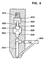
- Fig. 8 is a schematic representation of a fuel injection system using a
piezoelectric element 2010 as an actuator. Referring to Fig. 8, thepiezoelectric element 2010 is electrically energized to expand and contract in response to a given activation voltage. Thepiezoelectric element 2010 is coupled to apiston 2015. In the expanded state, thepiezoelectric element 2010 causes thepiston 2015 to protrude into ahydraulic adapter 2020 which contains a hydraulic fluid, for example fuel. As a result of the piezoelectric element's expansion, a doubleacting control valve 2025 is hydraulically pushed away fromhydraulic adapter 2020 and thevalve plug 2035 is extended away from a first closedposition 2040. The combination of doubleacting control valve 2025 andhollow bore 2050 is often referred to as double acting, double seat valve for the reason that whenpiezoelectric element 2010 is in an unexcited state, the doubleacting control valve 2025 rests in its first closedposition 2040. On the other hand, when thepiezoelectric element 2010 is fully extended, it rests in its second closedposition 2030. The later position ofvalve plug 2035 is schematically represented with ghost lines in Fig. 8. - The fuel injection system comprises an
injection needle 2070 allowing for injection of fuel from a pressurizedfuel supply line 2060 into the cylinder (not shown). When thepiezoelectric element 2010 is unexcited or when it is fully extended, the doubleacting control valve 2025 rests respectively in its first closedposition 2040 or in its second closedposition 2030. In either case, the hydraulic rail pressure maintainsinjection needle 2070 at a closed position. Thus, the fuel mixture does not enter into the cylinder (not shown). Conversely, when thepiezoelectric element 2010 is excited such that doubleacting control valve 2025 is in the so-called mid-position with respect to thehollow bore 2050, then there is a pressure drop in the pressurizedfuel supply line 2060. This pressure drop results in a pressure differential in the pressurizedfuel supply line 2060 between the top and the bottom of theinjection needle 2070 so that theinjection needle 2070 is lifted allowing for fuel injection into the cylinder (not shown). - It is an object of the present invention to identify defective piezoelectric elements.
- This object is achieved, according to the present invention, by way of the features claimed in
claim 1 and claimed inclaim 10. - An inventive fuel injection system with a piezoelectric element for controlling the amount of injected fuel, comprises a control unit for determination of a possible fault of the piezoelectric element or of an electric circuitry driving the piezoelectric element based upon a value related to the capacitance of the piezoelectric element. This provides for a very effective diagnosis of the piezoelectric element and/or the circuitry driving the piezoelectric element. The circuitry driving the piezoelectric element may comprise switches for selection of particular piezoelectric elements or the power stage. The present invention is preferably used for detecting faults, in particular shortcuts in switches for selecting particular piezoelectric elements. Especially if there is a defective cylinder selecting switch the corresponding piezoelectric element would charge every time in parallel to another piezoelectric element so that a cylinder, corresponding to that defective cylinder selecting switch is filled with such a large amount of fuel that serious damage to the engine could occur. If there is a shortcut in the connection between power stage and the piezoelectric element similar serious problems might occur.
- According to the invention the fuel injection system comprises at least two piezoelectric elements for controlling the amount of injected fuel, wherein the control unit is able to determine a possible fault of at least one of the piezoelectric elements or the electric circuitry driving the piezoelectric elements based upon a quotient of values related to two capacitances of the two piezoelectric elements.
- In a further preferred embodiment of the invention the piezoelectric element is charged from a first voltage to a second voltage, wherein the control unit determines the value related to the capacitance of the piezoelectric element based upon the first voltage and the second voltage.
- In a further preferred embodiment of the invention the piezoelectric element is charged from a first voltage to a second voltage with in a charging time, wherein the control unit determines the value related to the capacitance of the piezoelectric element based upon the charging time, and, in particular an estimated value of, a current charging the piezoelectric element. In a further embodiment of the invention the value related to the capacitance of the piezoelectric element is the difference between the first voltage and the second voltage or a function of that difference if charging time and charging current are kept essentially constant (with respect to the time instances the values related to the capacitance is calculated for or with respect to different piezoelectric elements). In a further embodiment of the invention the value related to the capacitance of the piezoelectric element is the charging time or a function of the charging time, if the difference between the first voltage and the second voltage and the current charging the piezoelectric element are kept essentially constant (with respect to the time instances the values related to the capacitance is calculated for or with respect to different piezoelectric elements). In a further embodiment of the invention the value related to the capacitance of the piezoelectric element is the current charging the piezoelectric element or a function of the current if the difference between the first voltage and the second voltage and the charging time are kept essentially constant (with respect to the time instances the values related to the capacitance is calculated for or with respect to different piezoelectric elements).
- In a further preferred embodiment of the invention the control unit determines the value related to the capacitance of the piezoelectric element based upon the charge the piezoelectric element is carrying. In a possible embodiment of the invention the value related to the capacitance of the piezoelectric element is the charge the piezoelectric element is carrying or a function of this charge if the (first, second, third) voltage is kept essentially constant (with respect to the time instances the values related to the capacitance is calculated for or with respect to different piezoelectric elements).
- In a further preferred embodiment of the invention the control unit determines the value related to the capacitance of the piezoelectric element based upon the quotient of the second voltage and the charge the piezoelectric element is carrying, based upon the quotient of the charge the piezoelectric element is carrying and the second voltage, based upon the quotient of the difference between the second voltage and the first voltage and the product of the charging time and the current charging the piezoelectric element, or based upon the quotient of the product of the charging time and the current charging the piezoelectric element and the difference between the second voltage and the first voltage. If one of the quantities charging time, current charging the piezoelectric element or difference between second voltage and the first voltage is kept essentially constant (with respect to the time instances the values related to the capacitance is calculated for or with respect to different piezoelectric elements), it can be replaced by one or another constant value.
- In a further preferred embodiment of the invention the piezoelectric element is discharged from a second voltage to a third voltage, wherein the control unit determines the value related to the capacitance of the piezoelectric element based upon the second voltage and the third voltage.
- In a further preferred embodiment of the invention the piezoelectric element is discharged from a second voltage to a third voltage within a discharging time, wherein within a discharging time the control unit determines the value related to the capacitance of the piezoelectric element based upon the discharging time, and, in particular an estimated value of, a current discharging the piezoelectric element. In a further embodiment of the invention the value related to the capacitance of the piezoelectric element is the difference between the third voltage and the second voltage or a function of that difference if charging time and charging current are kept essentially constant (with respect to the time instances the values related to the capacitance is calculated for or with respect to different piezoelectric elements) . In a further embodiment of the invention the value related to the capacitance of the piezoelectric element is the discharging time or a function of the discharging time, if the difference between the third voltage and the second voltage and the current discharging the piezoelectric element are kept essentially constant (with respect to the time instances the values related to the capacitance is calculated for or with respect to different piezoelectric elements). In a further embodiment of the invention the value related to the capacitance of the piezoelectric element is the current discharging the piezoelectric element or a function of the current if the difference between the third voltage and the second voltage and the discharging time are kept essentially constant (with respect to the time instances the values related to the capacitance is calculated for or with respect to different piezoelectric elements).
- In a further preferred embodiment of the invention the control unit determines the value related to the capacitance of the piezoelectric element based upon the quotient of the third voltage and the charge the piezoelectric element is carrying, based upon the quotient of the charge the piezoelectric element is carrying and the third voltage, based upon the quotient of the difference between the second voltage and the third voltage and the product of the discharging time and the current discharging the piezoelectric element, or based upon the quotient of the product of the discharging time and the current discharging the piezoelectric element and the difference between the second voltage and the third voltage. If one of the quantities charging time, current charging the piezoelectric element or difference between second voltage and the first voltage is kept essentially constant (with respect to the time instances the values related to the capacitance is calculated for or with respect to different piezoelectric elements), it can be replaced by one or another constant value.
- In a further embodiment of the invention the third voltage equals the first voltage.
- In a further preferred embodiment of the invention the control unit is able to determine a possible fault of the piezoelectric element or electric circuitry driving the piezoelectric element based upon a calculated value of the capacitance of the piezoelectric element and a value related to the capacitance of the piezoelectric element at a former stage, in particular based upon a comparison of the value related to the capacitance of the piezoelectric element and a former value related to the capacitance of the piezoelectric element.
- In a further preferred embodiment of the invention the fuel injection system according to one of the foregoing claims wherein the fuel injection system comprises a switch (11, 21, 31, 41, 51 or 61) for discharging the piezoelectric element, wherein the control unit is able to determine a possible short cut of the switch (11, 21,31, 41, 51 or 61) based upon the value related to the capacitance of the piezoelectric element.
- The invention will be explained below in more detail with reference to exemplary embodiments, referring to the figures in which:
- Fig. 1
- shows a graph depicting the relationship between activation voltage and injected fuel volume in a fixed time period for the example of a double acting control valve;
- Fig. 2
- shows a schematic profile of an exemplary control valve stroke and a corresponding nozzle needle lift for the example of a double acting control valve;
- Fig. 3
- shows a block diagram of an exemplary embodiment of an arrangement in which the present invention may be implemented;
- Fig. 4A
- shows a depiction to explain the conditions occurring during a first charging phase (
charging switch 220 closed) in the circuit of Fig. 3; - Fig. 4B
- shows a depiction to explain the conditions occurring during a second charging phase (charging
switch 220 open again) in the circuit of Fig. 3; - Fig. 4C
- shows a depiction to explain the conditions occurring during a first discharging phase (discharging
switch 230 closed) in the circuit of Fig. 3; - Fig. 4D
- shows a depiction to explain the conditions occurring during a second discharging phase (discharging
switch 230 open again) in the circuit of Fig. 3; - Fig. 5
- shows a block diagram of components of the activation IC E which is also shown in Fig. 3;
- Fig. 6
- shows a flow chart according to an embodiment of the present invention for detecting out of tolerance piezoelectric actuators.
- Fig. 7
- shows a flow chart according to an embodiment of the present invention in particular for detecting defects of the power stage or of a cable supplying the voltage for driving a piezoelectric element of a fuel injector; and
- Fig. 8
- shows a schematic representation of a fuel injection system using a piezoelectric element as an actuator.
- Fig. 1 shows a graph depicting the relationship between activation voltage U and injected fuel volume mE during a preselected fixed time period, for an exemplary fuel injection system using piezoelectric elements acting upon double seat control valves. The y-axis represents volume mE of fuel injected into a cylinder chamber during the preselected fixed period of time. The x-axis represents the activation voltage U applied to or stored in the corresponding piezoelectric element, used to displace a valve plug of the double seat control valve.
- At x=0, y=0, the activation voltage U is zero, and the valve plug is seated in a first closed position to prevent the flow of fuel during the preselected fixed period of time. For values of the activation voltage U greater than zero, up to the x-axis point indicated as Uopt, the represented values of the activation voltage U cause the displacement of the valve plug away from the first seat and towards the second seat, in a manner that results in a greater volume mE of injected fuel for the fixed time period, as the activation voltage U approaches Uopt, up to the value for volume indicted on the y-axis by mE,max. The point mE,max, corresponding to the greatest volume for the injected fuel during the fixed period of time, represents the value of the activation voltage for application to or charging of the piezoelectric element, that results in an optimal displacement of the valve plug between the first and second valve seats.
- As shown on the graph of Fig. 1, for values of the activation voltage U greater than Uopt, the volume mE of fuel injected during the fixed period of time decrease until it reaches zero. This represents displacement of the valve plug from the optimal point and toward the second seat of the double seat valve until the valve plug is seated against the second valve seat. Thus, the graph of Fig. 1 illustrates that a maximum volume of fuel injection occurs when the activation voltage causes the piezoelectric element to displace the valve plug to the optimal point.
- Fig. 2 shows a double graph representing a schematic profile of an exemplary control valve stroke, to illustrate the double seat valve operation discussed above. In the upper graph of Fig. 2, the x-axis represents time, and the y-axis represents displacement of the valve plug (valve lift). In the lower graph of Fig. 2, the x-axis once again represents time, while the y-axis represents a nozzle needle lift to provide fuel flow, resulting from the valve lift of the upper graph. The upper and lower graphs are aligned with one another to coincide in time, as represented by the respective x-axises.
- During an injection cycle, the piezoelectric element is charged resulting in an expansion of the piezoelectric element, as will be described in greater detail, and causing the corresponding valve plug to move from the first seat to the second seat for a pre-injection stroke, as shown in the upper graph of Fig. 2. The lower graph of Fig. 2 shows a small injection of fuel that occurs as the valve plug moves between the two seats of the double seat valve, opening and closing the valve as the plug moves between the seats. In general, the charging of the piezoelectric element can be done in two steps: the first one is to charge it to a certain voltage and cause the valve to open and the second one is to charge it further and cause the valve to close again at the second seat. Between these steps, in general, there can be a certain time delay.
- After a preselected period of time, a discharging operation is then performed, as will be explained in greater detail below, to reduce the charge within the piezoelectric element so that it contracts, as will also be described in greater detail, causing the valve plug to move away from the second seat, and hold at a midway point between the two seats. As indicated in Fig. 1, the activation voltage within the piezoelectric element is to reach a value that equals Uopt to correspond to an optimal point of the valve lift, and thereby obtain a maximum fuel flow, mE,max, during the period of time allocated to a main injection. The upper and lower graphs of Fig. 2 show the holding of the valve lift at a midway point, resulting in a main fuel injection.
- At the end of the period of time for the main injection, the piezoelectric element is discharged to an activation voltage of zero, resulting in further contraction of the piezoelectric element, to cause the valve plug to move away from the optimal position, towards the first seat, closing the valve and stopping fuel flow, as shown in the upper and lower graphs of Fig. 2. At this time, the valve plug will once again be in a position to repeat another pre-injection, main injection cycle, as just described above, for example. Of course, any other injection cycle can be performed.
- Fig. 3 provides a block diagram of an exemplary embodiment of an arrangement in which the present invention may be implemented.
- In Fig. 3 there is a detailed area A and a non-detailed area B, the separation of which is indicated by a dashed line c. The detailed area A comprises a circuit for charging and discharging
piezoelectric elements piezoelectric elements piezoelectric elements - The non-detailed area B comprises a control unit D and a activation IC E by both of which the elements within the detailed area A are controlled, as well as a measuring system F for measuring system operating characteristics such as, for example, fuel pressure and rotational speed (rpm) of the internal combustion engine for input to and use by the control unit D, according to the present invention, as will be described in detail below. According to the present invention, the control unit D and activation IC E are programmed to control activation voltages for piezoelectric elements as a function of operating characteristics of the each particular piezoelectric element.
- The following description firstly introduces the individual elements within the detailed area A. Then, the procedures of charging and discharging
piezoelectric elements - The circuit within the detailed area A comprises six
piezoelectric elements - The
piezoelectric elements piezoelectric elements piezoelectric elements - The group selector switches 310, 320 are arranged between a
coil 240 and the respective groups G1 and G2 (the coil-side terminals thereof) and are implemented as transistors.Side drivers -
Diodes 315 and 325 (referred to as group selector diodes), respectively, are provided in parallel with the group selector switches 310, 320. If the group selector switches 310, 320 are implemented as MOSFETs, thesegroup selector diodes diodes piezoelectric elements - Within each group G1 resp. G2 the
piezoelectric elements piezoelectric branches piezoelectric element resistor transistor diode - The branch resistors 13, 23, 33, 43, 53 resp. 63 cause each corresponding
piezoelectric element piezoelectric element branch resistors piezoelectric element branch resistors piezoelectric elements branch resistors - The branch selector switch/branch diode pairs in the individual
piezoelectric branches diode 12 inpiezoelectric branch 110,selector switch 21 anddiode 22 inpiezoelectric branch 120, and so on, can be implemented using electronic switches (i.e. transistors) with parasitic diodes, for example MOSFETs or IGBTs (as stated above for the group selector switch/diode pairs 310 and 315 resp. 320 and 325). - The branch selector switches 11, 21, 31, 41, 51 resp. 61 can be used to establish which of the
piezoelectric elements piezoelectric elements - The
branch diodes piezoelectric elements - Returning to the
piezoelectric elements piezoelectric terminals diodes resistor 300. - The purpose of
resistor 300 is to measure the currents that flow during charging and discharging of thepiezoelectric elements piezoelectric terminals piezoelectric elements opening charging switch 220 and dischargingswitch 230 in a manner dependent on the magnitude of the currents, it is possible to set the charging current and discharging current to predefined average values and/or to keep them from exceeding or falling below predefined maximum and/or minimum values as is explained in further detail below. - In the example considered, the measurement itself further requires a
voltage source 621 which supplies a voltage of 5 V DC, for example, and a voltage divider implemented as tworesistors point 620 and which cannot be handled by means of activation IC E: such negative voltages are changed into positive voltages by means of addition with a positive voltage setup which is supplied byvoltage source 621 andvoltage divider resistors - The other terminal of each
piezoelectric element piezoelectric terminal group selector switch 310 resp. 320 or via thegroup selector diode 315 resp. 325 as well as via acoil 240 and a parallel circuit made up of a chargingswitch 220 and a chargingdiode 221, and alternatively or additionally connected to ground via thegroup selector switch 310 resp. 320 or viadiode 315 resp. 325 as well as via thecoil 240 and a parallel circuit made up of a dischargingswitch 230 or a dischargingdiode 231. Chargingswitch 220 and dischargingswitch 230 are implemented as transistors, for example, which are controlled viaside drivers 222 resp. 232. - The voltage source comprises an element having capacitive properties which, in the example being considered, is the (buffer)
capacitor 210.Capacitor 210 is charged by a battery 200 (for example a motor vehicle battery) and aDC voltage converter 201 downstream therefrom.DC voltage converter 201 converts the battery voltage (for example, 12 V) into substantially any other DC voltage (for example 250 V), and charges capacitor 210 to that voltage.DC voltage converter 201 is controlled by means oftransistor switch 202 andresistor 203 which is utilized for current measurements taken from ameasuring point 630. - For cross check purposes, a further current measurement at a
measuring point 650 is allowed by activation IC E as well as byresistors source 654; moreover, a voltage measurement at ameasuring point 640 is allowed by activation IC E as well as byvoltage dividing resistors - Finally, a resistor 330 (referred to as total discharging resistor), a stop switch implemented as a transistor 331 (referred to as stop switch), and a diode 332 (referred to as total discharging diode) serve to discharge the
piezoelectric elements Stop switch 331 is preferably closed after "normal" discharging procedures (cycled discharging via discharge switch 230). It thereby connectspiezoelectric elements resistors piezoelectric elements total discharging diode 332 prevents negative voltages from occurring at thepiezoelectric elements - Charging and discharging of all the
piezoelectric elements battery 200,DC voltage converter 201,capacitor 210, chargingswitch 220 and dischargingswitch 230, chargingdiode 221 and dischargingdiode 231 andcoil 240. - The charging and discharging of each piezoelectric element works the same way and is explained in the following while referring to the first
piezoelectric element 10 only. - The conditions occurring during the charging and discharging procedures are explained with reference to Figs. 4A through 4D, of which Figs. 4A and 4B illustrate the charging of
piezoelectric element 10, and Figs. 4C and 4D the discharging ofpiezoelectric element 10. - The selection of one or more particular
piezoelectric elements - Concerning the charging procedure, firstly any particular
piezoelectric element piezoelectric element 10, the branch selector switch 11 of thefirst branch 110 is closed, whereas all other branch selector switches 21, 31, 41, 51 and 61 remain opened. In order to exclusively charge any otherpiezoelectric element - Then, the charging procedure itself may take place:
- Generally, within the example considered, the charging procedure requires a positive potential difference between
capacitor 210 and the group selectorpiezoelectric terminal 14 of the firstpiezoelectric element 10. However, as long as chargingswitch 220 and dischargingswitch 230 are open no charging or discharging ofpiezoelectric element 10 occurs: In this state, the circuit shown in Fig. 3 is in a steady-state condition, i.e. piezoelectricelement 10 retains its charge state in substantially unchanged fashion, and no currents flow. - In order to charge the first
piezoelectric element 10, chargingswitch 220 is closed. Theoretically, the firstpiezoelectric element 10 could become charged just by doing so. However, this would produce large currents which might damage the elements involved. Therefore, the occurring currents are measured at measuringpoint 620 and switch 220 is opened again as soon as the detected currents exceed a certain limit. Hence, in order to achieve any desired charge on the firstpiezoelectric element 10, chargingswitch 220 is repeatedly closed and opened whereas dischargingswitch 230 remains open. - In more detail, when charging
switch 220 is closed, the conditions shown in Fig. 4A occur, i.e. a closed circuit comprising a series circuit made up ofpiezoelectric element 10,capacitor 210, andcoil 240 is formed, in which a current iLE(t) flows as indicated by arrows in Fig. 4A. As a result of this current flow both positive charges are brought to the group selectorpiezoelectric terminal 14 of the firstpiezoelectric element 10 and energy is stored incoil 240. - When charging
switch 220 opens shortly (for example, a few µs) after it has closed, the conditions shown in Fig. 4B occur: a closed circuit comprising a series circuit made up ofpiezoelectric element 10, chargingdiode 221, andcoil 240 is formed, in which a current iLA(t) flows as indicated by arrows in Fig. 4B. The result of this current flow is that energy stored incoil 240 flows intopiezoelectric element 10. Corresponding to the energy delivery to thepiezoelectric element 10, the voltage occurring in the latter, and its external dimensions, increase. Once energy transport has taken place fromcoil 240 topiezoelectric element 10, the steady-state condition of the circuit, as shown in Fig. 3 and already described, is once again attained. - At that time, or earlier, or later (depending on the desired time profile of the charging operation), charging
switch 220 is once again closed and opened again, so that the processes described above are repeated. As a result of the re-closing and re-opening of chargingswitch 220, the energy stored inpiezoelectric element 10 increases (the energy already stored in thepiezoelectric element 10 and the newly delivered energy are added together), and the voltage occurring at thepiezoelectric element 10, and its external dimensions, accordingly increase. - If the aforementioned closing and opening of charging
switch 220 are repeated numerous times, the voltage occurring at thepiezoelectric element 10, and the expansion of thepiezoelectric element 10, rise in steps. - Once charging
switch 220 has closed and opened a predefined number of times, and/or oncepiezoelectric element 10 has reached the desired charge state, charging of the piezoelectric element is terminated by leaving chargingswitch 220 open. - Concerning the discharging procedure, in the example considered, the
piezoelectric elements - Firstly, the group selector switch(es) 310 and/or 320 of the group or groups G1 and/or G2 the piezoelectric elements of which are to be discharged are closed (the branch selector switches 11, 21, 31, 41, 51, 61 do not affect the selection of
piezoelectric elements branch diodes piezoelectric element 10 as a part of the first group G1, the firstgroup selector switch 310 is closed. - When discharging
switch 230 is closed, the conditions shown in Fig. 4C occur: a closed circuit comprising a series circuit made up ofpiezoelectric element 10 andcoil 240 is formed, in which a current iEE(t) flows as indicated by arrows in Fig. 4C. The result of this current flow is that the energy (a portion thereof) stored in the piezoelectric element is transported intocoil 240. Corresponding to the energy transfer frompiezoelectric element 10 tocoil 240, the voltage occurring at thepiezoelectric element 10, and its external dimensions, decrease. - When discharging
switch 230 opens shortly (for example, a few µs) after it has closed, the conditions shown in Fig. 4D occur: a closed circuit comprising a series circuit made up ofpiezoelectric element 10,capacitor 210, dischargingdiode 231, andcoil 240 is formed, in which a current iEA(t) flows as indicated by arrows in Fig. 4D. The result of this current flow is that energy stored incoil 240 is fed back intocapacitor 210. Once energy transport has taken place fromcoil 240 tocapacitor 210, the steady-state condition of the circuit, as shown in Fig. 3 and already described, is once again attained. - At that time, or earlier, or later (depending on the desired time profile of the discharging operation), discharging
switch 230 is once again closed and opened again, so that the processes described above are repeated. As a result of the re-closing and re-opening of dischargingswitch 230, the energy stored inpiezoelectric element 10 decreases further, and the voltage occurring at the piezoelectric element, and its external dimensions, also accordingly decrease. - If the aforementioned closing and opening of discharging
switch 230 are repeated numerous times, the voltage occurring at thepiezoelectric element 10, and the expansion of thepiezoelectric element 10, decrease in steps. - Once discharging
switch 230 has closed and opened a predefined number of times, and/or once the piezoelectric element has reached the desired discharge state, discharging of thepiezoelectric element 10 is terminated by leaving dischargingswitch 230 open. - The interaction between activation IC E and control unit D on the one hand and the elements within the detailed area A on the other hand is performed by control signals sent from activation IC E to elements within the detailed area A via branch
selector control lines selector control lines switch control line 530, chargingswitch control line 540 and dischargingswitch control line 550 andcontrol line 560. On the other hand, there are sensor signals obtained on measuringpoints sensor lines - The control lines are used to apply or not to apply voltages to the transistor bases in order to select
piezoelectric elements piezoelectric elements piezoelectric elements point 620. The control unit D and the activation IC E are used to combine both kinds of signals in order to perform an interaction of both as will be described in detail now while referring to Figs. 3 and 5. - As is indicated in Fig. 3, the control unit D and the activation IC E are connected to each other by means of a
parallel bus 840 and additionally by means of aserial bus 850. Theparallel bus 840 is particularly used for fast transmission of control signals from control unit D to the activation IC E, whereas theserial bus 850 is used for slower data transfer. - In Fig. 5 some components are indicated, which the activation IC E comprises: a
logic circuit 800,RAM memory 810, digital toanalog converter system 820 andcomparator system 830. Furthermore, it is indicated that the fast parallel bus 840 (used for control signals) is connected to thelogic circuit 800 of the activation IC E, whereas the slowerserial bus 850 is connected to theRAM memory 810. Thelogic circuit 800 is connected to theRAM memory 810, to thecomparator system 830 and to thesignal lines RAM memory 810 is connected to thelogic circuit 800 as well as to the digital toanalog converter system 820. The digital toanalog converter system 820 is further connected to thecomparator system 830. Thecomparator system 830 is further connected to thesensor lines logic circuit 800. - The above listed components may be used in a charging procedure for example as follows:
- By means of the control unit D a particular
piezoelectric element RAM memory 810 via the slowerserial bus 850. The target voltage can be, for example, the value for Uopt used in a main injection, as described above with respect to Fig. 1. Later or simultaneously, a code corresponding to the particularpiezoelectric element RAM memory 810 is transmitted to thelogic circuit 800 via theparallel bus 840. Later on, a strobe signal is sent to thelogic circuit 800 via theparallel bus 840 which gives the start signal for the charging procedure. - The start signal firstly causes the
logic circuit 800 to pick up the digital value of the target voltage from theRAM memory 810 and to put it on the digital toanalog converter system 820 whereby at one analog exit of theconverters 820 the desired voltage occurs. Moreover, said analog exit (not shown) is connected to thecomparator system 830. In addition hereto, thelogic circuit 800 selects either measuring point 600 (for any of thepiezoelectric elements piezoelectric elements comparator system 830. Resulting thereof, the target voltage and the present voltage at the selectedpiezoelectric element comparator system 830. The results of the comparison, i.e. the differences between the target voltage and the present voltage, are transmitted to thelogic circuit 800. - Thereby, the
logic circuit 800 can stop the procedure as soon as the target voltage and the present voltage are equal to one another. - Secondly, the
logic circuit 800 applies a control signal to thebranch selector switch piezoelectric element logic circuit 800 applies a control signal to the chargingswitch 220 so that the switch becomes closed. Furthermore, thelogic circuit 800 starts (or continues) measuring any currents occurring on measuringpoint 620. Hereto, the measured currents are compared to any predefined maximum value by thecomparator system 830. As soon as the predefined maximum value is achieved by the detected currents, thelogic circuit 800 causes the chargingswitch 220 to open again. - Again, the remaining currents at measuring
point 620 are detected and compared to any predefined minimum value. As soon as said predefined minimum value is achieved, thelogic circuit 800 causes the chargingswitch 220 to close again and the procedure starts once again. - The closing and opening of the charging
switch 220 is repeated as long as the detected voltage at measuringpoint 600 or 610 is below the target voltage. As soon as the target voltage is achieved, the logic circuit stops the continuation of the procedure. - The discharging procedure takes place in a corresponding way: Now the selection of the
piezoelectric element switch 230 instead of the chargingswitch 220 is opened and closed and a predefined minimum target voltage is to be achieved. - The timing of the charging and discharging operations and the holding of voltage levels in the
piezoelectric elements - It is to be understood that the above given description of the way charging or discharging procedures take place are exemplary only. Hence, any other procedure which utilizes the above described circuits or other circuits might match any desired purpose and any corresponding procedure may be used in place of the above described example.
- It is extremely important that the actuator travel be set with the highest accuracy possible. In this respect, a temperature dependence by the actuator travel has a decisive effect on the function of the entire common-rail injector. Temperature dependence of the actuator travel can be compensated by knowing the temperature dependence of its capacitance. In this process, the capacitance of a piezoelectric element is measured in the control unit and the temperature is determined by way of the capacitance-temperature relationship. This relationship could be established from laboratory measurement. Then during operation, the information in the capacitance-temperature relationship could be accessed to identify the temperature corresponding to the measured capacitance of the piezoelectric element.
- Preferably the capacitances of all of the piezoelectric elements are measured and compared. If the value of the capacitance for one of the piezoelectric element deviates from the average value of all measured capacitances by more than a specific amount, that piezoelectric element can be identified as defective independent of temperature. An erroneous temperature compensation can thus be avoided when such a determination is made. In addition, if defective piezoelectric element is detected a warning signal for the driver can be provided.
- The capacitance Ci of each piezoelectric element is determined in specific time intervals (for example, i=1 to 4 for a four cylinder engine). The average capacitance Cavg can then be calculated from these values, and a capacitance differential value, Ci-Cavg can further be calculated. If the absolute capacitance differential value, |Ci-Cavg|, for a piezoelectric element exceeds a permissible capacitance limit CΔ, that piezoelectric element can be classified as defective and that piezoelectric element would not be taken into account for making temperature compensations. As noted above, if the capacitance limit value of CΔ is exceeded, then a warning signal may be transmitted to the vehicle operator. Preferably the piezoelectric element which is identified as being defective.
- Fig. 6 shows a flow chart according to one embodiment of the present invention for detecting out of tolerance piezoelectric elements. Referring to Fig. 6,
step 7010 represents the measurement of the capacitance Ci of all piezoelectric elements. In this step, the piezoelectric elements' capacitance is obtained. - The value for the individual piezoelectric elements is then averaged in
step 7020 obtaining an average capacitance Cavg. Step 7020 is followed by adecision block 7030, deciding whether Ci-Cavg| exceeds the permissible capacitance limit CΔ. If the permissible capacitance limit CΔ is exceeded the piezoelectric element is classified as inoperable or defective and according tostep 7040, an error message can be provided to notify the driver of such error.Step 7040 is an optional but preferred embodiment. If |Ci-Cavg| is within the desired range, the entire procedure can be repeated after a given interval instep 7050. - Fig. 7 shows a flow chart to a preferred embodiment of the present invention in particular for detecting defects of the power stage or of a cable supplying the voltage for driving a piezoelectric element of a fuel injector. The start of the
program 8001 is followed by an initialization ofstep 8002 where a counter i is set to 0:
- The
initialization step 8002 is followed bystep 8003 incrementing i by 1:
-
Step 8003 is followed bydecision block 8004 determining whether
wherein n is the number of cylinders. In this embodiment to every cylinder one fuel injector comprising one piezoelectric element is assigned too. - If i is greater than n the program is terminated, i.e. in this
case decision block 8004 is followed by theend 8012. If this condition is not fulfilleddecision block 8004 is followed by adecision block 8005 checking whether
wherein Ci is the capacitance of the piezoelectric element controlling fuel injection into the ith cylinder and Ci+1 is the capacitance of the piezoelectric element controlling fuel injection into the (i+1)th cylinder. fmin1 is a tolerance value. fmin1 is preferably a value between 0,8 and 1, preferably in the range of 0,9. If the condition
decision block 8005 is followed bydecision block 8008. If however the condition
decision block 8005 is followed bydecision block 8006. - With
decision block 8008 it is determined whether the conditions

- If either one of the conditions


decision block 8008 is followed bystep 8003. If however both conditions

decision block 8008 is followed bystep 8009.Step 8009 defines the piezoelectric element controlling the fuel injection into cylinder i as being defective. Preferably an alarm is created and/or a failure message is recorded in a log. Afterstep 8009 the program is terminated. -
Decision block 8006 determines whether the condition
- If this condition is met
decision block 8006 is followed bydecision block 8003. If however this condition is not met,decision block 8006 is followed bydecision block 8007. -
Decision block 8007 determines whether the conditions

- If one of the conditions


decision block 8007 is followed by astep 8011 defining that an undefined failure has occurred. Preferably an alarm is created and/or a failure message is recorded into a log. - If however both of the conditions


decision block 8007 is followed by astep 8010.Step 8010 defines the piezoelectric element controlling the fuel injection into cylinder i+1 as being defective. Preferably an alarm is created and/or a failure message is recorded in a log. Afterstep 8010 the program is terminated. - It should be noted that Fig. 6 and Fig. 7 represent only embodiments of the claimed invention, and other methods for finding an inoperable piezoelectric element by comparing the piezoelectric elements' capacitance with a predetermined set of values is contemplated as within the scope of the present invention. In Fig. 6 and Fig. 7 the capacitance of the piezoelectric element is used as one example of the value related to the capacitance of the piezoelectric element. The examples are also valid if the capacitance of the piezoelectric element is replaced by another example of the value related to the capacitance of the piezoelectric element mentioned above.
Claims (10)
- Fuel injection system comprising at least two piezoelectric elements (10, 20, 30, 40, 50 or 60) for controlling the amount of injected fuel, wherein the fuel injection system comprises a control unit (D) for determination of a possible fault of at least one of the two piezoelectric elements (10, 20, 30, 40, 50 or 60) or of an electric circuitry driving the piezoelectric elements (10, 20, 30, 40, 50 or 60)
characterized in that
the control unit (D) determines a possible fault of at least one of the two piezoelectric elements (10, 20, 30, 40, 50 or 60) or of the electric circuitry driving the piezoelectric elements (10, 20, 30, 40, 50 or 60) based upon a quotient of two values wherein the first value of the quotient relates to a capacitance (Ci) of one of the two piezoelectric elements (10, 20, 30, 40, 50 or 60) and the second value of the quotient relates to a capacitance (Ci+1) of the other one of the two piezoelectric elements (10, 20, 30, 40, 50 or 60). - Fuel injection system according to claim 1 wherein each one of the piezoelectric elements (10, 20, 30, 40, 50 or 60) is charged from a first voltage to a second voltage,
characterized in that
the control unit (D) determines the values related to the two capacitances of the two piezoelectric elements (10, 20, 30, 40, 50 or 60) based upon the first voltage and the second voltage. - Fuel injection system according to claim 1 or 2, wherein each one of the piezoelectric elements (10, 20, 30, 40, 50 or 60) is charged from a first voltage to a second voltage within a charging time,
characterized in that
the control unit (D) determines the values related to the two capacitances of the two piezoelectric elements (10, 20, 30, 40, 50 or 60) based upon the charging time, and, in particular an estimated value of a current charging the piezoelectric elements (10, 20, 30, 40, 50 or 60). - Fuel injection system according to claim 1, 2 or 3,
characterized in that
the control unit (D) determines the values related to the two capacitances of the two piezoelectric elements (10, 20, 30, 40, 50 or 60) based upon the charge the respective piezoelectric element (10, 20, 30, 40, 50, or 60) is carrying. - Fuel injection system according to claim 1, 2, 3 or 4,
characterized in that
the control unit. (D) determines the values related to the capacitances of the piezoelectric elements (10, 20, 30, 40, 50 or 60) based upon the quotient of the second voltage and the charge the respective piezoelectric element (10, 20, 30, 40, 50 or 60) is carrying, based upon the quotient of the charge the respective piezoelectric element (10, 20, 30, 40, 50 or 60) is carrying and the second voltage, based upon the quotient of the difference between the second voltage and the first voltage and the product of the charging time and the current charging the respective piezoelectric element (10, 20, 30, 40, 50 or 60), or based upon the quotient of the product of the charging time and the current charging the respective piezoelectric element (10, 20, 30, 40, 50 or 60) and the difference between the second voltage and the first voltage. - Fuel injection system according to one of the foregoing claims, wherein each one of the piezoelectric elements (10, 20, 30, 40, 50 or 60) is discharged from a second voltage to a third voltage,
characterized in that
the control unit (D) determines the values related to the two capacitances of the two piezoelectric elements (10, 20, 30, 40, 50 or 60) based upon the second voltage and the third voltage. - Fuel injection system according to one of the foregoing claims, wherein each one of the piezoelectric elements (10, 20, 30, 40, 50 or 60) is discharged from a second voltage to a third voltage within a discharging time,
characterized in that
the control unit (D) determines the values related to the two capacitances of the two piezoelectric elements (10,20, 30, 40, 50 or 60) based upon the discharging time, and, in particular an estimated value of, a current discharging the respective piezoelectric element (10, 20, 30, 40, 50 or 60). - Fuel injection system according to one of the foregoing claims,
characterized in that
the control unit (D) determines the values related to the two capacitances of the two piezoelectric elements (10, 20, 30, 40, 50 or 60) based upon the quotient of the third voltage and the charge the respective piezoelectric element (10, 20, 30, 40, 50 or 60) is carrying, based upon the quotient of the charge the respective piezoelectric element (10, 20, 30, 40, 50 or 60) is carrying and the third voltage, based upon the quotient of the difference between the second voltage and the third voltage and the product of the discharging time and the current discharging the respective piezoelectric element (10, 20, 30, 40, 50 or 60), or based upon the quotient of the product of the discharging time and the current discharging the respective piezoelectric element (10, 20, 30, 40, 50 or 60) and the difference between the second voltage and the third voltage. - Fuel injection system according to claim 6, 7 or 8,
characterized in that
the third voltage equals the first voltage. - Method for operating a fuel injection system comprising at least two piezoelectric elements (10, 20, 30, 40, 50 or 60) for controlling the amount of injected fuel, wherein the fuel injection system comprises a control unit (D) for determination of a possible fault of at least one of the two piezoelectric elements (10, 20, 30, 40, 50 or 60) or of an electric circuitry driving the piezoelectric elements (10, 20, 30, 40, 50 or 60)
characterized in that
the control unit (D) determines a possible fault of at least one of the.two piezoelectric elements (10, 20, 30, 40, 50 or 60) or of the electric circuitry driving the piezoelectric elements (10, 20, 30, 40, 50 or 60) based upon a quotient of two values, wherein the first value of the quotient relates to a capacitance (Ci) of one of the two piezoelectric elements (10, 20, 30, 40, 50 or 60) and the second value of the quotient relates to a capacitance (Ci+1) of the other one of the two piezoelectric elements (10, 20, 30, 40, 50 or 60).
Priority Applications (4)
| Application Number | Priority Date | Filing Date | Title |
|---|---|---|---|
| DE60031092T DE60031092D1 (en) | 2000-04-01 | 2000-04-01 | Fuel injection system |
| EP00106973A EP1138907B1 (en) | 2000-04-01 | 2000-04-01 | Fuel injection system |
| JP2001103838A JP4669147B2 (en) | 2000-04-01 | 2001-04-02 | Fuel injection device and method of operating fuel injection device |
| US09/824,195 US6705291B2 (en) | 2000-04-01 | 2001-04-02 | Fuel injection system |
Applications Claiming Priority (1)
| Application Number | Priority Date | Filing Date | Title |
|---|---|---|---|
| EP00106973A EP1138907B1 (en) | 2000-04-01 | 2000-04-01 | Fuel injection system |
Publications (2)
| Publication Number | Publication Date |
|---|---|
| EP1138907A1 EP1138907A1 (en) | 2001-10-04 |
| EP1138907B1 true EP1138907B1 (en) | 2006-10-04 |
Family
ID=8168319
Family Applications (1)
| Application Number | Title | Priority Date | Filing Date |
|---|---|---|---|
| EP00106973A Expired - Lifetime EP1138907B1 (en) | 2000-04-01 | 2000-04-01 | Fuel injection system |
Country Status (4)
| Country | Link |
|---|---|
| US (1) | US6705291B2 (en) |
| EP (1) | EP1138907B1 (en) |
| JP (1) | JP4669147B2 (en) |
| DE (1) | DE60031092D1 (en) |
Families Citing this family (24)
| Publication number | Priority date | Publication date | Assignee | Title |
|---|---|---|---|---|
| JP3765282B2 (en) * | 2002-04-01 | 2006-04-12 | 株式会社デンソー | Piezo actuator driving circuit and fuel injection device |
| JP4515729B2 (en) * | 2003-01-30 | 2010-08-04 | 株式会社デンソー | Fuel injection device |
| JP4353781B2 (en) * | 2003-02-27 | 2009-10-28 | 株式会社日本自動車部品総合研究所 | Piezo actuator drive circuit |
| US7252072B2 (en) * | 2003-03-12 | 2007-08-07 | Cummins Inc. | Methods and systems of diagnosing fuel injection system error |
| DE10323177A1 (en) * | 2003-05-22 | 2004-12-09 | Robert Bosch Gmbh | Fuel injection system for internal combustion (IC) engines with several fuel injectors, each with high and low pressure terminals |
| DE10323491B4 (en) * | 2003-05-23 | 2014-07-10 | Robert Bosch Gmbh | Method for diagnosing at least one actuator with a capacitive element or its control |
| DE10349824A1 (en) | 2003-10-24 | 2005-06-02 | Robert Bosch Gmbh | A method of diagnosing a fuel injection device having a piezoelectric actuator |
| DE102004021377A1 (en) * | 2004-04-30 | 2005-11-17 | Robert Bosch Gmbh | Method for the diagnosis of a drive circuit |
| EP1621764B1 (en) * | 2004-06-30 | 2007-11-07 | C.R.F. Società Consortile per Azioni | Internal combustion engine fuel injector |
| ES2277229T3 (en) | 2004-06-30 | 2007-07-01 | C.R.F. Societa Consortile Per Azioni | SERVOVALVULA TO CONTROL THE FUEL INJECTOR OF AN INTERNAL COMBUSTION ENGINE. |
| DE102004040073B4 (en) * | 2004-08-18 | 2008-04-30 | Siemens Ag | Method and circuit arrangement for operating a piezoelectric actuator |
| DE102004058971B4 (en) * | 2004-12-08 | 2006-12-28 | Volkswagen Mechatronic Gmbh & Co. Kg | Method for controlling a piezoelectric actuator and control unit for controlling a piezoelectric actuator |
| DE102005001498B4 (en) * | 2005-01-12 | 2007-02-08 | Siemens Ag | Method and device for controlling an injector |
| JP2007192227A (en) * | 2006-01-20 | 2007-08-02 | Delphi Technologies Inc | Improvement of piezoelectric actuator |
| DE102006036567B4 (en) * | 2006-08-04 | 2008-09-11 | Continental Automotive Gmbh | Method for determining a functional state of a piezo injector of an internal combustion engine |
| JP4853201B2 (en) * | 2006-09-27 | 2012-01-11 | 株式会社デンソー | INJECTOR DRIVE DEVICE AND INJECTOR DRIVE SYSTEM |
| EP1927743A1 (en) * | 2006-11-30 | 2008-06-04 | Delphi Technologies, Inc. | Detection of faults in an injector arrangement |
| DE102006059070A1 (en) * | 2006-12-14 | 2008-06-19 | Robert Bosch Gmbh | A fuel injection system and method for determining a needle lift stop in a fuel injector |
| DE102006060311A1 (en) * | 2006-12-20 | 2008-06-26 | Robert Bosch Gmbh | Method for operating an injection valve |
| JP4483908B2 (en) * | 2007-08-23 | 2010-06-16 | 株式会社デンソー | Fuel injection control device |
| DE102008045955A1 (en) * | 2008-09-04 | 2010-03-11 | Continental Automotive Gmbh | Method and device for correcting a temperature-induced change in length of an actuator unit, which is arranged in the housing of a fuel injector |
| US8833148B2 (en) * | 2012-09-06 | 2014-09-16 | Chrysler Group Llc | Bi-fuel injector relay diagnostic |
| EP3144512B1 (en) * | 2014-05-13 | 2019-07-10 | Hitachi Automotive Systems, Ltd. | Fuel injection system for internal combustion engine |
| JP6172189B2 (en) * | 2015-03-23 | 2017-08-02 | マツダ株式会社 | Fuel injection control device for direct injection engine |
Family Cites Families (17)
| Publication number | Priority date | Publication date | Assignee | Title |
|---|---|---|---|---|
| JPS5811824A (en) * | 1981-07-15 | 1983-01-22 | Hitachi Ltd | Detecting circuit for short circuit of piezoelectric knock sensor |
| JP2935499B2 (en) * | 1988-10-27 | 1999-08-16 | 株式会社デンソー | Driving device for piezo type injection valve for diesel engine |
| EP0371469B1 (en) | 1988-11-30 | 1995-02-08 | Toyota Jidosha Kabushiki Kaisha | Apparatus for driving piezoelectric element for closing and opening valve member |
| JP2536114B2 (en) | 1989-01-18 | 1996-09-18 | トヨタ自動車株式会社 | Driving device for piezoelectric element |
| JPH04166641A (en) * | 1990-10-31 | 1992-06-12 | Toyota Motor Corp | Driving circuit for electrostrictive actuator for fuel injection valve |
| JPH04286657A (en) * | 1991-03-18 | 1992-10-12 | Fujitsu Ltd | Circuit for detecting abnormality of piezoelectric element |
| GB2263975B (en) * | 1992-01-22 | 1995-01-25 | Rover Group | A method of detecting malfunction in a piezoelectric sensor system |
| JP2870336B2 (en) * | 1992-12-04 | 1999-03-17 | トヨタ自動車株式会社 | Piezo element drive circuit |
| JPH07131087A (en) * | 1993-11-08 | 1995-05-19 | Omron Corp | Piezoelectric element drive device |
| JPH07317592A (en) * | 1994-05-26 | 1995-12-05 | Unisia Jecs Corp | Intra-cylinder pressure sensing device of internal combustion engine |
| DE19729844A1 (en) | 1997-07-11 | 1999-01-14 | Bosch Gmbh Robert | Fuel injector |
| DE19733560B4 (en) * | 1997-08-02 | 2007-04-05 | Robert Bosch Gmbh | Method and device for charging and discharging a piezoelectric element |
| DE19734895C2 (en) * | 1997-08-12 | 2002-11-28 | Siemens Ag | Device and method for controlling at least one capacitive actuator |
| DE19742073A1 (en) | 1997-09-24 | 1999-03-25 | Bosch Gmbh Robert | Fuel injection arrangement for internal combustion engines |
| DE19805184A1 (en) * | 1998-02-10 | 1999-08-12 | Bosch Gmbh Robert | Method and device for determining the temperature of a piezoelectric element |
| JP2000008940A (en) * | 1998-06-23 | 2000-01-11 | Honda Motor Co Ltd | Fail detection device for knock sensor |
| DE19841002C1 (en) * | 1998-09-08 | 2000-03-30 | Siemens Ag | Method for diagnosing a short circuit on a capacitive actuator |
-
2000
- 2000-04-01 DE DE60031092T patent/DE60031092D1/en not_active Expired - Lifetime
- 2000-04-01 EP EP00106973A patent/EP1138907B1/en not_active Expired - Lifetime
-
2001
- 2001-04-02 US US09/824,195 patent/US6705291B2/en not_active Expired - Fee Related
- 2001-04-02 JP JP2001103838A patent/JP4669147B2/en not_active Expired - Fee Related
Also Published As
| Publication number | Publication date |
|---|---|
| US20020000218A1 (en) | 2002-01-03 |
| JP4669147B2 (en) | 2011-04-13 |
| US6705291B2 (en) | 2004-03-16 |
| EP1138907A1 (en) | 2001-10-04 |
| DE60031092D1 (en) | 2006-11-16 |
| JP2002004926A (en) | 2002-01-09 |
Similar Documents
| Publication | Publication Date | Title |
|---|---|---|
| EP1138907B1 (en) | Fuel injection system | |
| EP1138917B2 (en) | Fuel injection system | |
| US6680620B2 (en) | Method for timed measurements of the voltage across a device in the charging circuit of a piezoelectric element | |
| EP1139442B1 (en) | Apparatus and method for detecting a short circuit to the battery voltage when driving piezoelectric elements | |
| EP1138905B1 (en) | Apparatus and method for detecting a load decrease when driving piezoelectric elements | |
| EP1138912A1 (en) | Online optimization of injection systems having piezoelectric elements | |
| EP1138909B1 (en) | Method and apparatus for controlling a fuel injection process | |
| EP1138904B1 (en) | Method and apparatus for charging a piezoelectric element | |
| EP1138914A1 (en) | Determining the piezoelectric element temperature using a model of the energy balance of the piezoelectric element | |
| EP1138908B1 (en) | Controlling a injection system with piezoelectric elements | |
| EP1138935B1 (en) | Determination of the piezoelectric element temperature and its utilization for correcting the drive voltage | |
| EP1143133B1 (en) | Compensation of batch variation in the travel due to variations in the layer thickness or number of layers in multi-layer piezoelectric elements | |
| EP1139444B1 (en) | Fuel injection system | |
| EP1138906B1 (en) | Optimization of injection systems having piezoelectric elements by compensating for temperature dependence | |
| EP1138918B1 (en) | Method and apparatus for providing control parameters to or within a control system | |
| EP1138911B1 (en) | Method and apparatus for charging a piezoelectric element | |
| EP1139441A1 (en) | Method and apparatus for controlling system parameters, particularly in fuel injection systems | |
| EP1138913A1 (en) | Method and apparatus for charging a piezoelectric element based on measured charge/discharge times |
Legal Events
| Date | Code | Title | Description |
|---|---|---|---|
| PUAI | Public reference made under article 153(3) epc to a published international application that has entered the european phase |
Free format text: ORIGINAL CODE: 0009012 |
|
| AK | Designated contracting states |
Kind code of ref document: A1 Designated state(s): DE FR GB IT SE Kind code of ref document: A1 Designated state(s): AT BE CH CY DE DK ES FI FR GB GR IE IT LI LU MC NL PT SE |
|
| AX | Request for extension of the european patent |
Free format text: AL;LT;LV;MK;RO;SI |
|
| 17P | Request for examination filed |
Effective date: 20020404 |
|
| AKX | Designation fees paid |
Free format text: DE FR GB IT SE |
|
| 17Q | First examination report despatched |
Effective date: 20030120 |
|
| GRAP | Despatch of communication of intention to grant a patent |
Free format text: ORIGINAL CODE: EPIDOSNIGR1 |
|
| GRAS | Grant fee paid |
Free format text: ORIGINAL CODE: EPIDOSNIGR3 |
|
| GRAA | (expected) grant |
Free format text: ORIGINAL CODE: 0009210 |
|
| AK | Designated contracting states |
Kind code of ref document: B1 Designated state(s): DE FR GB IT SE |
|
| PG25 | Lapsed in a contracting state [announced via postgrant information from national office to epo] |
Ref country code: IT Free format text: LAPSE BECAUSE OF FAILURE TO SUBMIT A TRANSLATION OF THE DESCRIPTION OR TO PAY THE FEE WITHIN THE PRESCRIBED TIME-LIMIT;WARNING: LAPSES OF ITALIAN PATENTS WITH EFFECTIVE DATE BEFORE 2007 MAY HAVE OCCURRED AT ANY TIME BEFORE 2007. THE CORRECT EFFECTIVE DATE MAY BE DIFFERENT FROM THE ONE RECORDED. Effective date: 20061004 |
|
| REG | Reference to a national code |
Ref country code: GB Ref legal event code: FG4D |
|
| REF | Corresponds to: |
Ref document number: 60031092 Country of ref document: DE Date of ref document: 20061116 Kind code of ref document: P |
|
| PG25 | Lapsed in a contracting state [announced via postgrant information from national office to epo] |
Ref country code: SE Free format text: LAPSE BECAUSE OF FAILURE TO SUBMIT A TRANSLATION OF THE DESCRIPTION OR TO PAY THE FEE WITHIN THE PRESCRIBED TIME-LIMIT Effective date: 20070104 |
|
| PG25 | Lapsed in a contracting state [announced via postgrant information from national office to epo] |
Ref country code: DE Free format text: LAPSE BECAUSE OF FAILURE TO SUBMIT A TRANSLATION OF THE DESCRIPTION OR TO PAY THE FEE WITHIN THE PRESCRIBED TIME-LIMIT Effective date: 20070105 |
|
| EN | Fr: translation not filed | ||
| PLBE | No opposition filed within time limit |
Free format text: ORIGINAL CODE: 0009261 |
|
| STAA | Information on the status of an ep patent application or granted ep patent |
Free format text: STATUS: NO OPPOSITION FILED WITHIN TIME LIMIT |
|
| 26N | No opposition filed |
Effective date: 20070705 |
|
| PG25 | Lapsed in a contracting state [announced via postgrant information from national office to epo] |
Ref country code: FR Free format text: LAPSE BECAUSE OF FAILURE TO SUBMIT A TRANSLATION OF THE DESCRIPTION OR TO PAY THE FEE WITHIN THE PRESCRIBED TIME-LIMIT Effective date: 20070525 |
|
| PG25 | Lapsed in a contracting state [announced via postgrant information from national office to epo] |
Ref country code: FR Free format text: LAPSE BECAUSE OF FAILURE TO SUBMIT A TRANSLATION OF THE DESCRIPTION OR TO PAY THE FEE WITHIN THE PRESCRIBED TIME-LIMIT Effective date: 20061004 |
|
| PGFP | Annual fee paid to national office [announced via postgrant information from national office to epo] |
Ref country code: GB Payment date: 20110419 Year of fee payment: 12 |
|
| GBPC | Gb: european patent ceased through non-payment of renewal fee |
Effective date: 20120401 |
|
| PG25 | Lapsed in a contracting state [announced via postgrant information from national office to epo] |
Ref country code: GB Free format text: LAPSE BECAUSE OF NON-PAYMENT OF DUE FEES Effective date: 20120401 |