EP1138524A2 - File - Google Patents
File Download PDFInfo
- Publication number
- EP1138524A2 EP1138524A2 EP00307808A EP00307808A EP1138524A2 EP 1138524 A2 EP1138524 A2 EP 1138524A2 EP 00307808 A EP00307808 A EP 00307808A EP 00307808 A EP00307808 A EP 00307808A EP 1138524 A2 EP1138524 A2 EP 1138524A2
- Authority
- EP
- European Patent Office
- Prior art keywords
- papers
- rings
- pins
- arched
- ring
- Prior art date
- Legal status (The legal status is an assumption and is not a legal conclusion. Google has not performed a legal analysis and makes no representation as to the accuracy of the status listed.)
- Withdrawn
Links
Images


Classifications
-
- B—PERFORMING OPERATIONS; TRANSPORTING
- B42—BOOKBINDING; ALBUMS; FILES; SPECIAL PRINTED MATTER
- B42F—SHEETS TEMPORARILY ATTACHED TOGETHER; FILING APPLIANCES; FILE CARDS; INDEXING
- B42F13/00—Filing appliances with means for engaging perforations or slots
- B42F13/16—Filing appliances with means for engaging perforations or slots with claws or rings
- B42F13/20—Filing appliances with means for engaging perforations or slots with claws or rings pivotable about an axis or axes parallel to binding edges
- B42F13/22—Filing appliances with means for engaging perforations or slots with claws or rings pivotable about an axis or axes parallel to binding edges in two sections engaging each other when closed
- B42F13/24—Filing appliances with means for engaging perforations or slots with claws or rings pivotable about an axis or axes parallel to binding edges in two sections engaging each other when closed wherein one section is in the form of fixed rods
Definitions
- the present invention relates to a device for retaining a stack of papers in a file, for example a lever arch mechanism for a lever arch file.
- Lever arch files are well known for retaining a stack of papers in a file. They generally include a base, two rings secured to, and extending upwardly from, the base for engaging holes in the margin of the stack of paper. Each ring is composed of a first section for holding the papers when the file is closed and a second, arched section and a mechanism for holding the first and second sections in a closed position to form a closed loop, and an open position in which the first and second sections are separated to allow papers to be added to, or removed from, the rings. In the first position, papers on top of a stack of papers held in a file can be slid over the rings to allow papers further down the stack to be easily consulted.
- the present invention is based on the realisation that the greatest damage to the papers occurs when the rings are closed, e.g. when the file is closed and is dropped, and the extra robustness provided when there are four rings is not in practice required when the rings are open. This allows many of the disadvantages of the four ring device to be eliminated or at least reduced while still maintaining its most significant advantage.
- a device for retaining a stack of papers that have holes in their margins in a file which device comprises:
- the device is a so-called "lever arch file” in which the arched section of each ring is pivotally mounted and the mechanism includes means, for example, a lever, for urging the arched section into the closed position and a spring that urges the arched second section into the open position when the lever is released.
- the pins may be straight or curved.
- the pins that form part of the rings and the additional pins are preferably all identically shaped.
- the additional pins are preferably provided between the rings.
- the present invention holds the papers on three or more pins and so it is harder for a sheet of paper to be torn out of the file by accident, e.g. on dropping the file, when the papers are engaged on all the pins and so provides the additional robustness of the known four-ring device described above.
- the present invention avoids the complexity of the opening and closing mechanism of the known four-ring device; for example in the arrangement of the present invention that is equivalent to the known four-ring device has two rings and two additional pins.
- the mechanism to open and close the rings only has to operate on two rings since the additional pins do not have corresponding arched sections whereas the mechanism of the known four-ring device has to operate on four rings.
- the mechanism is simpler, lighter and cheaper in the present invention than in the corresponding known four-ring arrangement in which every pin forms a closed loop with a corresponding arched section.
- the device for retaining a stack of papers in a file.
- the device includes a base 10 made from pressed steel and including 'holes 12 that accommodate rivets (not shown) for securing the device to a file.
- Two rings 14 extend from the base 10, each ring being composed of a pin 16 and an arched section 18. Additional pins 20 are secured to the base 10 between the rings 14.
- the pins 16 and 18 pass through holes 19 in the base 10 (see Figure 4) and are welded in place on the base 10.
- the arched sections 18 of the two rings 14 are joined together by a central section 30, which is pivotally held on the base by two bent over tabs 31, which are pressed out from the base 10. Such an arrangement allows the arched sections 18 and the connecting part 30 to pivot about a horizontal axis extending between the two tabs 31.
- the connecting section 30 includes a crank section 32.
- a leaf spring 34 is secured at one end (34') in a slot 36 in the base; the other end 34" engages underneath the crank section 32 and tends to urge the crank section 32 upwardly, causing the arched sections 18 to pivot about the horizontal axis extending between the two tabs 31 to open the rings.
- a generally upright wall 40 is also pressed out from the base 10.
- a lever 42 is secured to the wall 40 by means of a rivet 44 that passes through a hole 46 in the wall 40 and a hole 48 in the lever 42.
- the arrangement is such that the rivet 44 allows the lever 42 to pivot about the wall 40.
- the lever 42 carries a roller 50 that is secured to it by a further rivet 52 whose end is secured in a hole 54 in the lever 42.
- the roller engages the top of the crank section 32 to control the opening and clothing of the arched section 18 of the ring 14, as will be described later.
- the tops of the pins 16 have a male profile 60 that mate with a corresponding female profile at the end 62 of the arched sections 18 (see Figure 4); this allows a positive engagement between the pin 16 and the arched section 18 of each ring 14 and assists the alignment between the pin 16 and the arched section 18 of each ring so that paper cannot snag on the join between them.
- the lever 42 can be moved about rivet 44 between a horizontal position (shown in Figure 1) and an upwardly extending position shown in Figure 2.
- the roller 50 presses the crank section 32 down against the action of the spring 34 to keep the arched sections 18 of each ring in the locked position abutting against the corresponding pins 16 to form the closed rings shown in Figure 1.
- the roller 50 no longer presses down on the crank section 32 and this allows the crank section 32 to be moved upwardly by spring 34 into the open position shown in Figure 2.
- the crank section 32 can be moved by the roller 50 against the action of the spring 34 into the closed position shown in Figure 1.
- a stack of papers 22 (shown In Figure 3) having holes (not shown) in their margins can be threaded onto the pins 16 and the additional pins 20 when the rings are in their "open” position (shown in Figure 2).
- the lever 42 can be depressed to the position shown in Figure 1 to hold the stack of papers captive on the rings 14.
- the upper pages of the stack may be slid over the pins 16, 20 and retained on the arched sections 18 so that papers lower down the stack can be exposed for easy reading.
- a document compressor bar 24 may also be threaded onto the pins 16 and 20 and includes openings 29, 31 through which the pins 16, 20 can pass.
- the bar includes rods 26 that grip the pins 16 when a button 28 is depressed and release the pins 16 when the button is raised. The bar thus holds the papers in place and prevents them sliding up and down the pins 16 and 20 when the button 28 is depressed (i.e. when the rods grip the pins 16) but the bar allows the papers to slide freely on the pins when the button is raised and the rods release their grip on the pins 16.
- the bar 24 differs from a conventional compressor bar in having the additional holes 29 to accommodate the additional pins 18; the pins 16 pass through the holes 31.
Landscapes
- Sheet Holders (AREA)
- Information Retrieval, Db Structures And Fs Structures Therefor (AREA)
- Discharge By Other Means (AREA)
Abstract

Description
- The present invention relates to a device for retaining a stack of papers in a file, for example a lever arch mechanism for a lever arch file.
- Lever arch files are well known for retaining a stack of papers in a file. They generally include a base, two rings secured to, and extending upwardly from, the base for engaging holes in the margin of the stack of paper. Each ring is composed of a first section for holding the papers when the file is closed and a second, arched section and a mechanism for holding the first and second sections in a closed position to form a closed loop, and an open position in which the first and second sections are separated to allow papers to be added to, or removed from, the rings. In the first position, papers on top of a stack of papers held in a file can be slid over the rings to allow papers further down the stack to be easily consulted.
- If a file containing a stack of papers is roughly handled, there is a tendency for the paper around the holes in the margin of a sheet of paper to tear, causing the sheet to come loose; if the hole is completely ripped, the sheet can fall out of the file altogether. This problem is reduced significantly with the known arrangement in which four rings are provided instead of two but this makes the device more complex, expensive and heavy.
- The present invention is based on the realisation that the greatest damage to the papers occurs when the rings are closed, e.g. when the file is closed and is dropped, and the extra robustness provided when there are four rings is not in practice required when the rings are open. This allows many of the disadvantages of the four ring device to be eliminated or at least reduced while still maintaining its most significant advantage.
- According to a first aspect of the present invention, there is provided a device for retaining a stack of papers that have holes in their margins in a file, which device comprises:
- at least two rings secured to and extending upwardly from the base for engaging the marginal holes in the papers, each ring being composed of a pin and an arched section, the rings being arranged to engage holes in the margin of the papers and
- a mechanism for keeping the pin and the arched section of each ring in either a closed position in which the pin and the arched section of each ring abut each other and form a closed loop and an open position in which the pin and the arched section are separated to allow papers to be added to, or removed from, the rings; wherein the device further includes at least one additional pin that is also arranged to engage a hole in the margin of each paper but the said additional pin does not include a corresponding arched section for forming a closed loop.
- a) an arrangement in which the pins and the arched sections are each part-circular (e.g. so-called "ring binders"), and
- b) an arrangement in which the pin and the arched sections together form elongated loops in which each pin is generally straight (although it can have a bend along its length) and the arched section has a generally part-circular upper portion (so-called "lever arch files").
-
- Preferably, the device is a so-called "lever arch file" in which the arched section of each ring is pivotally mounted and the mechanism includes means, for example, a lever, for urging the arched section into the closed position and a spring that urges the arched second section into the open position when the lever is released. The pins may be straight or curved. The pins that form part of the rings and the additional pins are preferably all identically shaped.
- The additional pins are preferably provided between the rings.
- As will be appreciated, the present invention holds the papers on three or more pins and so it is harder for a sheet of paper to be torn out of the file by accident, e.g. on dropping the file, when the papers are engaged on all the pins and so provides the additional robustness of the known four-ring device described above. The present invention, at the same time, avoids the complexity of the opening and closing mechanism of the known four-ring device; for example in the arrangement of the present invention that is equivalent to the known four-ring device has two rings and two additional pins. The mechanism to open and close the rings only has to operate on two rings since the additional pins do not have corresponding arched sections whereas the mechanism of the known four-ring device has to operate on four rings. Thus the mechanism is simpler, lighter and cheaper in the present invention than in the corresponding known four-ring arrangement in which every pin forms a closed loop with a corresponding arched section.
-
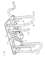
- Figure 1 is a perspective view of a device for the present inventions, in the "closed" position;
- Figure 2 is identical to Figure 1 but shows the device in an "open" position.
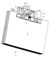
- Figure 3 shows the device of Figure 1 holding a stack of papers
- Figure 4 is an exploded view of the device shown in Figures 1 and 2
- Figures 5 and 6 are, respectively, a front elevation and a side elevation of the mechanism shown in Figures 1 and 2.
- Figure 7 is a plan view of the mechanism shown in Figures 1 and 2.
- Figure 8 is a plan view of a compressor bar for holding papers shown in Figure 3.
-
- Referring initially to Figure 1, there is shown a device for retaining a stack of papers in a file. The device includes a
base 10 made from pressed steel and including'holes 12 that accommodate rivets (not shown) for securing the device to a file. Tworings 14 extend from thebase 10, each ring being composed of apin 16 and anarched section 18.Additional pins 20 are secured to thebase 10 between therings 14. Thepins holes 19 in the base 10 (see Figure 4) and are welded in place on thebase 10. - The
arched sections 18 of the tworings 14 are joined together by acentral section 30, which is pivotally held on the base by two bent overtabs 31, which are pressed out from thebase 10. Such an arrangement allows thearched sections 18 and the connectingpart 30 to pivot about a horizontal axis extending between the twotabs 31. - The connecting
section 30 includes acrank section 32. Aleaf spring 34 is secured at one end (34') in aslot 36 in the base; theother end 34" engages underneath thecrank section 32 and tends to urge thecrank section 32 upwardly, causing thearched sections 18 to pivot about the horizontal axis extending between the twotabs 31 to open the rings. - A generally
upright wall 40 is also pressed out from thebase 10. Alever 42 is secured to thewall 40 by means of arivet 44 that passes through ahole 46 in thewall 40 and ahole 48 in thelever 42. The arrangement is such that therivet 44 allows thelever 42 to pivot about thewall 40. - The
lever 42 carries aroller 50 that is secured to it by afurther rivet 52 whose end is secured in ahole 54 in thelever 42. The roller engages the top of thecrank section 32 to control the opening and clothing of thearched section 18 of thering 14, as will be described later. - The tops of the
pins 16 have amale profile 60 that mate with a corresponding female profile at theend 62 of the arched sections 18 (see Figure 4); this allows a positive engagement between thepin 16 and thearched section 18 of eachring 14 and assists the alignment between thepin 16 and thearched section 18 of each ring so that paper cannot snag on the join between them. - The
lever 42 can be moved aboutrivet 44 between a horizontal position (shown in Figure 1) and an upwardly extending position shown in Figure 2. In the position shown in Figure 1, theroller 50 presses thecrank section 32 down against the action of thespring 34 to keep thearched sections 18 of each ring in the locked position abutting against thecorresponding pins 16 to form the closed rings shown in Figure 1. When thelever 42 is moved to the upwardly extended position shown in Figure 2, theroller 50 no longer presses down on thecrank section 32 and this allows thecrank section 32 to be moved upwardly byspring 34 into the open position shown in Figure 2. By pressing down on thelever 42, thecrank section 32 can be moved by theroller 50 against the action of thespring 34 into the closed position shown in Figure 1. - A stack of papers 22 (shown In Figure 3) having holes (not shown) in their margins can be threaded onto the
pins 16 and theadditional pins 20 when the rings are in their "open" position (shown in Figure 2). Once the stack of papers has been threaded on to thepins lever 42 can be depressed to the position shown in Figure 1 to hold the stack of papers captive on therings 14. The upper pages of the stack may be slid over thepins arched sections 18 so that papers lower down the stack can be exposed for easy reading. - A document compressor bar 24 (see Figures 3 and 8) may also be threaded onto the
pins openings pins rods 26 that grip thepins 16 when abutton 28 is depressed and release thepins 16 when the button is raised. The bar thus holds the papers in place and prevents them sliding up and down thepins button 28 is depressed (i.e. when the rods grip the pins 16) but the bar allows the papers to slide freely on the pins when the button is raised and the rods release their grip on thepins 16. Thebar 24 differs from a conventional compressor bar in having theadditional holes 29 to accommodate theadditional pins 18; thepins 16 pass through theholes 31. - The use of four
pins rings 14 is the same as that of a two pin device and is much simpler than that of a four pin device with four rings.
When reading the papers in the file, it is usual to slide a page that has just been read over the rings14 so that it is held on thearched section 18 rather than thepins arched section 18 must be slid back onto thepins pins 20 are exactly parallel with thepins 16, the central two marginal holes in the papers are directed onto the centraladditional pins 20 even though they have no correspondingarched sections 18 and accordingly the flipping of the papers back onto thepins
The term "ring" used in the present specification is intended to encompass both:
Claims (4)
- A device for retaining in a file a stack of papers that have holes in their margins, which device comprises:characterised in that the device further includes at least one additional pin that is also arranged to engage a hole in the margin of each paper but the said additional pin does not include a corresponding arched section for forming a closed loop.at least two rings secured to and extending upwardly from the base for engaging the marginal holes in the papers, each ring being composed of a pin and an arched section, the rings being arranged to engage holes in the margin of the papers anda mechanism for keeping the pin and the arched section of each ring in either a closed position in which the pin and the arched section of each ring abut each other and form a closed loop and an open position in which the pin and the arched section are separated to allow papers to be added to, or removed from, the rings;
- A device as claimed in claim 1, wherein the arched section of each ring is pivotally mounted and the mechanism includes means for urging the arched sections of the rings into the closed position and a spring that urges the arched sections into the open position when the lever is released.
- A device as claimed in claim 1, wherein the additional pins are located between the rings.
- A device as claimed in claim 1, wherein the additional pins are parallel with the pins of the rings.
Applications Claiming Priority (2)
| Application Number | Priority Date | Filing Date | Title |
|---|---|---|---|
| GB0005605 | 2000-03-08 | ||
| GBGB0005605.1A GB0005605D0 (en) | 2000-03-08 | 2000-03-08 | Device for retaining a stack of papers in a file |
Publications (2)
| Publication Number | Publication Date |
|---|---|
| EP1138524A2 true EP1138524A2 (en) | 2001-10-04 |
| EP1138524A3 EP1138524A3 (en) | 2002-01-16 |
Family
ID=9887230
Family Applications (1)
| Application Number | Title | Priority Date | Filing Date |
|---|---|---|---|
| EP00307808A Withdrawn EP1138524A3 (en) | 2000-03-08 | 2000-09-08 | File |
Country Status (9)
| Country | Link |
|---|---|
| EP (1) | EP1138524A3 (en) |
| JP (1) | JP2003525787A (en) |
| CN (1) | CN1154579C (en) |
| AU (1) | AU2343301A (en) |
| GB (1) | GB0005605D0 (en) |
| IL (1) | IL146360A0 (en) |
| NO (1) | NO20015451L (en) |
| PL (1) | PL351031A1 (en) |
| WO (1) | WO2001066363A1 (en) |
Cited By (2)
| Publication number | Priority date | Publication date | Assignee | Title |
|---|---|---|---|---|
| WO2009010050A2 (en) * | 2007-07-16 | 2009-01-22 | Volker Martin | Apparatus for filing perforated sheets of paper in a binder |
| CN102248835A (en) * | 2010-05-21 | 2011-11-23 | 武汉新芯集成电路制造有限公司 | Folder |
Families Citing this family (8)
| Publication number | Priority date | Publication date | Assignee | Title |
|---|---|---|---|---|
| AU2003272996A1 (en) * | 2003-10-14 | 2005-04-27 | Kokuyo Co., Ltd. | Binder and file |
| DE10353179B4 (en) * | 2003-11-13 | 2014-05-22 | Esselte Leitz Gmbh & Co. Kg | file mechanism |
| JP4637170B2 (en) * | 2005-03-25 | 2011-02-23 | 株式会社リヒトラブ | File binder binder |
| CN200992041Y (en) * | 2006-06-30 | 2007-12-19 | 华利五金公司 | Loose-leaf binder fastener |
| CN101125502A (en) * | 2006-08-15 | 2008-02-20 | 利高文具制造厂有限公司 | Lever clamp mechanism |
| CN101172435B (en) * | 2006-10-31 | 2010-08-04 | 利高文具制造厂有限公司 | Lever clamp mechanism |
| CN102887010B (en) * | 2008-07-17 | 2015-01-28 | 国际文具制造厂有限公司 | Paper keeping device |
| MX2011000627A (en) * | 2008-07-17 | 2011-02-25 | World Wide Stationery Mfg Co | A paper-retaining mechanism. |
Citations (3)
| Publication number | Priority date | Publication date | Assignee | Title |
|---|---|---|---|---|
| DE360649C (en) * | 1921-09-03 | 1922-10-05 | Soennecken Fa F | Letter folder with more than two alignment pins |
| DE853747C (en) * | 1944-04-06 | 1952-10-27 | Erwin Otto Haberfeld | Letter folder |
| US4415290A (en) * | 1981-01-27 | 1983-11-15 | King Jim Co., Ltd. | Binder assembly of the ring type |
Family Cites Families (3)
| Publication number | Priority date | Publication date | Assignee | Title |
|---|---|---|---|---|
| FR2583345B1 (en) * | 1985-06-14 | 1989-03-03 | Gerriet Jacques | RING FILER FOR PERFORATED SHEETS |
| EP0482354B1 (en) * | 1990-10-22 | 1995-02-01 | KOLOMAN HANDLER GESELLSCHAFT m.b.H. | Ring binder or writing board |
| DE4120716A1 (en) * | 1991-06-22 | 1992-12-24 | Leitz Fa Louis | LETTER FOLDER |
-
2000
- 2000-03-08 GB GBGB0005605.1A patent/GB0005605D0/en not_active Ceased
- 2000-09-08 EP EP00307808A patent/EP1138524A3/en not_active Withdrawn
- 2000-12-29 JP JP2001565194A patent/JP2003525787A/en active Pending
- 2000-12-29 AU AU23433/01A patent/AU2343301A/en not_active Abandoned
- 2000-12-29 WO PCT/CN2000/000741 patent/WO2001066363A1/en active Application Filing
- 2000-12-29 CN CNB008096090A patent/CN1154579C/en not_active Expired - Fee Related
- 2000-12-29 PL PL00351031A patent/PL351031A1/en not_active Application Discontinuation
- 2000-12-29 IL IL14636000A patent/IL146360A0/en unknown
-
2001
- 2001-11-07 NO NO20015451A patent/NO20015451L/en not_active Application Discontinuation
Patent Citations (3)
| Publication number | Priority date | Publication date | Assignee | Title |
|---|---|---|---|---|
| DE360649C (en) * | 1921-09-03 | 1922-10-05 | Soennecken Fa F | Letter folder with more than two alignment pins |
| DE853747C (en) * | 1944-04-06 | 1952-10-27 | Erwin Otto Haberfeld | Letter folder |
| US4415290A (en) * | 1981-01-27 | 1983-11-15 | King Jim Co., Ltd. | Binder assembly of the ring type |
Cited By (3)
| Publication number | Priority date | Publication date | Assignee | Title |
|---|---|---|---|---|
| WO2009010050A2 (en) * | 2007-07-16 | 2009-01-22 | Volker Martin | Apparatus for filing perforated sheets of paper in a binder |
| WO2009010050A3 (en) * | 2007-07-16 | 2009-10-15 | Volker Martin | Apparatus for filing perforated sheets of paper in a binder |
| CN102248835A (en) * | 2010-05-21 | 2011-11-23 | 武汉新芯集成电路制造有限公司 | Folder |
Also Published As
| Publication number | Publication date |
|---|---|
| IL146360A0 (en) | 2002-07-25 |
| NO20015451L (en) | 2002-01-07 |
| WO2001066363A1 (en) | 2001-09-13 |
| CN1154579C (en) | 2004-06-23 |
| EP1138524A3 (en) | 2002-01-16 |
| CN1358144A (en) | 2002-07-10 |
| NO20015451D0 (en) | 2001-11-07 |
| JP2003525787A (en) | 2003-09-02 |
| AU2343301A (en) | 2001-09-17 |
| PL351031A1 (en) | 2003-03-10 |
| GB0005605D0 (en) | 2000-05-03 |
Similar Documents
| Publication | Publication Date | Title |
|---|---|---|
| US7534064B2 (en) | Ring mechanism biased to closed and locked position | |
| US6036394A (en) | Ring metals with linkage locking device | |
| US8038361B2 (en) | Ready lock ring binder mechanism | |
| US7828491B2 (en) | Travel bar for use with a ring mechanism | |
| US5816729A (en) | Ring binder with low profile ring metal | |
| KR100669406B1 (en) | Device for retaining a stack of papers in a file | |
| EP1908603A2 (en) | A ring binder mechanism with a sliding hinge plate | |
| EP1138524A2 (en) | File | |
| US20090274509A1 (en) | Ring binder mechanism with sliding hinge plate | |
| US6394684B2 (en) | Fastener for a folder | |
| EP0962336A1 (en) | Device for retaining a stack of papers | |
| US20080175652A1 (en) | Ring Binder Mechanism | |
| US20080286035A1 (en) | Ring Binder Mechanism Having Blocking Device | |
| US7758272B2 (en) | Binding device for files and binders | |
| US20090041531A1 (en) | Lever-arch type file mechanism | |
| CA2463393C (en) | Ring mechanism having blunt ends | |
| GB2587439A (en) | A document file | |
| WO2008155577A1 (en) | Punch file | |
| US6971815B1 (en) | Binder ring clamp assembly | |
| US2255537A (en) | Loose-leaf binder | |
| EP1997645A2 (en) | A compressor bar for a lever-arch type file mechanism | |
| EP2479039A2 (en) | Paper-retaining mechanism | |
| EP1572469A2 (en) | Device and method for tying papers | |
| CA2272498A1 (en) | A housing for a ring binder mechanism | |
| US20050025562A1 (en) | Document binder |
Legal Events
| Date | Code | Title | Description |
|---|---|---|---|
| PUAI | Public reference made under article 153(3) epc to a published international application that has entered the european phase |
Free format text: ORIGINAL CODE: 0009012 |
|
| AK | Designated contracting states |
Kind code of ref document: A2 Designated state(s): AT BE CH CY DE DK ES FI FR GB GR IE IT LI LU MC NL PT SE |
|
| AX | Request for extension of the european patent |
Free format text: AL;LT;LV;MK;RO;SI |
|
| PUAL | Search report despatched |
Free format text: ORIGINAL CODE: 0009013 |
|
| AK | Designated contracting states |
Kind code of ref document: A3 Designated state(s): AT BE CH CY DE DK ES FI FR GB GR IE IT LI LU MC NL PT SE |
|
| AX | Request for extension of the european patent |
Free format text: AL;LT;LV;MK;RO;SI |
|
| 17P | Request for examination filed |
Effective date: 20020716 |
|
| AKX | Designation fees paid |
Free format text: AT BE CH CY DE DK ES FI FR GB GR IE IT LI LU MC NL PT SE |
|
| STAA | Information on the status of an ep patent application or granted ep patent |
Free format text: STATUS: THE APPLICATION IS DEEMED TO BE WITHDRAWN |
|
| 18D | Application deemed to be withdrawn |
Effective date: 20030402 |