EP1138262A2 - Tomographic ultrasonic diagnostic apparatus - Google Patents
Tomographic ultrasonic diagnostic apparatus Download PDFInfo
- Publication number
- EP1138262A2 EP1138262A2 EP01302344A EP01302344A EP1138262A2 EP 1138262 A2 EP1138262 A2 EP 1138262A2 EP 01302344 A EP01302344 A EP 01302344A EP 01302344 A EP01302344 A EP 01302344A EP 1138262 A2 EP1138262 A2 EP 1138262A2
- Authority
- EP
- European Patent Office
- Prior art keywords
- ultrasonic
- view
- field
- frequency
- transmitting
- Prior art date
- Legal status (The legal status is an assumption and is not a legal conclusion. Google has not performed a legal analysis and makes no representation as to the accuracy of the status listed.)
- Granted
Links
Images



Classifications
-
- G—PHYSICS
- G01—MEASURING; TESTING
- G01S—RADIO DIRECTION-FINDING; RADIO NAVIGATION; DETERMINING DISTANCE OR VELOCITY BY USE OF RADIO WAVES; LOCATING OR PRESENCE-DETECTING BY USE OF THE REFLECTION OR RERADIATION OF RADIO WAVES; ANALOGOUS ARRANGEMENTS USING OTHER WAVES
- G01S7/00—Details of systems according to groups G01S13/00, G01S15/00, G01S17/00
- G01S7/52—Details of systems according to groups G01S13/00, G01S15/00, G01S17/00 of systems according to group G01S15/00
- G01S7/52017—Details of systems according to groups G01S13/00, G01S15/00, G01S17/00 of systems according to group G01S15/00 particularly adapted to short-range imaging
- G01S7/52053—Display arrangements
- G01S7/52057—Cathode ray tube displays
- G01S7/5206—Two-dimensional coordinated display of distance and direction; B-scan display
-
- A—HUMAN NECESSITIES
- A61—MEDICAL OR VETERINARY SCIENCE; HYGIENE
- A61B—DIAGNOSIS; SURGERY; IDENTIFICATION
- A61B8/00—Diagnosis using ultrasonic, sonic or infrasonic waves
- A61B8/13—Tomography
- A61B8/14—Echo-tomography
-
- G—PHYSICS
- G01—MEASURING; TESTING
- G01S—RADIO DIRECTION-FINDING; RADIO NAVIGATION; DETERMINING DISTANCE OR VELOCITY BY USE OF RADIO WAVES; LOCATING OR PRESENCE-DETECTING BY USE OF THE REFLECTION OR RERADIATION OF RADIO WAVES; ANALOGOUS ARRANGEMENTS USING OTHER WAVES
- G01S15/00—Systems using the reflection or reradiation of acoustic waves, e.g. sonar systems
- G01S15/88—Sonar systems specially adapted for specific applications
- G01S15/89—Sonar systems specially adapted for specific applications for mapping or imaging
- G01S15/8906—Short-range imaging systems; Acoustic microscope systems using pulse-echo techniques
- G01S15/895—Short-range imaging systems; Acoustic microscope systems using pulse-echo techniques characterised by the transmitted frequency spectrum
-
- G—PHYSICS
- G01—MEASURING; TESTING
- G01S—RADIO DIRECTION-FINDING; RADIO NAVIGATION; DETERMINING DISTANCE OR VELOCITY BY USE OF RADIO WAVES; LOCATING OR PRESENCE-DETECTING BY USE OF THE REFLECTION OR RERADIATION OF RADIO WAVES; ANALOGOUS ARRANGEMENTS USING OTHER WAVES
- G01S15/00—Systems using the reflection or reradiation of acoustic waves, e.g. sonar systems
- G01S15/88—Sonar systems specially adapted for specific applications
- G01S15/89—Sonar systems specially adapted for specific applications for mapping or imaging
- G01S15/8906—Short-range imaging systems; Acoustic microscope systems using pulse-echo techniques
- G01S15/895—Short-range imaging systems; Acoustic microscope systems using pulse-echo techniques characterised by the transmitted frequency spectrum
- G01S15/8952—Short-range imaging systems; Acoustic microscope systems using pulse-echo techniques characterised by the transmitted frequency spectrum using discrete, multiple frequencies
Definitions
- the present invention relates to an ultrasonic diagnostic apparatus for transmitting an ultrasonic wave to a living body and receiving a wave reflected by the living body to produce a tomographic image from the reflected wave.
- An ultrasonic diagnostic apparatus has been conventionally used for medical diagnosis for the purpose of producing organic information of a living body or a patient.
- This ultrasonic diagnostic apparatus transmits an ultrasonic pulse into an organ of the patient through an ultrasonic probe and receives the reflected wave from a boundary surface between tissues different in acoustic impedance through the ultrasonic probe to convert the reflected wave into an electric signal. Further, the ultrasonic diagnostic apparatus displays an ultrasonic tomographic image on a monitor on the basis of the electric signal.
- the depth from the organic surface in which an ultrasonic tomographic image can be produced namely, a limit of visible depth becomes shallower the higher frequency of ultrasonic wave is used for diagnosis because an ultrasonic wave is heavily absorbed by the organ in proportional to the frequency of the ultrasonic wave.
- a system controller 112 controls a drive frequency for an ultrasonic probe 115 according to a focus position, a color display area or a Doppler signal detection position. According to this apparatus, the frequency of the ultrasonic wave is changed according to the focus position, the color display area or the Doppler signal detection position.
- the conventional apparatus as set forth above has disadvantages that even if the depth of field of view is set deep in order to display the diagnostic target region, the visual depth limit does not change because the transmitting frequency does not change and as a result, it is difficult to produce organic information on the area surrounding the diagnostic target region.
- the conventional apparatus has disadvantages that even if the depth of field of view is set shallow in order to display the diagnostic target region, the resolution of the diagnostic target region does not change because the transmitting frequency does not change and as a result, it is difficult to produce an image of high resolution.
- the conventional apparatus has disadvantages that even if the enlargingly displayed area of field of view is set deep in order to enlargingly display the diagnostic target region, the visible depth limit does not change because the transmitting frequency does not change and as a result, it is difficult to produce organic information on the area surrounding the enlargingly displayed area of field of view.
- the conventional apparatus has disadvantages that even if the enlargingly displayed area of field of view is set shallow in order to enlargingly display the diagnostic target region, the resolution of the enlargingly displayed area of field of view does not change because the transmitting frequency does not change and as a result, it is difficult to produce an image of high resolution.
- the conventional apparatus has disadvantages that even if the field of view is changed, the transmitting frequency cannot be changed without changing the focus position, the color display area or the Doppler signal detection position in the field of view.
- the ultrasonic diagnostic apparatus of the present invention comprises ultrasonic transmitting/receiving means for transmitting an ultrasonic wave to a living body and receiving a wave reflected from the living body to convert the reflected wave into an electric signal, control means for controlling the frequency of the ultrasonic wave to be transmitted by the ultrasonic transmitting/receiving means according to a field of view, and display means for displaying a diagnostic image on the basis of the electric signal from the ultrasonic transmitting/receiving means.
- the frequency of the ultrasonic wave to be transmitted by the ultrasonic transmitting/receiving means can be automatically changed according to the field of view.
- control means may be arranged to control the frequency of the ultrasonic wave to be transmitted by the ultrasonic transmitting/receiving means according to the depth of field of view.
- the frequency of the ultrasonic wave to be transmitted by the ultrasonic transmitting/receiving means can be automatically changed according to the depth of field of view.
- control means may be arranged to control the frequency of the ultrasonic wave to be transmitted by the ultrasonic transmitting/receiving means according to the position of the enlargingly displayed area of field of view.
- the frequency of the ultrasonic wave to be transmitted by the ultrasonic transmitting/receiving means can be automatically changed according to the position of the enlargingly displayed area of field of view.
- the ultrasonic diagnostic apparatus in addition to an arrangement comprising ultrasonic transmitting/receiving means for transmitting an ultrasonic wave to a living body and receiving a wave reflected from the living body to convert the reflected wave into an electric signal, control means for controlling the frequency of the ultrasonic wave to be transmitted by the ultrasonic transmitting/receiving means according to a field of view, and display means for displaying a diagnostic image on the basis of the electric signal from the ultrasonic transmitting/receiving means, the ultrasonic diagnostic apparatus may be arranged to further include a rewritable retention table for diagnostic condition data.
- a user can change easily such a setting that the frequency of the ultrasonic wave to be transmitted by the ultrasonic transmitting/receiving means can be automatically changed according to the field of view.
- Fig. 1 shows a construction view of the first embodiment of the present invention.
- Fig. 2 show a view for illustrating the operation of the present invention.
- Fig. 3 shows a flowchart for illustrating the operation of the present invention.
- Fig. 4 shows a construction view of the second embodiment of the present invention.
- Fig. 5 shows a construction view of prior art.
- Fig. 1 shows the first embodiment of the present invention.
- An operation panel 11 is adapted to allow a user to set different diagnostic conditions. For example, the user can make selection of diagnostic modes, etc., and settings of the depth of field of view, the enlargingly displayed area of field of view and the like.
- the information set through the operation panel 11 is supplied to a system controller 12.
- the system controller 12 is adapted to control the whole system, particularly, to determine the frequency of the ultrasonic wave to be transmitted from an ultrasonic probe 14 according to the field of view set through the operation panel 11.
- the system controller 12 determines to transmit an ultrasonic wave of low frequency when the depth of field of view is set to deep level and to transmit an ultrasonic wave of high frequency when the depth of field of view is set to shallow level.
- the ultrasonic probe used in this embodiment has a wide frequency range or ultrasonic elements of two or more different types, for example, the ultrasonic probe is designed so that it can transmit and receive ultrasonic waves of 5.0-7.5 MHz.
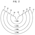
- Fig. 2 shows the case of mechanical sector.
- the ultrasonic waves of three different frequencies of 5.0, 6.0 and 7.5 MHz are transmitted.
- reference numeral 20 designates the maximum field of view when the ultrasonic wave of 5.0 MHz is transmitted.
- Arc 21 shows the maximum depth of field of view when the ultrasonic wave 5.0 MHz is transmitted.
- Arcs 22, 23 and 24 show the limit of visible depth when the frequency of the ultrasonic wave is 5.0, 6.0 and 7.5 MHz respectively.
- Reference numerals 31, 32, 33 and 34 designate respectively the areas surrounded by these arcs 21, 22, 23 and 24.
- the ultrasonic wave of 5.0 MHz is transmitted when the depth of field of view is set to the areas 31 and 32
- the ultrasonic wave of 6.0 MHz is transmitted when the depth of field of view is set to the area 33
- the ultrasonic wave of 7.5 MHz is transmitted when the depth of field of view is set to the area 34.
- the limit of visible depth is the arc 23 in Fig. 2 when the ultrasonic wave of 6.0 MHz is transmitted.
- the drive frequency for the ultrasonic probe 14 is determined as set forth above, whereby the ultrasonic wave of 5.0 MHz is transmitted when the depth of field of view is set in the area 32, and as a result, the limit of visible depth becomes the arc 22. Consequently, the field of view is extended by the portion of the area 32 over the conventional apparatus.
- the information concerning the tissue surrounding the diagnostic target region can be obtained as an image to improve the accuracy of the diagnosis. If the depth of field of view is set to the shallow level, the ultrasonic wave of high frequency is transmitted. As a result, the resolution is improved over the conventional apparatus.
- the case of mechanical sector probe has been described hereinbefore and alternatively, an array probe and the like can be used. There is no limitation on the type of ultrasonic probe.
- a transmitting circuit 13 generates a master signal therein and converts a trigger signal of the frequency determined by the system controller 12 into a pulse signal of high voltage on the basis of the frequency of the master signal and then the pulse signal is applied to the ultrasonic probe 14.
- the ultrasonic probe 14 transmits an ultrasonic wave into the living body or the organ of the patient in response to the pulse signal and receive a wave reflected from the organ of the patient and converts the reflected wave to an electric signal.
- This electric signal is input to a receiving circuit 15 in a back stage.
- the receiving circuit 15 applys the predetermined amplification and detection, etc. to the electric signal and supplies the signal to an image processing unit 16.
- the image processing unit 16 applies the predetermined processing to the signal from the receiving circuit 15 and displays the signal on a display unit 17 as a diagnostic image.
- the system controller 12 determines the driving frequency for the ultrasonic probe 14 in response to the depth of field of view. For example, the frequency is determined to be set to 5.0 MHz if the set depth of field of view is in the area 32 in Fig. 2.
- the information concerning the frequency is supplied to the transmitting circuit 13.
- the transmitting circuit 13 converts the trigger signal of the frequency determined by the system controller 12 into the pulse signal of high voltage and then, the pulse signal is applied to the ultrasonic probe 14.
- the ultrasonic wave transmitted from the ultrasonic probe 14 in response to the pulse signal is reflected by the different tissues of the patient body and received by the ultrasonic probe 14 and then, converted into an electric signal.
- This electric signal is input to the receiving circuit 15 in the back stage.
- the receiving circuit 15 applies amplification and detection, etc. to the electric signal and supplies the electric signal to the image processing unit 16.
- the image processing unit 16 implements processing such as scan transform or brightness transform to the electric signal and supplies the processed electric signal to the display unit 17 as image data.
- the display unit 17 displays the image data as an ultrasonic diagnostic image.
- the advantage of the apparatus set forth above is that if the depth of field of view is set according to the position of diagnostic target region, an ultrasonic wave which frequency corresponds to the depth of field of view is transmitted, and therefore, information concerning the area surrounding the diagnostic target region is obtained, and if the depth of field of view is set shallow, an image of high resolution can be obtained.
- the advantage of the apparatus is that an ultrasonic wave which frequency corresponds to the depth of field of view is transmitted and therefore, if the depth of field of view is set deep, the limit of visible depth becomes deep whereby it becomes easy to see the diagnostic image, and as a result, the accuracy of diagnosis is improved.
- the advantage of the apparatus is that an ultrasonic wave which frequency corresponds to the position of enlargingly displayed area of field of view is transmitted, and therefore, if the enlargingly displayed area of field of view is set shallow, an image of high resolution can be obtained.
- the advantage of the apparatus is that an ultrasonic wave which frequency corresponds to the position of the enlargingly displayed area of field of view is transmitted and therefore, if the enlargingly displayed area of field of view is set deep, the limit of visible depth becomes deep, whereby it becomes easy to see the enlargingly displayed diagnostic image, and as a result, the accuracy of diagnosis is improved.
- ultrasonic waves of three different frequencies are transmitted.
- it is intended to include two or more different frequencies.
- it is not intended to limit the present invention to the embodiment described hereinbefore. Many modifications are possible within the scope of the present invention defined in the appended claims.
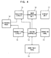
- the second embodiment of the present invention will be now described using Fig. 4.
- the second embodiment of the present invention is different from the first embodiment as set forth above in further including a rewritable table 18.
- the content of the table displayed on the TV moniter is easily rewritable by the user through the operation panel 11.
- the system controller 12 checks the rewritable table 18 on the basis of the information concerning the field of view set through the operation panel 11 and controls the transmitting circuit 13 to change the frequency of the ultrasonic wave to be transmitted.
- Control of the frequency of the ultrasonic wave to be transmitted with respect to the depth of field of view will be hereinafter described by way of example.
- Table 1 shows one example of the contents of the rewritable table 18.
- Depth Of Field Of View Frequency Of Ultrasonic Wave To Be Transmitted from 20 mm or more to less than 50 mm 7.5MHz from 50 mm or more to less than 120 mm 6.0MHz 120 mm or more 5.0MHz
- the value of the depth of field of view shown in Table 1 is displayed on the display unit 17 whereby the user can easily rewrite the value of the depth of field of view through the operation panel 11.
- the degree of absorption of ultrasonic wave into the patient body varies with type of the patient body.
- the degree of absorption of ultrasonic wave into the patient body varies with different target organs in the diagnostic field such as abdominal area, obstetric area, etc. Since the degree of absorption of ultrasonic wave into patient body changes, the limit of visible depth also changes even if the transmitting frequency is constant.
- the user can easily change the setting wherein the frequency of the ultrasonic wave to be transmitted from the ultrasonic transmitting/receiving means according to the field of view is automatically changed, and therefore, it is easy to compensate in response to the change of limit of visible depth.
- the advantage of the present invention is that if the depth of field of view is set according to the position of diagnostic target region, an ultrasonic wave which frequency corresponds to the depth of field of view is transmitted, and therefore, information concerning the area surrounding the diagnostic target region is obtained, and if the depth of field of view is set shallow, an image of high resolution can be obtained.
- the advantage of the present invention is that an ultrasonic wave which frequency corresponds to the depth of field of view is transmitted and therefore, if the depth of field of view is set deep, the limit of visible depth becomes deep whereby it becomes easy to see the diagnostic image, and as a result, the accuracy of diagnosis is improved.
- the advantage of the present invention is that an ultrasonic wave which frequency corresponds to the position of enlargingly displayed area of field of view is transmitted, and therefore, if enlargingly displayed area of field of view is set shallow, an image of high resolution can be obtained.
- the advantage of the present invention is that an ultrasonic wave which frequency corresponds to the position of the enlargingly displayed area of field of view is transmitted and therefore, if the enlargingly displayed area of field of view is set deep, the limit of visible depth becomes deep, whereby it becomes easy to see the enlargingly displayed diagnostic image, and as a result, the accuracy of diagnosis is improved.
- the user can easily change the setting wherein the frequency of the ultrasonic wave to be transmitted from the ultrasonic transmitting/receiving means according to the field of view is automatically changed, and therefore, it is easy to compensate in response to the change of limit of visible depth.
Landscapes
- Engineering & Computer Science (AREA)
- Physics & Mathematics (AREA)
- Radar, Positioning & Navigation (AREA)
- Remote Sensing (AREA)
- Health & Medical Sciences (AREA)
- Life Sciences & Earth Sciences (AREA)
- Acoustics & Sound (AREA)
- Computer Networks & Wireless Communication (AREA)
- General Physics & Mathematics (AREA)
- Radiology & Medical Imaging (AREA)
- Molecular Biology (AREA)
- Pathology (AREA)
- Biophysics (AREA)
- Biomedical Technology (AREA)
- Heart & Thoracic Surgery (AREA)
- Medical Informatics (AREA)
- Nuclear Medicine, Radiotherapy & Molecular Imaging (AREA)
- Surgery (AREA)
- Animal Behavior & Ethology (AREA)
- General Health & Medical Sciences (AREA)
- Public Health (AREA)
- Veterinary Medicine (AREA)
- Ultra Sonic Daignosis Equipment (AREA)
- Investigating Or Analyzing Materials By The Use Of Ultrasonic Waves (AREA)
Abstract
Description
- The present invention relates to an ultrasonic diagnostic apparatus for transmitting an ultrasonic wave to a living body and receiving a wave reflected by the living body to produce a tomographic image from the reflected wave.
- An ultrasonic diagnostic apparatus has been conventionally used for medical diagnosis for the purpose of producing organic information of a living body or a patient. This ultrasonic diagnostic apparatus transmits an ultrasonic pulse into an organ of the patient through an ultrasonic probe and receives the reflected wave from a boundary surface between tissues different in acoustic impedance through the ultrasonic probe to convert the reflected wave into an electric signal. Further, the ultrasonic diagnostic apparatus displays an ultrasonic tomographic image on a monitor on the basis of the electric signal.
- In such a ultrasonic diagnostic apparatus, the depth from the organic surface in which an ultrasonic tomographic image can be produced, namely, a limit of visible depth becomes shallower the higher frequency of ultrasonic wave is used for diagnosis because an ultrasonic wave is heavily absorbed by the organ in proportional to the frequency of the ultrasonic wave. However, it is desirable to use a high frequency wave in order to produce an ultrasonic tomographic image of a high resolution.
- In transmission of an ultrasonic wave, it is desirable to increase the frequency of the ultrasonic wave to be transmitted in order to increase the resolution of a target region for diagnosis. However, even if the depth set to be displayed on the monitor, namely, the depth of field of view is set deep, the limit of visible depth is constant because the frequency of the ultrasonic wave to be transmitted is constant.
- Conventionally, the ultrasonic diagnostic apparatus as described in Japanese Patent Public Disclosure No. 6-54850 is well known. The construction of this apparatus is shown in Fig. 5. In Fig. 5, a
system controller 112 controls a drive frequency for anultrasonic probe 115 according to a focus position, a color display area or a Doppler signal detection position. According to this apparatus, the frequency of the ultrasonic wave is changed according to the focus position, the color display area or the Doppler signal detection position. - However, the conventional apparatus as set forth above has disadvantages that even if the depth of field of view is set deep in order to display the diagnostic target region, the visual depth limit does not change because the transmitting frequency does not change and as a result, it is difficult to produce organic information on the area surrounding the diagnostic target region.
- Further, the conventional apparatus has disadvantages that even if the depth of field of view is set shallow in order to display the diagnostic target region, the resolution of the diagnostic target region does not change because the transmitting frequency does not change and as a result, it is difficult to produce an image of high resolution.
- Further, the conventional apparatus has disadvantages that even if the enlargingly displayed area of field of view is set deep in order to enlargingly display the diagnostic target region, the visible depth limit does not change because the transmitting frequency does not change and as a result, it is difficult to produce organic information on the area surrounding the enlargingly displayed area of field of view.
- Further, the conventional apparatus has disadvantages that even if the enlargingly displayed area of field of view is set shallow in order to enlargingly display the diagnostic target region, the resolution of the enlargingly displayed area of field of view does not change because the transmitting frequency does not change and as a result, it is difficult to produce an image of high resolution.
- Further, the conventional apparatus has disadvantages that even if the field of view is changed, the transmitting frequency cannot be changed without changing the focus position, the color display area or the Doppler signal detection position in the field of view.
- It is an object of the present invention to solve the problem set forth above in the prior art and to provide an improved ultrasonic diagnostic apparatus capable of automatically changing an ultrasonic wave to be transmitted according to the field of view.
- The ultrasonic diagnostic apparatus of the present invention comprises ultrasonic transmitting/receiving means for transmitting an ultrasonic wave to a living body and receiving a wave reflected from the living body to convert the reflected wave into an electric signal, control means for controlling the frequency of the ultrasonic wave to be transmitted by the ultrasonic transmitting/receiving means according to a field of view, and display means for displaying a diagnostic image on the basis of the electric signal from the ultrasonic transmitting/receiving means. In this arrangement, the frequency of the ultrasonic wave to be transmitted by the ultrasonic transmitting/receiving means can be automatically changed according to the field of view.
- In the ultrasonic diagnostic apparatus of the present invention, the control means may be arranged to control the frequency of the ultrasonic wave to be transmitted by the ultrasonic transmitting/receiving means according to the depth of field of view. In this arrangement, the frequency of the ultrasonic wave to be transmitted by the ultrasonic transmitting/receiving means can be automatically changed according to the depth of field of view.
- In the ultrasonic diagnostic apparatus of the present invention, the control means may be arranged to control the frequency of the ultrasonic wave to be transmitted by the ultrasonic transmitting/receiving means according to the position of the enlargingly displayed area of field of view. In this arrangement, the frequency of the ultrasonic wave to be transmitted by the ultrasonic transmitting/receiving means can be automatically changed according to the position of the enlargingly displayed area of field of view.
- In the ultrasonic diagnostic apparatus of the present invention, in addition to an arrangement comprising ultrasonic transmitting/receiving means for transmitting an ultrasonic wave to a living body and receiving a wave reflected from the living body to convert the reflected wave into an electric signal, control means for controlling the frequency of the ultrasonic wave to be transmitted by the ultrasonic transmitting/receiving means according to a field of view, and display means for displaying a diagnostic image on the basis of the electric signal from the ultrasonic transmitting/receiving means, the ultrasonic diagnostic apparatus may be arranged to further include a rewritable retention table for diagnostic condition data. In the arrangement, a user can change easily such a setting that the frequency of the ultrasonic wave to be transmitted by the ultrasonic transmitting/receiving means can be automatically changed according to the field of view.
- Particular embodiments will now be described with reference to the accompanying drawings; in which:-
- Fig. 1 shows a construction view of the first embodiment of the present invention.
- Fig. 2 show a view for illustrating the operation of the present invention.
- Fig. 3 shows a flowchart for illustrating the operation of the present invention.
- Fig. 4 shows a construction view of the second embodiment of the present invention.
- Fig. 5 shows a construction view of prior art.
- The embodiments of the present invention will be descizbed hereinafter using the drawings. Fig. 1 shows the first embodiment of the present invention. An
operation panel 11 is adapted to allow a user to set different diagnostic conditions. For example, the user can make selection of diagnostic modes, etc., and settings of the depth of field of view, the enlargingly displayed area of field of view and the like. The information set through theoperation panel 11 is supplied to asystem controller 12. - The
system controller 12 is adapted to control the whole system, particularly, to determine the frequency of the ultrasonic wave to be transmitted from anultrasonic probe 14 according to the field of view set through theoperation panel 11. Thesystem controller 12 determines to transmit an ultrasonic wave of low frequency when the depth of field of view is set to deep level and to transmit an ultrasonic wave of high frequency when the depth of field of view is set to shallow level. The ultrasonic probe used in this embodiment has a wide frequency range or ultrasonic elements of two or more different types, for example, the ultrasonic probe is designed so that it can transmit and receive ultrasonic waves of 5.0-7.5 MHz. - One example of the method for determining the ultrasonic wave frequency set forth above will be described with reference to Figs. 2 and 3. Fig. 2 shows the case of mechanical sector. In the present embodiment, the ultrasonic waves of three different frequencies of 5.0, 6.0 and 7.5 MHz are transmitted. In Fig. 2,
reference numeral 20 designates the maximum field of view when the ultrasonic wave of 5.0 MHz is transmitted. Arc 21 shows the maximum depth of field of view when the ultrasonic wave 5.0 MHz is transmitted.Arcs Reference numerals arcs areas area 33, the ultrasonic wave of 7.5 MHz is transmitted when the depth of field of view is set to thearea 34. - In conventional case. the limit of visible depth is the
arc 23 in Fig. 2 when the ultrasonic wave of 6.0 MHz is transmitted. In the present invention, the drive frequency for theultrasonic probe 14 is determined as set forth above, whereby the ultrasonic wave of 5.0 MHz is transmitted when the depth of field of view is set in thearea 32, and as a result, the limit of visible depth becomes thearc 22. Consequently, the field of view is extended by the portion of thearea 32 over the conventional apparatus. The information concerning the tissue surrounding the diagnostic target region can be obtained as an image to improve the accuracy of the diagnosis. If the depth of field of view is set to the shallow level, the ultrasonic wave of high frequency is transmitted. As a result, the resolution is improved over the conventional apparatus. The case of mechanical sector probe has been described hereinbefore and alternatively, an array probe and the like can be used. There is no limitation on the type of ultrasonic probe. - A transmitting
circuit 13 generates a master signal therein and converts a trigger signal of the frequency determined by thesystem controller 12 into a pulse signal of high voltage on the basis of the frequency of the master signal and then the pulse signal is applied to theultrasonic probe 14. Theultrasonic probe 14 transmits an ultrasonic wave into the living body or the organ of the patient in response to the pulse signal and receive a wave reflected from the organ of the patient and converts the reflected wave to an electric signal. This electric signal is input to areceiving circuit 15 in a back stage. Thereceiving circuit 15 applys the predetermined amplification and detection, etc. to the electric signal and supplies the signal to animage processing unit 16. Theimage processing unit 16 applies the predetermined processing to the signal from thereceiving circuit 15 and displays the signal on adisplay unit 17 as a diagnostic image. The operation of the ultrasonic diagnostic apparatus set forth above will be described hereinafter. - A case where B mode is selected through the
operation panel 11 will be described. When the depth of field of view is set through theoperation panel 14, the information concerning the set depth of field of view is supplied to thesystem controller 12. Thesystem controller 12 determines the driving frequency for theultrasonic probe 14 in response to the depth of field of view. For example, the frequency is determined to be set to 5.0 MHz if the set depth of field of view is in thearea 32 in Fig. 2. The information concerning the frequency is supplied to the transmittingcircuit 13. The transmittingcircuit 13 converts the trigger signal of the frequency determined by thesystem controller 12 into the pulse signal of high voltage and then, the pulse signal is applied to theultrasonic probe 14. The ultrasonic wave transmitted from theultrasonic probe 14 in response to the pulse signal is reflected by the different tissues of the patient body and received by theultrasonic probe 14 and then, converted into an electric signal. This electric signal is input to the receivingcircuit 15 in the back stage. The receivingcircuit 15 applies amplification and detection, etc. to the electric signal and supplies the electric signal to theimage processing unit 16. Theimage processing unit 16 implements processing such as scan transform or brightness transform to the electric signal and supplies the processed electric signal to thedisplay unit 17 as image data. Thedisplay unit 17 displays the image data as an ultrasonic diagnostic image. - The advantage of the apparatus set forth above is that if the depth of field of view is set according to the position of diagnostic target region, an ultrasonic wave which frequency corresponds to the depth of field of view is transmitted, and therefore, information concerning the area surrounding the diagnostic target region is obtained, and if the depth of field of view is set shallow, an image of high resolution can be obtained.
- Further, the advantage of the apparatus is that an ultrasonic wave which frequency corresponds to the depth of field of view is transmitted and therefore, if the depth of field of view is set deep, the limit of visible depth becomes deep whereby it becomes easy to see the diagnostic image, and as a result, the accuracy of diagnosis is improved.
- Further, the advantage of the apparatus is that an ultrasonic wave which frequency corresponds to the position of enlargingly displayed area of field of view is transmitted, and therefore, if the enlargingly displayed area of field of view is set shallow, an image of high resolution can be obtained.
- Further, the advantage of the apparatus is that an ultrasonic wave which frequency corresponds to the position of the enlargingly displayed area of field of view is transmitted and therefore, if the enlargingly displayed area of field of view is set deep, the limit of visible depth becomes deep, whereby it becomes easy to see the enlargingly displayed diagnostic image, and as a result, the accuracy of diagnosis is improved.
- According to the embodiment as described hereinbefore, ultrasonic waves of three different frequencies are transmitted. However, it is intended to include two or more different frequencies. Further, it is not intended to limit the present invention to the embodiment described hereinbefore. Many modifications are possible within the scope of the present invention defined in the appended claims.
- The second embodiment of the present invention will be now described using Fig. 4. As shown in Fig. 4, the second embodiment of the present invention is different from the first embodiment as set forth above in further including a rewritable table 18. The content of the table displayed on the TV moniter is easily rewritable by the user through the
operation panel 11. Thesystem controller 12 checks the rewritable table 18 on the basis of the information concerning the field of view set through theoperation panel 11 and controls the transmittingcircuit 13 to change the frequency of the ultrasonic wave to be transmitted. - Control of the frequency of the ultrasonic wave to be transmitted with respect to the depth of field of view will be hereinafter described by way of example.
- Table 1 shows one example of the contents of the rewritable table 18.
Depth Of Field Of View Frequency Of Ultrasonic Wave To Be Transmitted from 20 mm or more to less than 50 mm 7.5MHz from 50 mm or more to less than 120 mm 6.0MHz 120 mm or more 5.0MHz - The value of the depth of field of view shown in Table 1 is displayed on the
display unit 17 whereby the user can easily rewrite the value of the depth of field of view through theoperation panel 11. - The degree of absorption of ultrasonic wave into the patient body varies with type of the patient body. The degree of absorption of ultrasonic wave into the patient body varies with different target organs in the diagnostic field such as abdominal area, obstetric area, etc. Since the degree of absorption of ultrasonic wave into patient body changes, the limit of visible depth also changes even if the transmitting frequency is constant.
- According to this construction, the user can easily change the setting wherein the frequency of the ultrasonic wave to be transmitted from the ultrasonic transmitting/receiving means according to the field of view is automatically changed, and therefore, it is easy to compensate in response to the change of limit of visible depth.
- It is possible to rewrite the value of transmitting frequency and keep storing the combination of the values. In the Table, three different ranges are set, but it is possible to set the ranges more finely. Control of the frequency of the ultrasonic wave to be transmitted is made not only in response to the depth of field of view but also in other setting such as in response to the position of the enlargingly displayed area of field of view, etc.
- As described in detail above, the advantage of the present invention is that if the depth of field of view is set according to the position of diagnostic target region, an ultrasonic wave which frequency corresponds to the depth of field of view is transmitted, and therefore, information concerning the area surrounding the diagnostic target region is obtained, and if the depth of field of view is set shallow, an image of high resolution can be obtained.
- Further, the advantage of the present invention is that an ultrasonic wave which frequency corresponds to the depth of field of view is transmitted and therefore, if the depth of field of view is set deep, the limit of visible depth becomes deep whereby it becomes easy to see the diagnostic image, and as a result, the accuracy of diagnosis is improved.
- Further, the advantage of the present invention is that an ultrasonic wave which frequency corresponds to the position of enlargingly displayed area of field of view is transmitted, and therefore, if enlargingly displayed area of field of view is set shallow, an image of high resolution can be obtained.
- Further, the advantage of the present invention is that an ultrasonic wave which frequency corresponds to the position of the enlargingly displayed area of field of view is transmitted and therefore, if the enlargingly displayed area of field of view is set deep, the limit of visible depth becomes deep, whereby it becomes easy to see the enlargingly displayed diagnostic image, and as a result, the accuracy of diagnosis is improved.
- According to the present invention, the user can easily change the setting wherein the frequency of the ultrasonic wave to be transmitted from the ultrasonic transmitting/receiving means according to the field of view is automatically changed, and therefore, it is easy to compensate in response to the change of limit of visible depth.
Claims (5)
- An ultrasonic diagnostic apparatus comprising:ultrasonic transmitting/receiving means for transmitting ultrasonic wave to a living body and receiving the reflected wave from the living body to convert the received wave into an electric signal;control means for controlling the frequency of the ultrasonic wave to be transmitted from said ultrasonic transmitting/receiving means according to field of view; and,display means for displaying diagnostic image on the basis of the electric signal from said ultrasonic transmitting/receiving means.
- The ultrasonic diagnostic apparatus described in claim 1, wherein said control means controls the frequency of the ultrasonic wave to be transmitted from the ultrasonic transmitting/receiving means according to the depth of field of view.
- The ultrasonic diagnostic apparatus described in claim 1 or 2, wherein said control means controls the frequency of the ultrasonic wave to be transmitted by the ultrasonic transmitting/receiving means according to the position of the enlargingly displayed field of view.
- The ultrasonic diagnostic apparatus described in any preceding claim, further including a rewritable retention table for diagnostic condition data.
- The ultrasonic diagnostic apparatus described in any preceding claim, wherein said ultrasonic transmitting/receiving means has an ultrasonic probe for transmitting ultrasonic waves of plural different frequencies, said control means includes a system controller for determining the frequency of the ultrasonic wave to be transmitted from said ultrasonic probe according to the field of view set by a user through an operation panel and said display means includes a display unit.
Applications Claiming Priority (2)
| Application Number | Priority Date | Filing Date | Title |
|---|---|---|---|
| JP2000087851A JP3947647B2 (en) | 2000-03-28 | 2000-03-28 | Ultrasonic diagnostic equipment |
| JP2000087851 | 2000-03-28 |
Publications (3)
| Publication Number | Publication Date |
|---|---|
| EP1138262A2 true EP1138262A2 (en) | 2001-10-04 |
| EP1138262A3 EP1138262A3 (en) | 2002-09-18 |
| EP1138262B1 EP1138262B1 (en) | 2013-10-02 |
Family
ID=18603803
Family Applications (1)
| Application Number | Title | Priority Date | Filing Date |
|---|---|---|---|
| EP01302344.5A Expired - Lifetime EP1138262B1 (en) | 2000-03-28 | 2001-03-14 | Tomographic ultrasonic diagnostic apparatus |
Country Status (4)
| Country | Link |
|---|---|
| US (1) | US6503200B2 (en) |
| EP (1) | EP1138262B1 (en) |
| JP (1) | JP3947647B2 (en) |
| CA (1) | CA2334148A1 (en) |
Cited By (1)
| Publication number | Priority date | Publication date | Assignee | Title |
|---|---|---|---|---|
| EP2116187A1 (en) * | 2008-05-08 | 2009-11-11 | Olympus Medical Systems Corporation | Ultrasound observation apparatus |
Families Citing this family (16)
| Publication number | Priority date | Publication date | Assignee | Title |
|---|---|---|---|---|
| EP1475634B1 (en) * | 2003-04-25 | 2007-03-14 | BrainLAB AG | Method and apparatus for optimization of ultrasonic imaging |
| US7691060B2 (en) * | 2003-10-10 | 2010-04-06 | Angelsen Bjoern A J | Probe for 3-dimensional scanning and focusing of an ultrasound beam |
| JP2006247061A (en) * | 2005-03-09 | 2006-09-21 | Matsushita Electric Ind Co Ltd | Ultrasonic diagnostic equipment |
| US20080269610A1 (en) * | 2007-04-25 | 2008-10-30 | General Electric Company | Method and apparatus for automatic optimization of scanning parameters for ultrasound imaging |
| US20080267467A1 (en) * | 2007-04-30 | 2008-10-30 | General Electric Company | Method and system for automatic adjustment of a diagnostic imaging display |
| JP2010162133A (en) * | 2009-01-15 | 2010-07-29 | Aloka Co Ltd | Ultrasonic diagnostic apparatus |
| JP5807459B2 (en) * | 2011-09-07 | 2015-11-10 | セイコーエプソン株式会社 | Ultrasonic sensor control device and biopsy device |
| JP6222955B2 (en) * | 2013-03-25 | 2017-11-01 | キヤノン株式会社 | Subject information acquisition device |
| KR101496167B1 (en) * | 2014-07-08 | 2015-02-26 | 주식회사 힐세리온 | Portable Ultrasonic Diagnostic apparatus and power efficiency improvement method thereof |
| CN105433965A (en) * | 2014-08-14 | 2016-03-30 | 南京普爱射线影像设备有限公司 | Image collecting and processing device used for X-ray machine |
| JP2017035300A (en) * | 2015-08-10 | 2017-02-16 | オリンパス株式会社 | Ultrasonic observation device, operation method of ultrasonic observation device, operation program of ultrasonic observation device, and ultrasonic observation system |
| JP6194935B2 (en) * | 2015-09-07 | 2017-09-13 | セイコーエプソン株式会社 | Ultrasonic sensor control device, electronic equipment |
| US10945706B2 (en) | 2017-05-05 | 2021-03-16 | Biim Ultrasound As | Hand held ultrasound probe |
| CN109316201A (en) * | 2017-07-31 | 2019-02-12 | 柯尼卡美能达株式会社 | Diagnostic ultrasound equipment |
| JP7143589B2 (en) * | 2017-07-31 | 2022-09-29 | コニカミノルタ株式会社 | ultrasound diagnostic equipment |
| KR101851724B1 (en) | 2017-09-05 | 2018-04-24 | 심한보 | Swallowable device |
Family Cites Families (11)
| Publication number | Priority date | Publication date | Assignee | Title |
|---|---|---|---|---|
| US4534221A (en) * | 1982-09-27 | 1985-08-13 | Technicare Corporation | Ultrasonic diagnostic imaging systems for varying depths of field |
| US5072735A (en) * | 1988-06-21 | 1991-12-17 | Kabushiki Kaisha Toshiba | Ultrasonic imaging apparatus |
| JPH0654850A (en) | 1992-08-11 | 1994-03-01 | Toshiba Corp | Ultrasonic diagnostic device |
| US5379642A (en) * | 1993-07-19 | 1995-01-10 | Diasonics Ultrasound, Inc. | Method and apparatus for performing imaging |
| US5608690A (en) * | 1995-03-02 | 1997-03-04 | Acuson Corporation | Transmit beamformer with frequency dependent focus |
| US5919137A (en) * | 1996-12-04 | 1999-07-06 | Acuson Corporation | Ultrasonic diagnostic imaging system with programmable acoustic signal processor |
| US6074347A (en) * | 1996-12-04 | 2000-06-13 | Acuson Corporation | Method and apparatus for controlling acoustic signal bandwidth in an ultrasonic diagnostic imaging system |
| US5797846A (en) * | 1996-12-30 | 1998-08-25 | General Electric Company | Method to control frame rate in ultrasound imaging |
| JP3177497B2 (en) * | 1998-04-30 | 2001-06-18 | 株式会社椿本チエイン | Chain tensioner device |
| US6113544A (en) * | 1998-12-07 | 2000-09-05 | Mo; Larry Y. L. | Method and apparatus for automatic transmit waveform optimization in B-mode ultrasound imaging |
| US6123670A (en) * | 1998-12-15 | 2000-09-26 | General Electric Company | Ultrasound imaging with optimal image quality in region of interest |
-
2000
- 2000-03-28 JP JP2000087851A patent/JP3947647B2/en not_active Expired - Lifetime
-
2001
- 2001-02-02 CA CA002334148A patent/CA2334148A1/en not_active Abandoned
- 2001-03-01 US US09/795,354 patent/US6503200B2/en not_active Expired - Lifetime
- 2001-03-14 EP EP01302344.5A patent/EP1138262B1/en not_active Expired - Lifetime
Non-Patent Citations (1)
| Title |
|---|
| None |
Cited By (2)
| Publication number | Priority date | Publication date | Assignee | Title |
|---|---|---|---|---|
| EP2116187A1 (en) * | 2008-05-08 | 2009-11-11 | Olympus Medical Systems Corporation | Ultrasound observation apparatus |
| US8123690B2 (en) | 2008-05-08 | 2012-02-28 | Olympus Medical Systems Corp. | Ultrasound observation apparatus |
Also Published As
| Publication number | Publication date |
|---|---|
| JP2001269343A (en) | 2001-10-02 |
| US20010034484A1 (en) | 2001-10-25 |
| EP1138262B1 (en) | 2013-10-02 |
| US6503200B2 (en) | 2003-01-07 |
| EP1138262A3 (en) | 2002-09-18 |
| JP3947647B2 (en) | 2007-07-25 |
| CA2334148A1 (en) | 2001-09-28 |
Similar Documents
| Publication | Publication Date | Title |
|---|---|---|
| US6503200B2 (en) | Ultrasonic diagnostic apparatus | |
| JP4116143B2 (en) | Ultrasonic diagnostic equipment | |
| US10743845B2 (en) | Ultrasound diagnostic apparatus and method for distinguishing a low signal/noise area in an ultrasound image | |
| EP0707221B1 (en) | Ultrasonic diagnostic system gain control | |
| US6635018B2 (en) | Ultrasonic diagnosis apparatus | |
| US20070239005A1 (en) | Ultrasonic diagnostic apparatus, ultrasonic diagnostic method, and imaging processing program for ultrasonic diagnostic apparatus | |
| JPH06319733A (en) | Ultrasonic image forming system | |
| US20060241456A1 (en) | Ultrasonic imaging apparatus and ultrasonic imaging method | |
| US5732705A (en) | Ultrasound diagnostic apparatus | |
| US7972270B2 (en) | Ultrasound imaging apparatus and method having two dimensional focus | |
| JPH08280681A (en) | Ultrasonic diagnostic equipment | |
| KR100871201B1 (en) | Ultrasonic Imager and Time Length Display Method | |
| JP4614739B2 (en) | Ultrasonic diagnostic equipment | |
| JP2004016612A (en) | Ultrasound diagnostic equipment | |
| JPH0654850A (en) | Ultrasonic diagnostic device | |
| KR20010098417A (en) | Image forming method and apparatus, and ultrasonic imaging apparatus | |
| JPH10328180A (en) | Ultrasound diagnostic equipment | |
| JP3308587B2 (en) | Ultrasound diagnostic equipment | |
| JP3691825B2 (en) | Ultrasonic diagnostic equipment | |
| JP2009082624A (en) | Ultrasonic observation apparatus and ultrasonic diagnostic apparatus using this ultrasonic observation apparatus | |
| JPH05253220A (en) | Ultrasonic diagnostic equipment | |
| JPH0440945A (en) | Ultrasonic diagnosing device | |
| US20090085884A1 (en) | Controller and medical treatment apparatus | |
| EP1039312A2 (en) | Ultrasonic imaging system for realizing optimum harmonic image and a method therefor | |
| Agarwal et al. | 1 Knobology and Image Optimization |
Legal Events
| Date | Code | Title | Description |
|---|---|---|---|
| PUAI | Public reference made under article 153(3) epc to a published international application that has entered the european phase |
Free format text: ORIGINAL CODE: 0009012 |
|
| AK | Designated contracting states |
Kind code of ref document: A2 Designated state(s): AT BE CH CY DE DK ES FI FR GB GR IE IT LI LU MC NL PT SE TR |
|
| AX | Request for extension of the european patent |
Free format text: AL;LT;LV;MK;RO;SI |
|
| PUAL | Search report despatched |
Free format text: ORIGINAL CODE: 0009013 |
|
| AK | Designated contracting states |
Kind code of ref document: A3 Designated state(s): AT BE CH CY DE DK ES FI FR GB GR IE IT LI LU MC NL PT SE TR |
|
| AX | Request for extension of the european patent |
Free format text: AL;LT;LV;MK;RO;SI |
|
| RIC1 | Information provided on ipc code assigned before grant |
Free format text: 7A 61B 8/13 A, 7A 61B 8/14 B |
|
| 17P | Request for examination filed |
Effective date: 20030305 |
|
| AKX | Designation fees paid |
Designated state(s): DE FR GB |
|
| 17Q | First examination report despatched |
Effective date: 20050512 |
|
| RAP1 | Party data changed (applicant data changed or rights of an application transferred) |
Owner name: PANASONIC CORPORATION |
|
| APBK | Appeal reference recorded |
Free format text: ORIGINAL CODE: EPIDOSNREFNE |
|
| APBN | Date of receipt of notice of appeal recorded |
Free format text: ORIGINAL CODE: EPIDOSNNOA2E |
|
| APBR | Date of receipt of statement of grounds of appeal recorded |
Free format text: ORIGINAL CODE: EPIDOSNNOA3E |
|
| APAF | Appeal reference modified |
Free format text: ORIGINAL CODE: EPIDOSCREFNE |
|
| APBT | Appeal procedure closed |
Free format text: ORIGINAL CODE: EPIDOSNNOA9E |
|
| GRAP | Despatch of communication of intention to grant a patent |
Free format text: ORIGINAL CODE: EPIDOSNIGR1 |
|
| INTG | Intention to grant announced |
Effective date: 20130705 |
|
| GRAS | Grant fee paid |
Free format text: ORIGINAL CODE: EPIDOSNIGR3 |
|
| GRAA | (expected) grant |
Free format text: ORIGINAL CODE: 0009210 |
|
| AK | Designated contracting states |
Kind code of ref document: B1 Designated state(s): DE FR GB |
|
| REG | Reference to a national code |
Ref country code: GB Ref legal event code: FG4D |
|
| REG | Reference to a national code |
Ref country code: DE Ref legal event code: R096 Ref document number: 60148354 Country of ref document: DE Effective date: 20131128 |
|
| REG | Reference to a national code |
Ref country code: GB Ref legal event code: 732E Free format text: REGISTERED BETWEEN 20140417 AND 20140423 |
|
| REG | Reference to a national code |
Ref country code: DE Ref legal event code: R081 Ref document number: 60148354 Country of ref document: DE Owner name: KONICA MINOLTA, INC., JP Free format text: FORMER OWNER: PANASONIC CORP., KADOMA-SHI, JP Effective date: 20140403 Ref country code: DE Ref legal event code: R081 Ref document number: 60148354 Country of ref document: DE Owner name: KONICA MINOLTA, INC., JP Free format text: FORMER OWNER: MATSUSHITA ELECTRIC INDUSTRIAL CO., LTD., KADOMA-SHI, JP Effective date: 20131004 Ref country code: DE Ref legal event code: R082 Ref document number: 60148354 Country of ref document: DE Representative=s name: PATENTANWAELTE HENKEL, BREUER & PARTNER, DE Effective date: 20140403 Ref country code: DE Ref legal event code: R081 Ref document number: 60148354 Country of ref document: DE Owner name: KONICA MINOLTA, INC., JP Free format text: FORMER OWNER: PANASONIC CORP., KADOMA-SHI, OSAKA, JP Effective date: 20140403 Ref country code: DE Ref legal event code: R081 Ref document number: 60148354 Country of ref document: DE Owner name: KONICA MINOLTA, INC., JP Free format text: FORMER OWNER: MATSUSHITA ELECTRIC INDUSTRIAL CO., LTD., KADOMA-SHI, OSAKA, JP Effective date: 20131004 Ref country code: DE Ref legal event code: R081 Ref document number: 60148354 Country of ref document: DE Owner name: KONICA MINOLTA, INC., JP Free format text: FORMER OWNER: PANASONIC CORPORATION, KADOMA-SHI, OSAKA, JP Effective date: 20140403 Ref country code: DE Ref legal event code: R082 Ref document number: 60148354 Country of ref document: DE Representative=s name: PATENTANWAELTE HENKEL, BREUER & PARTNER MBB, DE Effective date: 20140403 |
|
| REG | Reference to a national code |
Ref country code: FR Ref legal event code: TP Owner name: KONICA MINOLTA, INC., JP Effective date: 20140428 |
|
| RAP2 | Party data changed (patent owner data changed or rights of a patent transferred) |
Owner name: KONICA MINOLTA, INC. |
|
| REG | Reference to a national code |
Ref country code: DE Ref legal event code: R097 Ref document number: 60148354 Country of ref document: DE |
|
| PLBE | No opposition filed within time limit |
Free format text: ORIGINAL CODE: 0009261 |
|
| STAA | Information on the status of an ep patent application or granted ep patent |
Free format text: STATUS: NO OPPOSITION FILED WITHIN TIME LIMIT |
|
| 26N | No opposition filed |
Effective date: 20140703 |
|
| REG | Reference to a national code |
Ref country code: DE Ref legal event code: R097 Ref document number: 60148354 Country of ref document: DE Effective date: 20140703 |
|
| REG | Reference to a national code |
Ref country code: FR Ref legal event code: PLFP Year of fee payment: 15 |
|
| PGFP | Annual fee paid to national office [announced via postgrant information from national office to epo] |
Ref country code: GB Payment date: 20150311 Year of fee payment: 15 Ref country code: FR Payment date: 20150309 Year of fee payment: 15 |
|
| GBPC | Gb: european patent ceased through non-payment of renewal fee |
Effective date: 20160314 |
|
| REG | Reference to a national code |
Ref country code: FR Ref legal event code: ST Effective date: 20161130 |
|
| PG25 | Lapsed in a contracting state [announced via postgrant information from national office to epo] |
Ref country code: FR Free format text: LAPSE BECAUSE OF NON-PAYMENT OF DUE FEES Effective date: 20160331 Ref country code: GB Free format text: LAPSE BECAUSE OF NON-PAYMENT OF DUE FEES Effective date: 20160314 |
|
| PGFP | Annual fee paid to national office [announced via postgrant information from national office to epo] |
Ref country code: DE Payment date: 20200303 Year of fee payment: 20 |
|
| REG | Reference to a national code |
Ref country code: DE Ref legal event code: R071 Ref document number: 60148354 Country of ref document: DE |