EP1137357B1 - Container comprising a cartridge for dispensing controlled amounts of paper products - Google Patents
Container comprising a cartridge for dispensing controlled amounts of paper products Download PDFInfo
- Publication number
- EP1137357B1 EP1137357B1 EP99964173A EP99964173A EP1137357B1 EP 1137357 B1 EP1137357 B1 EP 1137357B1 EP 99964173 A EP99964173 A EP 99964173A EP 99964173 A EP99964173 A EP 99964173A EP 1137357 B1 EP1137357 B1 EP 1137357B1
- Authority
- EP
- European Patent Office
- Prior art keywords
- cartridge
- container
- paper products
- wall
- dispensing
- Prior art date
- Legal status (The legal status is an assumption and is not a legal conclusion. Google has not performed a legal analysis and makes no representation as to the accuracy of the status listed.)
- Expired - Lifetime
Links
Images


Classifications
-
- A—HUMAN NECESSITIES
- A47—FURNITURE; DOMESTIC ARTICLES OR APPLIANCES; COFFEE MILLS; SPICE MILLS; SUCTION CLEANERS IN GENERAL
- A47K—SANITARY EQUIPMENT NOT OTHERWISE PROVIDED FOR; TOILET ACCESSORIES
- A47K10/00—Body-drying implements; Toilet paper; Holders therefor
- A47K10/24—Towel dispensers, e.g. for piled-up or folded textile towels; Toilet-paper dispensers; Dispensers for piled-up or folded textile towels provided or not with devices for taking-up soiled towels as far as not mechanically driven
- A47K10/32—Dispensers for paper towels or toilet-paper
- A47K10/42—Dispensers for paper towels or toilet-paper dispensing from a store of single sheets, e.g. stacked
- A47K10/424—Dispensers for paper towels or toilet-paper dispensing from a store of single sheets, e.g. stacked dispensing from the bottom part of the dispenser
- A47K10/425—Dispensers for paper towels or toilet-paper dispensing from a store of single sheets, e.g. stacked dispensing from the bottom part of the dispenser with means for urging the whole stack towards the dispensing opening, e.g. a weight plate
-
- A—HUMAN NECESSITIES
- A47—FURNITURE; DOMESTIC ARTICLES OR APPLIANCES; COFFEE MILLS; SPICE MILLS; SUCTION CLEANERS IN GENERAL
- A47K—SANITARY EQUIPMENT NOT OTHERWISE PROVIDED FOR; TOILET ACCESSORIES
- A47K10/00—Body-drying implements; Toilet paper; Holders therefor
- A47K10/24—Towel dispensers, e.g. for piled-up or folded textile towels; Toilet-paper dispensers; Dispensers for piled-up or folded textile towels provided or not with devices for taking-up soiled towels as far as not mechanically driven
- A47K10/32—Dispensers for paper towels or toilet-paper
- A47K10/42—Dispensers for paper towels or toilet-paper dispensing from a store of single sheets, e.g. stacked
- A47K10/426—Dispensers for paper towels or toilet-paper dispensing from a store of single sheets, e.g. stacked dispensing from the front or sides of the dispenser
- A47K10/427—Dispensers for paper towels or toilet-paper dispensing from a store of single sheets, e.g. stacked dispensing from the front or sides of the dispenser with means for urging the whole stack towards the dispensing opening, e.g. a spring
-
- A—HUMAN NECESSITIES
- A47—FURNITURE; DOMESTIC ARTICLES OR APPLIANCES; COFFEE MILLS; SPICE MILLS; SUCTION CLEANERS IN GENERAL
- A47K—SANITARY EQUIPMENT NOT OTHERWISE PROVIDED FOR; TOILET ACCESSORIES
- A47K10/00—Body-drying implements; Toilet paper; Holders therefor
- A47K10/24—Towel dispensers, e.g. for piled-up or folded textile towels; Toilet-paper dispensers; Dispensers for piled-up or folded textile towels provided or not with devices for taking-up soiled towels as far as not mechanically driven
- A47K10/32—Dispensers for paper towels or toilet-paper
- A47K10/42—Dispensers for paper towels or toilet-paper dispensing from a store of single sheets, e.g. stacked
- A47K2010/428—Details of the folds or interfolds of the sheets
Definitions
- a dispensing throat is utilized, it is desirably sized so that its horizontal dimension is about the same as or slightly greater than the width of the paper products within the container (or cartridge) and its vertical dimension is large enough to permit the passage of a limited number of paper products.
- the vertical dimension of the dispensing throat may be sized so that a limited number of folded paper napkins may extracted. This could be achieved by making the vertical dimension some multiple of the thickness of an individual folded paper napkin (e.g., greater than about two and less than about ten thicknesses).
Description
- This invention relates generally to the field of dispensing devices and systems. More particularty, this invention relates to the field of devices and systems for dispensing paper products such as napkins, towels, bath tissue, etc.
- Various types of dispensers for paper products have been developed to provide ready availability of the paper products to users. Such dispensers are often provided in public places such as restaurants or rest rooms where customers remove from the dispenser a desired amount of paper products for personal use. In some high traffic areas, such as fast food restaurants, a large number of customers may use a paper product dispenser such as a napkin dispenser in a short period of time. Therefore, dispensers have been developed that hold a large number of paper products for use by a large number of consumers.
- For example, the US patent US 5,219,092 describes a dispenser for dispensing folded, interleaved towels. The dispenser has front and back walls joined by side walls and a bottom wall with a central slot therein. The dispenser has supports on the inner surfaces of the front and back walls for partially supporting sub-stacks of a stack of paper towels carried in the dispenser. A further example is specified in the European patent application EP 0 419 063 dealing with a dispenser having an aperture in one face of the dispenser through which wipes may be dispensed. The dispenser is provided with a hopper to hold at least one stack of wipes, and the hopper is pivotally attached to an outer casing in such a way that with the outer casing resting on the ground or secured to a wall, the hopper may be opened in order to insert a stack of wipes. A further example is described in the European patent application EP 0 372 781 dealing with a dispenser having an upright body to hold a stack of tissues being dispensed through a hole in the base of the dispenser. At least two upstanding ribs are provided on the bottom face of the dispenser and allow the bottom tissue to be pulled over the ribs with less friction than if it were resting on a flat surface.
- The above-mentioned documents do not disclose a dispenser comprising on insertable cartridge which includes a slit for controlling access to the paper products held within.
- Unfortunately, large dispensers are subject to a number of drawbacks. First, It is difficult to uniformly dispense individual paper products or a controlled amount of paper products from a large dispenser without dispensing more paper products than necessary to a user. Thus, too many paper products are removed by a user, and some of the paper products are wasted. If too many paper products are removed from a dispenser, the benefits provided by a larger dispenser are eliminated as the dispenser is emptied mote rapidly.
- Second, many dispensers are difficult to toad, and that difficulty can increase with the size of the dispenser. If paper products are not property loaded Into the dispenser, the paper products may jam as they are removed thereby preventing further removal of paper products by users. Also, a person renting a large dispenser is more likely, due to the larger number of paper products Involved, to drop some of the paper products onto a floor. Any dropped paper products are then unsanitary and must be discarded, thereby creating more waste and again defeating the benefits of the larger dispenser.
- A further drawback of many currently available dispensers regardless of size is that it is impossible to determine without opening the dispenser how many paper products remain within the dispenser. Thus, a person must either periodically check the dispenser to determine how many paper products remain or be vigilant to refill the dispenser as soon as it is empty. Both alternatives involve much personal attention and, especially during peak usage, can lead to empty dispensers if dispensers are not vigilantly monitored.
- It is a principle object of the present invention to provide an improved container comprising a cartridge for dispensing a controlled amounts of paper products that can be readily adapted to various applications.
- Another object of the present invention is to provide a container comprising a cartridge for dispensing paper products that are simple and inexpensive to manufacture, and that are reliable in use.
- Still another object of the present invention is to provide a container comprising a cartridge for dispensing paper products that provide metered delivery of individual paper products or a controlled amount of paper products.
- Yet another object of the present invention is to provide a container comprising a cartridge for dispensing paper products that reduce the incidence of waste of the paper products, either due to dispensing too many paper products to a user or due to dropping of the paper products during refilling of the container.
- Still another object of the present invention is to provide a container comprising a cartridge for dispensing paper products that provide an indication of the remaining amount of the paper products ready for dispensing to users.
- Yet another object of the present invention Is to provide a container comprising a cartridge for dispensing paper products that reduce the incidence of Jamming of paper products and the resultant inability to dispense further paper products.
- Still another object of the present invention is to provide a container comprising a cartridge for dispensing paper products that supports the weight of paper products so that the paper products are readily removed.
- To achieve these objects and in accordance with the purposes of the invention, as embodied and broadly described herein, a container for dispensing a controlled amount of paper products from a cartridge holding a plurality of paper products according to claims 1 and 16 is provided. The container includes a housing having a plurality of exterior walls defining an interior area for receiving a cartridge holding a plurality of the paper products. A first end wall is located at an end of the container. A mechanism urges paper products within the interior area toward the first end wall in a dispensing direction. A first, second and third of the exterior walls intersect the first end wall, the second and third of the exterior walls being on opposite sides of the first exterior wall. The configuration of exterior walls and the end wall define an open face of the container. Cartridge retaining means in the form of one or more small blocks, chucks, stops, wires, braces, brackets, pins, dips or the like are desirably configured on the first end wall or opposing exterior walls. A finger slot may be cut into the first end wall.
- In some embodiments, a first group of protrusions may extend from the second and third exterior walls into the interior area.
- It is contemplated that a fourth exterior wall may include on the container. The fourth exterior wall may be a partial wall or a partial door hingedly attached to the housing, the door being openable for insertion of the plurality of paper products into the interior area. If a fourth wall is used, it may terminate away from and avoid intersecting the first end wall so it in serves as a cartridge retaining means while still defining an open face of the container. Alternatively, the fourth wall may intersect or contact the first end wall to define a dispensing throat.
- If a dispensing throat is utilized, it is desirably sized so that its horizontal dimension is about the same as or slightly greater than the width of the paper products within the container (or cartridge) and its vertical dimension is large enough to permit the passage of a limited number of paper products. For example, if the paper products are in the form of folded paper napkins, the vertical dimension of the dispensing throat may be sized so that a limited number of folded paper napkins may extracted. This could be achieved by making the vertical dimension some multiple of the thickness of an individual folded paper napkin (e.g., greater than about two and less than about ten thicknesses).
- The paper product may be accessed by a thumb slot and/or a finger slot.
- In some embodiments, a second group of protrusions may extend from the first wall into the interior area and may desirably be in contact or communication with the first end wall. If utilized, the first and second groups of protrusions contact the paper products to align, support to paper products and/or to oppose the mechanism for urging.
- Desirably, the first group of protrusions includes curved bumpers, which preferably include a plurality of ridges extending across the curved bumpers perpendicular to the dispensing direction. Desirably, the second group of protrusions are rib members disposed in a staging area proximate the dispensing throat for spacing, aligning, supporting and/or slowing the paper products.
- A cartridge for holding and dispensing a plurality of paper products is inserted into the interior area of the above-described container, the interior area being disposed within an interior surface defined by a plurality of exterior walls. In some embodiments, at least one protrusion extends from the interior surface of the container into the interior area. The protrusion or protrusions may be curved bumpers or may be rib members in the interior of the housing proximate the first end wall.
- Generally speaking, the cartridge includes a cartridge body having cartridge walls and may further include removable sections defined in the cartridge body. According to the invention, the cartridge wall positioned in the open face of the container includes a slit, slot, orifice or channel that may serve to control access to the paper products held within. Desirably, the slot is defined by the front wall and the bottom wall of the cartridge. However, it is contemplated that other locations may be used.
- The slit is desirably sized so that its horizontal dimension is about the same as or slightly greater than the width of the paper products within the cartridge and its vertical dimension is large enough to permit the passage of a limited number of paper products. For example, if the paper products are in the form of folded paper napkins, the vertical dimension of the slit may be sized so that a limited number of folded paper napkins may extracted. This could be achieved by making the vertical dimension some multiple of the thickness of an individual folded paper napkin (e.g., greater than about two and less than about ten thicknesses).
- The paper product may be accessed by a thumb slot and/or a finger slot. Desirably, the thumb and finger slots are located on the front and bottom faces of the cartridge.
- The cartridge may define at least one slot through one of the cartridge walls, the slot being visible from outside the housing when the cartridge is in the interior area of the housing, an amount of paper products disposed within the cartridge being determinable by visually inspecting the amount of paper products through the slot.
-
- FIG. 1 is a perspective view of a housing of an exemplary container for dispensing paper products from a cartridge holding a plurality of paper products.
- FIG. 2 is another exemplary container for dispensing paper products from a cartridge holding a plurality of paper products.
- FIG. 3 is another exemplary container for dispensing paper products.
- FIG. 4 is a perspective view of an exemplary cartridge which is configured for use with the exemplary containers of FIGS. 1-3.
- FIG. 5 is a perspective view of another exemplary cartridge which is configured for use with the exemplary containers of FIGS. 1-3.
- FIG. 6 is a perspective view of another exemplary embodiment showing an exemplary cartridge as depicted in FIGS. 4 or 5 placed in an exemplary housing as shown in FIGS. 1-3.
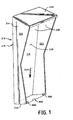
- FIG. 7 is a perspective view of an exemplary cartridge which is configured for use with the exemplary container of FIG. 3.
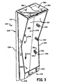
- FIG. 8 is a perspective view of another exemplary embodiment showing an exemplary cartridge as depicted in FIG. 7 placed in an exemplary housing as shown in FIG. 3.
- FIG. 9 is yet another embodiment of an exemplary housing.
- FIG. 10 is an exemplary cartridge which is intended to be inserted into the housing shown in FIG. 9.
- FIG. 11 is an enlarged cross-sectional view (not to scale) of the lower portion of the container and cartridge assembly shown in FIGS. 6 or 8.
- The present invention relates to a
container 210 for holdingpaper products 212 to be dispensed to a user. As shown in FIGS. 1 and 2,container 210 includes ahousing 214 defined byexterior walls 216, includingfirst wall 218,second wall 220, and athird wall 222.Exterior walls 216 define aninterior surface 230, within which is disposed aninterior area 228. Thehousing 214 further includes afirst end wall 240 and may also include asecond end wall 242.Paper products 212 are dispensed in a dispensingdirection 244.Housing 214 includes plurality ofprotrusions 250, includingcurved bumpers 252 havingridges 254 andrib members 258 disposed in astaging area 256. - Another feature which may be seen in FIGS. 1 and 2 is the fully open face of the dispensers which includes one or more cartridge retaining means 900 which may be affixed to the
end wall 240 and/orexterior walls - The cartridge retaining means 900 may be small blocks, chucks, stops, wires, braces, brackets, pins, clips or the like as well as combinations thereof. Alternatively and/or additionally, it is contemplated that other devices such as hooks, clamps or the like, adhesive materials, or interlocking or interacting container and cartridge geometries may be may be used as cartridge retaining means. The position of these means may be in the interior of the container and the illustration of the means at the exterior is not intended to be limiting.
- A
thumb notch 902 may be located in thefirst end wall 240 along the dispensingdirection 244. The thumb notch may be configured in any shape or size that is appropriate for the dimensions of the dispenser and the product to be dispensed. Desirably, the thumb notch will have dimensions that are compatible with the dimensions of any finger or thumb notches in any cartridges containing paper products used with the container. - The container shown in FIG 2 is generally similar to the one shown in FIG. 2. It can be seen that the housing depicted in FIG. 2 has a plurality of protrusions, including
curved bumpers 252 which may include ridges, andrib members 258 located in astaging area 256. - An optional
fourth wall 224 may be included in the container as shown in FIG. 3. Thefourth wall 224 may partially cover the front of the housing and may function as a cartridge containing means. Although thefourth wall 224 is shown intersecting or contacting thefirst end wall 240, thefourth wall 224 may be separated from the first end wall and appear as a band or strip or wall connecting thesecond wall 220 and thethird wall 222. Alternatively and/or additionally, the optionalfourth wall 224 may have a fixed portion and a hinged portion that may function as a door. If an optionalfourth wall 224 is used, a dispensingthroat 232 may be provided at the intersection of thefourth wall 224 and thefirst end wall 240. In such an embodiment,paper products 212 are dispensed in a dispensingdirection 244 through the dispensingthroat 232. As shown in FIG. 3, thefourth wall 224 may be quite small and with thefirst end wall 240 form a dispensingthroat 232 leaving a face of thecontainer 210 substantially open Further,housing 214 can also be constructed with double walls for security reasons. - The
housing 214 may include an attachment portion for attaching the housing to a substantially nonhorizontal surface such as vertical wall. As shown in FIG. 3, anattachment portion 246 may define holes through thefirst wall 218 of thehousing 214 for receiving attachment members (not shown) such as screws, bolts, nails, etc. for attaching the housing to a wall. Altemately, a mounting bracket could be formed on an exterior surface of the first wall for contacting and being supported by another bracket, screws, bolts, nails, etc. extending from a wall. Further, the housing could be secured to a wall via a glue, epoxy, etc., or any other type of adhesive. Also, it would be possible to locate theattachment portion 246 on any part of thehousing 214, such as thesecond wall 220, thethird wall 222, thefirst end wall 240, orsecond end wall 242, and to use combinations of mounting devices on several of the above-identified parts of the housing. Further, the housing could simply be positioned such thatfirst end wall 240 is lower than thesecond end wall 242, and so that thefirst end wall 240 and possibly thefirst wall 218 are supported in some way without fixing thehousing 214 to any particular structure. - Thus, the means for urging
paper products 212 in a dispensingdirection 244 may comprise any structure or orientation, or both, of thehousing 214 and/or wall it is mounted on that allowspaper products 212 to be urged in dispensing direction 44 by gravity. Other types of mechanisms for urgingpaper products 212 the dispensingdirection 244 such as, for example, spring loaded plates and the like are contemplated and may be especially useful if the container is mounted horizontally. For example, the container may project horizontally from a wall or may be placed on or mounted to a horizontal surface (e.g., on a countertop, table top or workbench). - In accordance with the invention, at least one protrusion, referred to generally as 250, extends from
interior surface 230 on at least one ofexterior walls 216 intointerior area 228 ofhousing 214. Desirably, as shown in FIG. 3,second wall 220 andthird wall 222 includeprotrusions 250 extending intointerior area 228.Protrusions 250 preferably comprisecurved bumpers 252, which may include a plurality ofridges 254 extending across the curved bumpers perpendicular to dispensingdirection 244. -
Bumpers 252 extend intointerior area 228 to contactpaper products 212 and thereby oppose the means for urgingpaper products 212 in dispensingdirection 244. By extending intointerior area 228 to contactpaper products 212,bumpers 252 impede the movement ofpaper products 212 in the dispensingdirection 224, but do not prohibit such movement.Ridges 254 allownumerous paper products 212 to be contacted by an Individual bumper and allow for a smoother movement of paper products throughhousing 214. In embodiments where the means for urgingpaper products 212 In dispensingdirection 244indudes mounting housing 214 so that gravity causes such movement,protrusions 250 also supportpaper products 212 against the force of gravity.Protrusions 250 therefore reduce the gravitational force of the bottom of thepaper products 212, thereby making it easier for a user to remove Individual paper products from the container. - Generally speaking, the exterior curve of bumper may be defined by a radius of from about 2,858 to 4,445 cm (1.125 to 1.750 in.). The bumper may have a chordal length of from about 4,128 to 4,763 cm (1.625 to 1.875 in.).
Individual ridges 254 may each have a radius of from about 0,318 to 0,635 cm (0.125 to 0.250 in.), and their centers may each be spaced about 0,635 cm (0.250 in.) from the center ofbumper 252. While the disclosed bumper shape is the a desired shape, other shapes could be used. - In accordance with the invention,
protrusions 250 onsecond wall 220 are desirably staggered fromprotrusions 250 onthird wall 222 relative to dispensingdirection 244. Such staggering provides a smooth movement ofpaper products 212 along dispensingdirection 244.Paper products 212, being supported alternately on one side or the other by the staggeredprotrusions 250, "walk" downhousing 214 in dispensingdirection 244.Staggering protrusions 250 in dispensingdirection 244 is important in embodiments wherepaper products 212 are moved in dispensingdirection 244 due to the mounting or orientation ofhousing 214 by gravity. For example, ifprotrusions 250 were spaced opposite from each other onsecond wall 220 andthird wall 222,paper products 212 might be entirely prevented from moving in dispensing direction and thus sit on top of a pair ofprotrusions 250. Also,paper products 212 might unevenly move In spurts past a pair ofnon-staggered protrusions 250 which could lead to misaligning of paper products and ultimately jamming of paper products withinhousing 214. Thus, staggering ofprotrusions 250 allows an orderly walking ofpaper products 212 along housing 124 in dispensingdirection 244 where first one side of the paper products, and then the other, moves more steadily downward. - The
container 210 includes a second group ofprotrusions 250 extending fromfirst wall 218 intointerior area 228 to contactpaper products 212. The second group ofprotrusions 250 is preferably disposed In astaging area 256 near dispensing throat 32 for spacing, slowing, aligning and supportingpaper products 212 as they are moved in dispensingdirection 244. Preferably, the second group ofprotrusions 250 includesseveral rib members 258 extending parallel to dispensingdirection 244 as shown In FIG. 2. Rlbmembers 258 may have different dimensions to property support and guide thepaper products 212. For example,rib members 258 may have a sloping configuration and an optional radius of curvature. - Generally speaking, the
rib members 258 may have a height ranging from about 1,27 to about 5,08cm (0.5 to about 2 inches) at the location where it intersects with thefirst wall 218 and, in some embodiments, may even have an offset or height ranging from about 0,254 to about 1,27 cm (0.1 to about 0.5 inch) where therib member 258 is adjacent to or contacts thefirst end wall 240. - However, is should be understood that the dimensions of these rib members may be varied to accommodate a variety of factors including, but not limited to, the size of the paper product, basis weight of the paper product, composition/texture of the paper product, fold pattern of the paper product, height of the stack of paper products, force supplied by the means to urge the paper products to the dispensing throat, amount and dimensions of protrusions located on the second and third walls of the container as well as amount of other rib members positioned proximate the dispensing throat
- The
housing 214 may be made of injection-molded plastic such as polyethylene or nylon. However, other suitable materials, such as other plastics or metals, may be provided for any or all of the parts of thehousing 214.Curved bumpers 252 andrib members 258 are preferably formed integral withhousing 214. However, curvedbumpers 252 andrib members 258 may be formed separately fromhousing 214 and attached later. Also,curved bumpers 252 andrib members 258 may be made of different material fromhousing 214 if desired. For example,curved bumpers 252 and/orrib members 258 may be made of a more resilient material than the materials described above, such as an elastomer or rubber. - While
curved bumpers 252 have been described as disposed on second andthird walls curved bumpers 252 could be disposed on any pair of opposite walls of thehousing 214. Also, although rib member ormembers 258 have been described as disposed on thefirst wall 218, rib member ormembers 258 could be disposed on any wall or pair of opposite walls of housing. - Desirably, the
paper products 212 are interfolded or tab interfolded to provide metered feeding of individual napkins one at a time. However, the present invention does not require the use of interfolded paper products. - The
housing 214 may hold multiple clips of paper products 214 (if a cartridge is not used), and may extend from 30 to as much as 48 in. from end to end. Desirably,first wall 218 is angled between 0-5 degrees from the vertical to prevent paper products from falling out of thehousing 214 during refilling. - Referring now to FIG. 4, there is shown a
cartridge 262 which is adapted to be inserted into theinterior area 228 of thehousing 214 and which is further adapted for holding or containingpaper products 212 to be dispensed. As illustrated in FIG. 6, thecartridge 262 is sized to fit snugly within theinterior area 228 of thehousing 214. If desired, leaf springs 264 (see FIG. 3) may be provided attached to the inside of thesecond end 242 of thehousing 214 to hold thecartridge 262 in place. Any other suitable mechanism such as a tab or other interlock may be used to hold thecartridge 262 in thehousing 214 is within the scope of the invention. - Referring again to FIG. 4, the
cartridge 262 includes a plurality ofremovable portions 268, the removal of which createsopenings 270 through thecartridge 262.Removable portions 268 are disposed inoutside walls 272 ofcartridge 262 so that, onceremovable portions 268 are removed,openings 270 encompass and receiveprotrusions 250 that may extend from theinterior surface 230 of thehousing 214. Thus, upon removal ofremovable portions 268 and placement ofcartridge 262 inhousing 214,curved bumpers 252 andrib members 258 contact thepaper products 212 within cartridge. - FIG. 5 is a perspective view of another
exemplary cartridge 262. Generally speaking, the cartridge includes a cartridge body having cartridge walls and may further include removable sections defined in the cartridge body generally as described above. Since the container embodiments of FIGS. 1 and 2 described above may have an open face rather than a dispensing throat, acartridge front wall 272a (illustrated in FIGS. 4 and 5) is intended to be positioned in the open face of the container and includes a slit, slot, orifice orchannel 950 that can serve to control access to thepaper products 212 held within. Desirably, the slot is defined by thecartridge front wall 272a and thebottom wall 272b of the cartridge. However, it is contemplated that other locations may be used. - The slit is desirably sized so that it has a horizontal dimension " H " that is about the same as or slightly greater than the width of the paper products within the cartridge and a vertical dimension "V" that is large enough to permit the passage of a limited number of paper products. For example, if the paper products are in the form of folded paper napkins, the vertical dimension " V " of the slit may be sized so that a limited number of folded paper napkins may extracted. This could be achieved by making the vertical dimension " V " some multiple of the thickness of an individual folded paper napkin (e.g., desirably greater than about 2 and less than about 10 thicknesses, even more desirably greater than about 2 and less than about 6 thicknesses).
- The paper product may be accessed by a
thumb slot 952 and/or afinger slot 954. Desirably, these slots are located on the front and bottom faces of the cartridge and may be centered with respect to the dimensions of the cartridge or the dimensions of the slot. - The cartridge may define at least one
additional slot 282 through one of the cartridge walls, the slot being visible from outside the housing when the cartridge is in the interior area of the housing, an amount of paper products disposed within the cartridge being determinable by visually inspecting the amount of paper products through the slot. -
Cartridge 262 may also include anotherremovable portion 278 disposed atend 280 ofcartridge 262.Removable portion 278 may be removed to receive a spring-loaded plate ifcartridge 262 is to be used in a container with a spring-loaded plate or other means for urging the paper products in the dispensing direction. - As shown in FIG. 7, a
removable portion 274 may be provided atend 276 ofcartridge 262 for use in containers of the type shown in FIG. 3 so thatpaper products 212 can be supported and aligned byrib member 258 for dispensing through dispensingthroat 232. Alternately, end 276 ofcartridge 262 may be formed such that a plurality of smaller removable portions may be provided corresponding torib members 258. It is also contemplated that a different smaller removable portion may be provided corresponding to the dispensingthroat 232. If a separate removable portion corresponding to the dispensingthroat 232 is provided, it is contemplated that it may be used with or without other removable portions corresponding to rib members and/or any other protrusions. - Generally speaking,
removable portions cartridge 262 or removed during installation ofcartridge 262 inhousing 214. If these removable portions are to be removed as part of the manufacturing process,cartridge 262 should be shipped to the user wrapped, for example in a polyethylene bag, to prevent contamination and/or to preserve the sterility of the paper products in the cartridge. If the removable portions are to be removed as part of the installation process, the edges of the removable portions should be weakened, scored, etc. for easy removal. It is desirable thatremovable portion 274 should not be removed as part of the manufacturing process to ensure thatpaper products 212 remain properly loaded incartridge 262. - Optional
removable portions 268 may be placed on front wall 272 (and/or a back wall which is not shown) ofcartridge 262.Removable portions 268 may be used if optional protrusions 258 (i.e., rib members) are used on thefirst wall 218 of the housing 214 (see, for example, FIG. 2 - Preferably,
cartridge 262 includes at least oneslot 282 extending through one of thecartridge walls 272.Slot 282 is visible from outside ofhousing 214 whencartridge 262 is mounted ininterior area 228. A user can visually determine the amount ofpaper products 212 remaining withincartridge 262 by inspecting the amount of paper products visible throughslot 282. As shown in FIG. 7, two slots may be provided to provide a greater range of visual inspection. Any number or arrangement of slots is possible within the scope of the invention. -
Cartridge 262 is preferably made of heavy paper or cardboard, but may be made of any other suitable material within the scope of the invention. - Referring again to FIG. 6, there is shown a perspective view of an exemplary cartridge as depicted in FIG. 4 placed in an exemplary housing as shown in FIGS. 1 or 2. A dispensing direction " D " is identified as generally perpendicular to the housing and cartridge assembly. If the paper product is, for example, an interfolded paper napkin or tissue, a leading flap or
tail 960 would extend out of theslot 950 and be available for a user to grasp. - FIG. 8 is a perspective view of an
exemplary cartridge 262 which may be of the type illustrated in FIGS. 4, 5 or 7 placed into an exemplary housing which may be of the type shown in FIG. 3 that has a dispensingthroat 232. A dispensing direction " D " is identified as generally perpendicular to the housing and cartridge assembly. If the paper product is, for example, an interfolded paper napkin or tissue, a leading flap ortail 960 would extend out of the dispensingthroat 232 and be available for a user to grasp. - The dispensing
throat 232 is desirably sized so that it has a horizontal dimension "H" that is about the same as or slightly greater than the width of the paper products within the cartridge and a vertical dimension "V" that is large enough to permit the passage of a limited number of paper products. Of course, thecartridge 262 will need to be configured to cooperate with the dispensing throat. Generally speaking, if the paper products are in the form of folded paper napkins, the vertical dimension "V" of the dispensing throat may be sized so that a limited number of folded paper napkins may extracted. This could be achieved by making the vertical dimension "V" some multiple of the thickness of an individual folded paper napkin (e.g., desirably greater than about 2 and less than about 10 thicknesses, even more desirably greater than about 2 and less than about 6 thicknesses). - The paper product may be accessed by a thumb slot and/or a finger slot. Desirably, these slots are located on the
fourth wall 224 and thefirst end wall 240 and may be centered with respect to the dimensions of the housing or the dimensions of the dispensingthroat 232. - FIG. 9 is yet another embodiment of an exemplary housing. This embodiment differs from the embodiments shown in FIGS. 1 and 2 in that the
first end wall 240 of FIGS. 1 and 27 generally slopes away from the front or open face of the housing. In contrast, thefirst end wall 240 of FIG. 9 slopes into or opens up to the front or open face of the housing. - FIG. 10 is an exemplary cartridge which is intended to be inserted into the housing shown in FIG. 9. The
cartridge front wall 272a and thebottom wall 272b are configured to fit snugly in the housing. - FIG. 11 is an enlarged cross-sectional view (not to scale) of the lower portion of the container and cartridge assembly shown in FIG. 6. The
cartridge front wall 272a, acartridge bottom wall 272b and a cartridgeback wall 272c and a stack ofinterfolded paper product 212 is shown. As can been seen in the enlarged and expanded view, theslot 950 has a vertical dimension " V " which is generally some multiple of the thickness of a single layer or ply or fold of thepaper product 212. A dispensing direction " D " is identified as generally perpendicular to the housing and cartridge assembly. If the paper product is, for example, an interfolded paper napkin or tissue, a leading flap ortail 960 can been seen extending out of theslot 950 for a user to grasp. Pulling the leadingflap 960 will result in one-at-a-time dispensing of the product. - It should be understood that FIG. 11 may also generally represent an enlarged cross-sectional view (not to scale) of the lower portion of the container and cartridge assembly shown in FIG. 8. The
cartridge front wall 272a may be read as corresponding to thefourth wall 224, thebottom wall 272b corresponding to thefirst end wall 240, theback wall 272c corresponding to thefirst wall 218, theslot 950 corresponding to the dispensingthroat 232, and the finger and thumb slots in the cartridge corresponding to finger and thumb slots in thefourth wall 224 and thefirst end wall 240. Of course, the cartridge may be configured as shown in FIGS 4, 5 and/or 7 to cooperate with the dispensing throat. Thus, the following description applies to embodiments of the invention having a generally open face (i.e., lacking a dispensing throat in the housing) as well as embodiments with a dispensing throat. - Gripping the interfolded product between
lower grip point 1000 and a firstupper grip point 1002 engages two of the interfolded paper products (e.g., napkins, tissues, wipes, etc.) for dispensing. One of which has avisible tail 960 extending from the slot 950 (or dispensing throat 232) and the other still located inside the cartridge but accessible through thefinger slot 954. Pulling the product engaged atgrip points grip areas - Pulling the product engaged at
grip points grip areas - Pulling the product engaged at
grip points grip areas - If a non-interfolded product is used in the cartridge, the dispensing direction " D " remains the same. However, there will be no leading flap as in the interfolded format. Generally speaking, the number of products dispensed will be the same as the number of forward folds gripped unless the product is double or triple folded.
- Thus, it can be seen how the container and cartridge may be used to dispenser a controlled amount of paper products.
- It is intended that the present invention include such modifications and variations as come within the scope of the appended claims.
Claims (20)
- A container (210) for dispensing a controlled amount of paper products (212) from a cartridge (262) holding a plurality of paper products (212), the container (210) comprising
a housing (214) including
a first end wall (240) and
a plurality of exterior walls (216)
defining an interior surface (230) and an interior area (228) within the interior surface (230) for receiving a cartridge (262) holding a plurality of paper products (212),
a first (218), second (220) and third (222) of the exterior walls intersecting the first end wall (240), the second and third of the exterior walls being on opposite sides of the first exterior wall (218), forming a portion of the interior surface (230), and defining an open face of the container,
a means for urging paper products (212) within the interior area (228) toward the first end wall (240) in a dispensing direction (244),
cartridge retaining means (900), and
a cartridge (262) for insertion into the interior area (228) of the housing (214) for containing the plurality of paper products (212), the cartridge (262) comprising
a cartridge body having cartridge walls (272), and the cartridge including
a cartridge wall (272a) for positioning in the open face of the container (210), the cartridge wall (272a) including
a slit for controlling access to the paper products (212) held within. - The container of claim 1, wherein the cartridge retaining means (900) is selected from blocks, chucks, stops, wires, braces, brackets, bars, pins, clips and combinations thereof.
- The container of claim 2, wherein the cartridge retaining means (900) are configured on the first end wall (240) or opposing second (220) and third (222) exterior walls.
- The container of claim 2, further comprising a finger slot in the first end wall (240).
- The container of claim 1, the housing further comprising a staging area proximate the first end wall (240) for spacing and slowing the paper products (212).
- The container of claim 1, further comprising protrusions extending from the portion of the interior surface on the exterior walls into the interior area for contacting the paper products (212) to oppose the means for urging.
- The container of claim 1, wherein the cartridge (262) is configured so the slit is defined by a front wall and a bottom wall of the cartridge.
- The container of claim 1, wherein the cartridge (262) is configured so the slit is sized to have a horizontal dimension about the same as or slightly greater than the width of the paper products within the cartridge and a vertical dimension that is large enough to permit the passage of a limited number of paper products.
- The container of claim 8, wherein the cartridge (262) is configured so the vertical dimension of the slit is between about 2 and about 10 times the thickness of an individual folded paper product.
- The container of claim 1, wherein the cartridge (262) is configured so the paper products may be accessed by a thumb slot and a finger slot.
- The container of claim 1, wherein the cartridge (262) includes removable portions, removal of the removable portions creating openings in the cartridge.
- The container of claim 11, wherein at least one of the openings in the cartridge (262) is disposed adjacent at least one of the protrusions so that the protrusion extends through the opening to contact the plurality of paper products (212).
- The container of claim 1, wherein a fourth exterior wall (224) that cooperates with the first end wall (240) to define a dispensing throat (232) for controlling access to paper products (212) held within the container (210) serves as the cartridge retaining means (900).
- The container of claim 13, wherein the dispensing throat is sized to have a horizontal dimension about the same as or slightly greater than the width of the paper products within the container and a vertical dimension that is large enough to permit the passage of a limited number of paper products.
- The container of claim 14, wherein the vertical dimension of the dispensing throat is between about 2 and about 10 times the thickness of an individual folded paper product.
- A container (210) for dispensing a controlled amount of paper products (212), the container (210) comprising:a housing (214) including
a first end wall (240) and
a plurality of exterior walls (216)
defining an interior surface (230) and an interior area (228) within the interior surface (230) for receiving a cartridge (262) holding the plurality of paper products (212),
a first (218), second (220) and third (222) of the exterior walls intersecting the first end wall (240), the second and third of the exterior walls being on opposite sides of the first exterior wall (218), forming a portion of the interior surface (230), and defining an open face of the container (210),
a means for urging paper products (212) within the interior area (228) toward the first end wall (240) in a dispensing direction (244), and
a fourth exterior wall (224) that cooperates with the first end wall (240) to define a dispensing throat (232) for controlling access to paper products (212) held within the container (210), anda cartridge (262) being insertable into the interior area (228) of the container (210), comprising
a cartridge body including
cartridge walls (272), wherein at least one cartridge wall (272a) is adapted for positioning in the open face of the container (210) and further adapted to define a slit (950) for controlling access to the paper products (212) held within, and wherein the slit (950) corresponds to the dispensing throat (232). - The container of claim 16, wherein the cartridge (262) is configured so the slit is defined by a front wall (272a) and a bottom wall (272b) of the cartridge.
- The container of claim 16, wherein the cartridge (262) is configured so the slit is sized to have a horizontal dimension about the same as or slightly greater than the width of the paper products (212) within the cartridge and a vertical dimension that is large enough to permit the passage of a limited number of paper products (212).
- The container of claim 18, wherein the cartridge (262) is configured so the vertical dimension of the slit is between about 2 and about 10 times the thickness of an individual folded paper product (212).
- The container of claim 17, wherein the cartridge (262) is configured so the paper products (212) may be accessed by a thumb slot and a finger slot.
Applications Claiming Priority (3)
| Application Number | Priority Date | Filing Date | Title |
|---|---|---|---|
| US20695698A | 1998-12-08 | 1998-12-08 | |
| US206956 | 1998-12-08 | ||
| PCT/US1999/029137 WO2000033713A1 (en) | 1998-12-08 | 1999-12-08 | Container and cartridge for dispensing controlled amounts of paper products |
Publications (2)
| Publication Number | Publication Date |
|---|---|
| EP1137357A1 EP1137357A1 (en) | 2001-10-04 |
| EP1137357B1 true EP1137357B1 (en) | 2006-06-07 |
Family
ID=22768654
Family Applications (1)
| Application Number | Title | Priority Date | Filing Date |
|---|---|---|---|
| EP99964173A Expired - Lifetime EP1137357B1 (en) | 1998-12-08 | 1999-12-08 | Container comprising a cartridge for dispensing controlled amounts of paper products |
Country Status (14)
| Country | Link |
|---|---|
| US (1) | US6830151B2 (en) |
| EP (1) | EP1137357B1 (en) |
| JP (1) | JP2002531337A (en) |
| AR (1) | AR021585A1 (en) |
| AT (1) | ATE328520T1 (en) |
| AU (1) | AU772307B2 (en) |
| CA (1) | CA2352857A1 (en) |
| CO (1) | CO5021138A1 (en) |
| DE (1) | DE69931808T2 (en) |
| ES (1) | ES2263293T3 (en) |
| HK (1) | HK1040599A1 (en) |
| PE (1) | PE20001075A1 (en) |
| TW (1) | TW431880B (en) |
| WO (1) | WO2000033713A1 (en) |
Families Citing this family (25)
| Publication number | Priority date | Publication date | Assignee | Title |
|---|---|---|---|---|
| DE50014784D1 (en) * | 2000-08-25 | 2007-12-27 | Hts Int Trading Ag | Dispenser for cleaning tissue |
| EP1232716A1 (en) * | 2001-02-15 | 2002-08-21 | The Procter & Gamble Company | Container for dispensing wipes |
| US6585130B2 (en) | 2001-07-19 | 2003-07-01 | Unilever Home & Personal Care, Usa Division Of Conopco, Inc. | Wipe dispenser |
| WO2003030112A2 (en) * | 2001-10-01 | 2003-04-10 | Frank Runnels | Apparatus for dispensing flat items |
| US6634037B2 (en) | 2001-12-17 | 2003-10-21 | Unilever Home And Personal Care, Usa Division Of Conopco, Inc. | Personal cleansing system |
| ES2385326T3 (en) * | 2003-01-10 | 2012-07-23 | Georgia-Pacific France | Blade distributor with braking means |
| US7093737B2 (en) | 2003-04-16 | 2006-08-22 | Kimberly-Clark Worldwide, Inc. | Container and cartridge for dispensing paper products |
| US7124911B2 (en) | 2003-04-16 | 2006-10-24 | Kimberly-Clark Worldwide, Inc. | Container and cartridge for dispensing paper products |
| US7048143B2 (en) | 2003-04-16 | 2006-05-23 | Kimberly-Clark Worldwide, Inc. | Container and cartridge for dispensing paper products |
| US8328046B2 (en) * | 2003-09-12 | 2012-12-11 | Sca Tissue North America Llc | Dispenser for folded absorbent sheet products |
| DE102004040463A1 (en) * | 2004-06-01 | 2005-12-29 | Gerold Dr. Weinmann | Device for disposing of a hygiene article |
| GB0419261D0 (en) * | 2004-08-27 | 2004-09-29 | Mach Shop Special Effects Ltd | Confetti and confetti-like discharge |
| US20060163268A1 (en) * | 2005-01-21 | 2006-07-27 | Kuehneman Bret A | Napkin dispenser with dispensing control frame |
| US7766187B2 (en) * | 2006-08-31 | 2010-08-03 | James A. Schaefers | Napkin dispenser |
| DE202010004469U1 (en) * | 2010-04-01 | 2011-08-11 | Ophardt Hygiene-Technik Gmbh + Co. Kg | Dispensers for solid consumer goods and dispensers for storing and dispensing fluid or pasty substances |
| WO2012027346A2 (en) * | 2010-08-23 | 2012-03-01 | Georgia-Pacific Consumer Products Lp | Sheet product dispensing unit and a cartridge therefore |
| GB201216119D0 (en) * | 2012-09-10 | 2012-10-24 | Altevo Ltd | Stacking of gloves |
| EP3094227A4 (en) * | 2014-01-13 | 2017-08-09 | Georgia-Pacific Consumer Products LP | Sheet product dispensers and related methods for automatically loading a roll of sheet product in a dispenser |
| US20160318696A1 (en) * | 2015-05-01 | 2016-11-03 | New Pig Corporation | Spill kit dispensing systems |
| USD806573S1 (en) * | 2015-08-05 | 2018-01-02 | Ken Sobel | Dispenser for tissues and hand-pulled paper products |
| US11412900B2 (en) | 2016-04-11 | 2022-08-16 | Gpcp Ip Holdings Llc | Sheet product dispenser with motor operation sensing |
| US11395566B2 (en) | 2016-04-11 | 2022-07-26 | Gpcp Ip Holdings Llc | Sheet product dispenser |
| USD807035S1 (en) * | 2016-07-19 | 2018-01-09 | Jeff J. Beller | Insulated beverage holder dispenser |
| US11116365B2 (en) | 2019-12-18 | 2021-09-14 | Essity Hygiene And Health Aktiebolag | Horizontally oriented paper product dispenser and related methods |
| US10980377B1 (en) | 2019-12-18 | 2021-04-20 | Essity Hygiene And Health Aktiebolag | Apparatus and methods for paper dispensing |
Family Cites Families (93)
| Publication number | Priority date | Publication date | Assignee | Title |
|---|---|---|---|---|
| US371473A (en) | 1887-10-11 | Chaeles s | ||
| FR336986A (en) | 1903-11-07 | 1904-03-22 | Arthur Eugene Sexton | Paper holder |
| US813594A (en) | 1903-12-26 | 1906-02-27 | Arthur E Sexton | Paper-holder. |
| US1170380A (en) | 1914-06-02 | 1916-02-01 | Courtney P Winter | Paper-dispensing cabinet. |
| US1236055A (en) | 1916-03-07 | 1917-08-07 | Max M Cohn | Interleaved paper container and dispenser. |
| US1605231A (en) | 1922-08-24 | 1926-11-02 | Frank H Hoberg | Supply cabinet for interfolded sheets |
| US1579429A (en) | 1923-12-11 | 1926-04-06 | R C Pell Jr | Starting device for packed folded paper |
| US1709214A (en) | 1926-03-04 | 1929-04-16 | Griffith Hope Company | Paper cabinet |
| US1665057A (en) | 1926-12-09 | 1928-04-03 | Genest Lucien | Tickets holder |
| US1974926A (en) | 1932-11-25 | 1934-09-25 | Harry V Marsh | Counter dispensing device |
| US2033582A (en) | 1933-02-04 | 1936-03-10 | Materno Arthur | Dispensing container for toilet paper |
| GB423276A (en) * | 1934-01-24 | 1935-01-29 | Jeyes Sanitary Compounds Compa | Improvements in or relating to cartons for interleaved paper, cloth and the like |
| US1989381A (en) | 1934-03-07 | 1935-01-29 | Nat Paper Products Company | Paper dispensing cabinet |
| US2143614A (en) | 1938-07-19 | 1939-01-10 | Us Paper Mills Inc | Shipping and dispensing package |
| US2323395A (en) | 1939-04-12 | 1943-07-06 | Int Cellucotton Products | Dispensing carton |
| US2195437A (en) | 1939-07-24 | 1940-04-02 | Crown Zellerbach Corp | Interfolded tissue dispenser |
| US2730267A (en) | 1953-01-26 | 1956-01-10 | Marcalus Nicholas | Dispensing |
| US2816376A (en) | 1954-09-01 | 1957-12-17 | Kenneth R Hirvonen | Holder for photoprints and the like |
| US2858045A (en) | 1955-12-06 | 1958-10-28 | Joseph P Loeb | Tissue dispenser |
| US2858016A (en) | 1957-09-05 | 1958-10-28 | Wilson Jones Co | Memorandum paper tray |
| US3028047A (en) | 1958-03-11 | 1962-04-03 | Crown Zellerbach Corp | Dispenser receptacle for folded sheets |
| US3164298A (en) | 1961-05-26 | 1965-01-05 | Dow Chemical Co | Dispensing package |
| US3161336A (en) | 1962-07-25 | 1964-12-15 | Kimberly Clark Co | Cellulosic product |
| US3203586A (en) | 1963-02-07 | 1965-08-31 | Fort Howard Paper Co | Napkin dispensers having means for facilitating withdrawal |
| US3258114A (en) | 1964-04-03 | 1966-06-28 | Elmore L King | Packaging and dispensing container |
| US3272385A (en) | 1965-04-12 | 1966-09-13 | Int Paper Canada | Dispenser box |
| DE1289274B (en) * | 1965-07-17 | 1969-02-13 | Waldhof Zellstoff Fab | Storage container for material web sections |
| US3332594A (en) | 1965-10-22 | 1967-07-25 | Olin Mathieson | Container for shotgun shells |
| US3343716A (en) | 1966-03-22 | 1967-09-26 | Peebles David Meade | Dispensers for facial tissues and the like |
| US3349959A (en) | 1966-09-14 | 1967-10-31 | Int Paper Canada | Box for dispensing stacked sheets |
| FR1537127A (en) | 1967-07-12 | 1968-08-23 | Cie De Kaysersberg | Improvements to paper distributors |
| US3724716A (en) | 1971-02-24 | 1973-04-03 | W Baraconi | Bag dispenser |
| US3754681A (en) | 1971-03-11 | 1973-08-28 | Alwin Mfg Co Inc | Universal towel dispenser |
| US3747802A (en) | 1971-05-21 | 1973-07-24 | Alpha Designs Inc | Portable dispensing containers |
| US3843085A (en) | 1973-09-14 | 1974-10-22 | M Castro | Supporting structure for disposable tissue dispenser |
| US4004691A (en) * | 1975-12-22 | 1977-01-25 | Arbrook, Inc. | Glove package box with interchangeable identification |
| FR2362610A1 (en) | 1976-08-30 | 1978-03-24 | Ragot Claude | Single paper towel dispenser - has slot in box side orthogonal to sheet fold lines and weight on top of stack |
| AU83321S (en) | 1981-02-13 | 1981-11-19 | Bowater Scott Ltd | dispenser |
| US4411374A (en) | 1981-08-03 | 1983-10-25 | Kimberly-Clark Corporation | Tissue dispenser system, plastic overwrap package therefor |
| US4469243A (en) | 1982-03-31 | 1984-09-04 | Kimberly-Clark Corporation | Combination carton and shipping package, dispensing system therefor |
| US4491242A (en) | 1982-12-02 | 1985-01-01 | Trinidad Maria A | Napkin holder |
| US4679703A (en) | 1984-03-02 | 1987-07-14 | Georgia-Pacific Corporation | Device for preventing napkins from bunching at the dispensing opening in a paper napkin dispenser |
| US4566607A (en) | 1984-05-24 | 1986-01-28 | Smith David L | Bag dispenser |
| US4678099A (en) | 1985-02-19 | 1987-07-07 | Sumio Matsui | Container for storing stack of thin and soft sheet materials |
| US4623074A (en) | 1985-02-25 | 1986-11-18 | The Procter & Gamble Company | Dual dispensing mode carton and concomitant package |
| US4706844A (en) | 1985-07-24 | 1987-11-17 | San Jamar, Inc. | Napkin dispenser |
| USD302949S (en) | 1986-05-09 | 1989-08-22 | Eisendrath Stuart J | Diaper dispenser |
| US4805800A (en) | 1986-09-04 | 1989-02-21 | Minigrip, Inc. | Dispenser for plastic bags |
| US4938382A (en) | 1987-07-30 | 1990-07-03 | Scott Paper Company | Dispensing cabinet for paper sheets |
| US4838454A (en) * | 1987-11-02 | 1989-06-13 | Traex Corporation | Napkin dispenser |
| US4848575A (en) | 1988-03-02 | 1989-07-18 | Eluci Company Inc. | Resealable dispenser-container for wet tissues |
| US5002200A (en) | 1988-09-22 | 1991-03-26 | Hunt William G | Method and apparatus for storing used plastic bags for refuse |
| GB2225312A (en) * | 1988-11-28 | 1990-05-30 | Kimberly Clark Ltd | Dispensers |
| US5065895A (en) | 1989-08-02 | 1991-11-19 | Georgia Pacific Corporation | Variable support for fan-folded paper dispenser |
| GB2235431A (en) * | 1989-09-01 | 1991-03-06 | Kimberly Clark Ltd | Sheet dispensers |
| JPH03187873A (en) | 1989-12-07 | 1991-08-15 | Shigeru Hirano | Auxiliary plate for taking out facial tissue |
| US5020670A (en) * | 1990-08-10 | 1991-06-04 | Peter H. Bedford | Shipping carton and dipsenser for sponge articles |
| US5143252A (en) | 1990-11-05 | 1992-09-01 | Zhimin Shi | Portable package and system for storing and dispensing photographic film cartridges |
| US5102007A (en) | 1991-03-12 | 1992-04-07 | James River Ii, Inc. | Dispenser for folded sheet products |
| US5090592A (en) | 1991-03-12 | 1992-02-25 | James River Ii, Inc. | Nose piece for folded sheet product dispenser |
| US5100020A (en) | 1991-03-12 | 1992-03-31 | James River Ii, Inc. | Folded sheet product dispenser system |
| US5310057A (en) | 1991-12-10 | 1994-05-10 | Lever Brothers Company, Division Of Conopco, Inc. | Fabric softener sheet dispenser |
| GB9202822D0 (en) * | 1992-02-11 | 1992-03-25 | Wyant And Company Limited | Dispenser for folded paper towels |
| USD347344S (en) | 1992-11-25 | 1994-05-31 | Schumaker Donald D | Dispenser for stacked articles |
| US5346064A (en) | 1993-02-25 | 1994-09-13 | James River Paper Company, Inc. | Center-pull roll product dispenser package |
| US5622281A (en) | 1993-06-02 | 1997-04-22 | Bfa Manufacturing Limited | Dispenser for folded sheets and bulk packets |
| DE4323473A1 (en) | 1993-07-14 | 1995-01-19 | Drl Hygiene Systeme Gmbh | Insert dispenser for hygiene articles or the like |
| US5332118A (en) | 1993-08-17 | 1994-07-26 | The Procter & Gamble Company | Pop-up towel dispensing system |
| US5356032A (en) | 1994-02-01 | 1994-10-18 | Encore Paper Company | Folded sheet product and dispenser therefor |
| US5462197A (en) | 1994-05-11 | 1995-10-31 | Pound; John D. | Towelette dispensing device for cleaning a toilet seat |
| US5460322A (en) | 1994-10-17 | 1995-10-24 | The Tranzonic Companies | Multi-purpose container |
| US5520308A (en) | 1994-11-21 | 1996-05-28 | The Procter & Gamble Company | Sequential dispensing of tissues and dispenser therefor |
| USD366583S (en) | 1995-02-27 | 1996-01-30 | Scaife Melvin C | Disposable diaper dispenser |
| US5565258A (en) | 1995-03-02 | 1996-10-15 | Kimberly-Clark Corporation | Folded absorbent paper product and method |
| US5590813A (en) | 1995-05-22 | 1997-01-07 | Abramczyk; Robert J. | Dispenser |
| US5642836A (en) | 1995-09-05 | 1997-07-01 | Merriweather, Jr.; Frank | Single piece towel dispenser |
| AU6952796A (en) | 1995-09-14 | 1997-04-01 | Kimberly-Clark Tissue Company | Improved paper towel dispensing mechanism for public washrooms |
| BR9610712A (en) | 1995-09-26 | 1999-07-13 | Kimberly Clark Co | Vandalo resistant bathroom dispensers |
| US5632409A (en) * | 1995-10-20 | 1997-05-27 | Raghunanan; Cheryl J. | Plastic bag holder |
| DE29519931U1 (en) | 1995-12-15 | 1996-02-29 | Procter & Gamble | Sales box to hold a variety of individual items |
| US5690230A (en) | 1996-04-02 | 1997-11-25 | Deroyal Industries, Inc. | Dispensing container for small flat items |
| US5931339A (en) | 1996-06-05 | 1999-08-03 | Georgia-Pacific Corporation | Process and apparatus for dispensing paper towels |
| FR2750958B1 (en) | 1996-07-12 | 1998-11-20 | Jamont N V | PAPER DISPENSER COMPRISING A REMOVABLE CASSETTE |
| US6378726B1 (en) | 1996-11-22 | 2002-04-30 | Kimberly Clark Worldwide, Inc. | Interfolded napkin dispensing system |
| US6286713B1 (en) | 1997-03-13 | 2001-09-11 | Kimberly-Clark Worldwide, Inc. | Dispensing system for individual folded webs |
| US5855302A (en) | 1996-12-18 | 1999-01-05 | Georgia-Pacific Corporation | Liquid dispensing cap valve assembly with pedestal mounted resilient valve seal element |
| US5836478A (en) | 1997-02-28 | 1998-11-17 | Atico International Usa, Inc. | Battery dispenser |
| US5950863A (en) | 1997-08-05 | 1999-09-14 | Perrin Manufacturing | Sheet dispenser insert |
| US6419113B1 (en) * | 1997-12-16 | 2002-07-16 | Kimberly-Clark Worldwide, Inc. | Cartridge for dispensing paper products |
| US6241118B1 (en) * | 1997-12-16 | 2001-06-05 | Kimberly-Clark Worldwide, Inc. | Container and cartridge for dispensing paper products |
| TW595456U (en) | 1997-12-16 | 2004-06-21 | Kimberly Clark Co | Container and cartridge for dispensing |
| USD414085S (en) | 1998-08-07 | 1999-09-21 | Angela Liat Deaver Campbell | Napkin holder |
| US6415949B1 (en) * | 2000-05-24 | 2002-07-09 | Kimberly-Clark Worldwide, Inc. | Container and cartridge for dispensing controlled amounts of paper products |
-
1999
- 1999-12-06 CO CO99076535A patent/CO5021138A1/en unknown
- 1999-12-07 PE PE1999001216A patent/PE20001075A1/en not_active Application Discontinuation
- 1999-12-07 AR ARP990106250A patent/AR021585A1/en not_active Application Discontinuation
- 1999-12-08 WO PCT/US1999/029137 patent/WO2000033713A1/en active IP Right Grant
- 1999-12-08 CA CA002352857A patent/CA2352857A1/en not_active Abandoned
- 1999-12-08 ES ES99964173T patent/ES2263293T3/en not_active Expired - Lifetime
- 1999-12-08 AU AU20470/00A patent/AU772307B2/en not_active Ceased
- 1999-12-08 DE DE69931808T patent/DE69931808T2/en not_active Expired - Fee Related
- 1999-12-08 EP EP99964173A patent/EP1137357B1/en not_active Expired - Lifetime
- 1999-12-08 AT AT99964173T patent/ATE328520T1/en not_active IP Right Cessation
- 1999-12-08 JP JP2000586213A patent/JP2002531337A/en not_active Abandoned
- 1999-12-31 TW TW088121301A patent/TW431880B/en not_active IP Right Cessation
-
2002
- 2002-04-04 HK HK02102556.0A patent/HK1040599A1/en unknown
- 2002-07-26 US US10/205,880 patent/US6830151B2/en not_active Expired - Fee Related
Also Published As
| Publication number | Publication date |
|---|---|
| EP1137357A1 (en) | 2001-10-04 |
| US6830151B2 (en) | 2004-12-14 |
| JP2002531337A (en) | 2002-09-24 |
| WO2000033713A1 (en) | 2000-06-15 |
| ATE328520T1 (en) | 2006-06-15 |
| HK1040599A1 (en) | 2002-06-21 |
| AU772307B2 (en) | 2004-04-22 |
| US20020179630A1 (en) | 2002-12-05 |
| CA2352857A1 (en) | 2000-06-15 |
| DE69931808T2 (en) | 2007-07-12 |
| TW431880B (en) | 2001-05-01 |
| DE69931808D1 (en) | 2006-07-20 |
| AU2047000A (en) | 2000-06-26 |
| AR021585A1 (en) | 2002-07-24 |
| ES2263293T3 (en) | 2006-12-01 |
| CO5021138A1 (en) | 2001-03-27 |
| PE20001075A1 (en) | 2000-10-18 |
Similar Documents
| Publication | Publication Date | Title |
|---|---|---|
| EP1137357B1 (en) | Container comprising a cartridge for dispensing controlled amounts of paper products | |
| US6422416B1 (en) | Cartridge for dispensing paper products | |
| EP1289399B1 (en) | Cartridge for dispensing controlled amounts of paper products | |
| US7093737B2 (en) | Container and cartridge for dispensing paper products | |
| US7048143B2 (en) | Container and cartridge for dispensing paper products | |
| AU2001259856A1 (en) | Container and cartridge for dispensing controlled amounts of paper products | |
| EP1039826B1 (en) | Container and cartridge for dispensing paper products | |
| US6419113B1 (en) | Cartridge for dispensing paper products | |
| US7124911B2 (en) | Container and cartridge for dispensing paper products | |
| AU2005201296B2 (en) | Container and cartridge for dispensing controlled amounts of paper products | |
| MXPA01005343A (en) | Container and cartridge for dispensing controlled amounts of paper products | |
| CZ20002234A3 (en) | Storage container and cassette for feeding paper products |
Legal Events
| Date | Code | Title | Description |
|---|---|---|---|
| PUAI | Public reference made under article 153(3) epc to a published international application that has entered the european phase |
Free format text: ORIGINAL CODE: 0009012 |
|
| 17P | Request for examination filed |
Effective date: 20010607 |
|
| AK | Designated contracting states |
Kind code of ref document: A1 Designated state(s): AT BE CH CY DE DK ES FI FR GB GR IE IT LI LU MC NL PT SE |
|
| AX | Request for extension of the european patent |
Free format text: AL;LT;LV;MK;RO;SI |
|
| 17Q | First examination report despatched |
Effective date: 20031202 |
|
| GRAP | Despatch of communication of intention to grant a patent |
Free format text: ORIGINAL CODE: EPIDOSNIGR1 |
|
| RTI1 | Title (correction) |
Free format text: CONTAINER COMPRISING A CARTRIDGE FOR DISPENSING CONTROLLED AMOUNTS OF PAPER PRODUCTS |
|
| GRAS | Grant fee paid |
Free format text: ORIGINAL CODE: EPIDOSNIGR3 |
|
| GRAA | (expected) grant |
Free format text: ORIGINAL CODE: 0009210 |
|
| PGFP | Annual fee paid to national office [announced via postgrant information from national office to epo] |
Ref country code: DE Payment date: 20060601 Year of fee payment: 8 |
|
| AK | Designated contracting states |
Kind code of ref document: B1 Designated state(s): AT BE CH CY DE DK ES FI FR GB GR IE IT LI LU MC NL PT SE |
|
| PG25 | Lapsed in a contracting state [announced via postgrant information from national office to epo] |
Ref country code: NL Free format text: LAPSE BECAUSE OF FAILURE TO SUBMIT A TRANSLATION OF THE DESCRIPTION OR TO PAY THE FEE WITHIN THE PRESCRIBED TIME-LIMIT Effective date: 20060607 Ref country code: LI Free format text: LAPSE BECAUSE OF FAILURE TO SUBMIT A TRANSLATION OF THE DESCRIPTION OR TO PAY THE FEE WITHIN THE PRESCRIBED TIME-LIMIT Effective date: 20060607 Ref country code: FI Free format text: LAPSE BECAUSE OF FAILURE TO SUBMIT A TRANSLATION OF THE DESCRIPTION OR TO PAY THE FEE WITHIN THE PRESCRIBED TIME-LIMIT Effective date: 20060607 Ref country code: CH Free format text: LAPSE BECAUSE OF FAILURE TO SUBMIT A TRANSLATION OF THE DESCRIPTION OR TO PAY THE FEE WITHIN THE PRESCRIBED TIME-LIMIT Effective date: 20060607 Ref country code: BE Free format text: LAPSE BECAUSE OF FAILURE TO SUBMIT A TRANSLATION OF THE DESCRIPTION OR TO PAY THE FEE WITHIN THE PRESCRIBED TIME-LIMIT Effective date: 20060607 Ref country code: AT Free format text: LAPSE BECAUSE OF FAILURE TO SUBMIT A TRANSLATION OF THE DESCRIPTION OR TO PAY THE FEE WITHIN THE PRESCRIBED TIME-LIMIT Effective date: 20060607 |
|
| REG | Reference to a national code |
Ref country code: GB Ref legal event code: FG4D |
|
| REG | Reference to a national code |
Ref country code: CH Ref legal event code: EP |
|
| REG | Reference to a national code |
Ref country code: IE Ref legal event code: FG4D |
|
| PGFP | Annual fee paid to national office [announced via postgrant information from national office to epo] |
Ref country code: FR Payment date: 20060718 Year of fee payment: 8 |
|
| REF | Corresponds to: |
Ref document number: 69931808 Country of ref document: DE Date of ref document: 20060720 Kind code of ref document: P |
|
| REG | Reference to a national code |
Ref country code: SE Ref legal event code: TRGR |
|
| PG25 | Lapsed in a contracting state [announced via postgrant information from national office to epo] |
Ref country code: DK Free format text: LAPSE BECAUSE OF FAILURE TO SUBMIT A TRANSLATION OF THE DESCRIPTION OR TO PAY THE FEE WITHIN THE PRESCRIBED TIME-LIMIT Effective date: 20060907 |
|
| PGFP | Annual fee paid to national office [announced via postgrant information from national office to epo] |
Ref country code: ES Payment date: 20061005 Year of fee payment: 8 |
|
| PG25 | Lapsed in a contracting state [announced via postgrant information from national office to epo] |
Ref country code: PT Free format text: LAPSE BECAUSE OF FAILURE TO SUBMIT A TRANSLATION OF THE DESCRIPTION OR TO PAY THE FEE WITHIN THE PRESCRIBED TIME-LIMIT Effective date: 20061107 |
|
| PGFP | Annual fee paid to national office [announced via postgrant information from national office to epo] |
Ref country code: GB Payment date: 20061124 Year of fee payment: 8 |
|
| NLV1 | Nl: lapsed or annulled due to failure to fulfill the requirements of art. 29p and 29m of the patents act | ||
| REG | Reference to a national code |
Ref country code: ES Ref legal event code: FG2A Ref document number: 2263293 Country of ref document: ES Kind code of ref document: T3 |
|
| PG25 | Lapsed in a contracting state [announced via postgrant information from national office to epo] |
Ref country code: IE Free format text: LAPSE BECAUSE OF NON-PAYMENT OF DUE FEES Effective date: 20061208 |
|
| REG | Reference to a national code |
Ref country code: CH Ref legal event code: PL |
|
| PG25 | Lapsed in a contracting state [announced via postgrant information from national office to epo] |
Ref country code: MC Free format text: LAPSE BECAUSE OF NON-PAYMENT OF DUE FEES Effective date: 20061231 |
|
| ET | Fr: translation filed | ||
| PLBE | No opposition filed within time limit |
Free format text: ORIGINAL CODE: 0009261 |
|
| STAA | Information on the status of an ep patent application or granted ep patent |
Free format text: STATUS: NO OPPOSITION FILED WITHIN TIME LIMIT |
|
| 26N | No opposition filed |
Effective date: 20070308 |
|
| PGFP | Annual fee paid to national office [announced via postgrant information from national office to epo] |
Ref country code: SE Payment date: 20060928 Year of fee payment: 8 |
|
| PG25 | Lapsed in a contracting state [announced via postgrant information from national office to epo] |
Ref country code: GR Free format text: LAPSE BECAUSE OF FAILURE TO SUBMIT A TRANSLATION OF THE DESCRIPTION OR TO PAY THE FEE WITHIN THE PRESCRIBED TIME-LIMIT Effective date: 20060908 |
|
| REG | Reference to a national code |
Ref country code: HK Ref legal event code: WD Ref document number: 1040599 Country of ref document: HK |
|
| PG25 | Lapsed in a contracting state [announced via postgrant information from national office to epo] |
Ref country code: LU Free format text: LAPSE BECAUSE OF NON-PAYMENT OF DUE FEES Effective date: 20061208 |
|
| EUG | Se: european patent has lapsed | ||
| GBPC | Gb: european patent ceased through non-payment of renewal fee |
Effective date: 20071208 |
|
| PG25 | Lapsed in a contracting state [announced via postgrant information from national office to epo] |
Ref country code: SE Free format text: LAPSE BECAUSE OF NON-PAYMENT OF DUE FEES Effective date: 20071209 Ref country code: DE Free format text: LAPSE BECAUSE OF NON-PAYMENT OF DUE FEES Effective date: 20080701 |
|
| REG | Reference to a national code |
Ref country code: FR Ref legal event code: ST Effective date: 20081020 |
|
| PG25 | Lapsed in a contracting state [announced via postgrant information from national office to epo] |
Ref country code: CY Free format text: LAPSE BECAUSE OF FAILURE TO SUBMIT A TRANSLATION OF THE DESCRIPTION OR TO PAY THE FEE WITHIN THE PRESCRIBED TIME-LIMIT Effective date: 20060607 |
|
| PG25 | Lapsed in a contracting state [announced via postgrant information from national office to epo] |
Ref country code: GB Free format text: LAPSE BECAUSE OF NON-PAYMENT OF DUE FEES Effective date: 20071208 |
|
| REG | Reference to a national code |
Ref country code: ES Ref legal event code: FD2A Effective date: 20071210 |
|
| PGFP | Annual fee paid to national office [announced via postgrant information from national office to epo] |
Ref country code: IT Payment date: 20081223 Year of fee payment: 10 |
|
| PG25 | Lapsed in a contracting state [announced via postgrant information from national office to epo] |
Ref country code: FR Free format text: LAPSE BECAUSE OF NON-PAYMENT OF DUE FEES Effective date: 20071231 Ref country code: ES Free format text: LAPSE BECAUSE OF NON-PAYMENT OF DUE FEES Effective date: 20071210 |
|
| PG25 | Lapsed in a contracting state [announced via postgrant information from national office to epo] |
Ref country code: IT Free format text: LAPSE BECAUSE OF NON-PAYMENT OF DUE FEES Effective date: 20091208 |