EP1137288A2 - Method and apparatus for bit stream conversion - Google Patents
Method and apparatus for bit stream conversion Download PDFInfo
- Publication number
- EP1137288A2 EP1137288A2 EP01106725A EP01106725A EP1137288A2 EP 1137288 A2 EP1137288 A2 EP 1137288A2 EP 01106725 A EP01106725 A EP 01106725A EP 01106725 A EP01106725 A EP 01106725A EP 1137288 A2 EP1137288 A2 EP 1137288A2
- Authority
- EP
- European Patent Office
- Prior art keywords
- signal
- quantization
- multiplier factor
- quantization step
- information
- Prior art date
- Legal status (The legal status is an assumption and is not a legal conclusion. Google has not performed a legal analysis and makes no representation as to the accuracy of the status listed.)
- Withdrawn
Links
Images




Classifications
-
- H—ELECTRICITY
- H04—ELECTRIC COMMUNICATION TECHNIQUE
- H04N—PICTORIAL COMMUNICATION, e.g. TELEVISION
- H04N19/00—Methods or arrangements for coding, decoding, compressing or decompressing digital video signals
- H04N19/40—Methods or arrangements for coding, decoding, compressing or decompressing digital video signals using video transcoding, i.e. partial or full decoding of a coded input stream followed by re-encoding of the decoded output stream
-
- H—ELECTRICITY
- H04—ELECTRIC COMMUNICATION TECHNIQUE
- H04N—PICTORIAL COMMUNICATION, e.g. TELEVISION
- H04N19/00—Methods or arrangements for coding, decoding, compressing or decompressing digital video signals
- H04N19/10—Methods or arrangements for coding, decoding, compressing or decompressing digital video signals using adaptive coding
- H04N19/102—Methods or arrangements for coding, decoding, compressing or decompressing digital video signals using adaptive coding characterised by the element, parameter or selection affected or controlled by the adaptive coding
- H04N19/124—Quantisation
- H04N19/126—Details of normalisation or weighting functions, e.g. normalisation matrices or variable uniform quantisers
-
- H—ELECTRICITY
- H04—ELECTRIC COMMUNICATION TECHNIQUE
- H04N—PICTORIAL COMMUNICATION, e.g. TELEVISION
- H04N19/00—Methods or arrangements for coding, decoding, compressing or decompressing digital video signals
- H04N19/48—Methods or arrangements for coding, decoding, compressing or decompressing digital video signals using compressed domain processing techniques other than decoding, e.g. modification of transform coefficients, variable length coding [VLC] data or run-length data
-
- H—ELECTRICITY
- H04—ELECTRIC COMMUNICATION TECHNIQUE
- H04N—PICTORIAL COMMUNICATION, e.g. TELEVISION
- H04N19/00—Methods or arrangements for coding, decoding, compressing or decompressing digital video signals
- H04N19/60—Methods or arrangements for coding, decoding, compressing or decompressing digital video signals using transform coding
Definitions
- the present invention relates to a signal recording apparatus andmethod, a signal reproducing apparatus andmethod, a medium, and an information assembly.
- the DVCPRO (trade name, defined in SMPTE314M as the compression method) or the MPEG (Moving Picture Experts Group) compression is provided, but the details of these compression methods are different.
- VLC Variable Length Coding
- DCT Discrete Cosine Transform
- MPEG Motion Picture Experts Group
- the present inventor proposed a conversion method which is able to convert a bit stream subjected to the DVCPRO compression to an MPEG bit stream, only by employing the bit stream conversion (refer to Japanese Patent Laid-Open No. 11-264521).
- the present inventor found a problem that the number of quantization steps may be sometimes extended to implement a compression method which is capable of such bit stream conversion, in which case the conventional compression method can not be employed.
- the 1st invention of the present invention is a signal recording apparatus, comprising:
- the 2nd invention of the present invention is the signal recording apparatus according to 1st invention, wherein said quantization step is a product of a basic quantization step and a multiplier factor to be combined with said basic quantization step, and said data is a quantization number for specifying said basic quantization step and the multiplier factor information for specifying said multiplier factor to be combined with said basic quantization step.
- the 3rd invention of the present invention is the signal recording apparatus according to 2nd invention, wherein said quantization step is uniform in a macro block comprised of DCT blocks,
- the 4th invention of the present invention is the signal recording apparatus according to 1st invention, further comprising range conversion means of range converting said quantized signal using a range conversion multiplier factor which is represented as the power of 2, wherein said data has the information regarding said range conversion multiplier factor.
- the 5th invention of the present invention is the signal recording apparatus according to 4th invention, wherein said quantization step is a product of a basic quantization step and a multiplier factor to be combined with said basic quantization step, and
- the 6th invention of the present invention is the signal recording apparatus according to 5th invention, wherein the multiplier factor to be combined with said basic quantization step is the power of 2, said multiplier factor information being the power exponent, and said overall multiplier factor information is a sum of its power exponent and the power exponent of the range conversion multiplier factor represented as the power of 2.
- the 7th invention of the present invention is the signal recording apparatus according to 6th invention, wherein said quantization step is uniform in a macro block comprised of DCT blocks,
- the 8th invention of the present invention is the signal recording apparatus according to 7th invention, wherein said signal has 12 bits,
- the 9th invention of the present invention is a signal recording method, comprising the steps of:
- the 10th invention of the present invention is a signal reproducing apparatus, comprising:
- the 11th invention of the present invention is the signal reproducing apparatus according to 10th invention, wherein said quantized signal is range converted using a range conversion multiplier factor which is represented as the power of 2, and
- the 12th invention of the present invention is the signal reproducing apparatus according to 11th invention, wherein said quantization step used in quantizing the signal is a product of a basic quantization step and a multiplier factor to be combined with said basic quantization step, and
- the 13th invention of the present invention is the signal reproducing apparatus according to 12th invention, wherein the multiplier factor to be combined with said basic quantization step is the power of 2, said multiplier factor information being the power exponent, and said overall multiplier factor information is a sum of its power exponent and the power exponent of the range conversion multiplier factor represented as said power of 2.
- the 14th invention of the present invention is the signal reproducing apparatus according to 13th invention, wherein said quantization step used in quantizing said signal is uniform in a macro block composed of DCT blocks,
- the 15th invention of the present invention is the signal reproducing apparatus according to 14th invention, wherein said quantization step configured is a product of a not greater value among the minimum value of the sums recorded for said DCT blocks within said macro block and the maximum value which the multiplier factor information for specifying the multiplier factor to be combined with the basic quantization step can take, and a quantization number recorded for each said macro block.
- the 16th invention of the present invention is a signal reproducing method, comprising the steps of:
- the 17th invention of the present invention is a medium for carrying a program and/or the data for enabling a computer to execute all or some functions provided for means in whole or part of the invention according to any one of 1st to 8th and 10th to 15th inventions, wherein said medium can be processed by said computer.
- the 18th invention of the present invention is a medium for carrying a program and/or the data for enabling a computer to execute all or some operations provided for steps in whole or part of the invention according to 9th or 16th inventions, wherein said medium can be processed by said computer.
- the 19th invention of the present invention is an information assembly which is a program and/or the data for enabling a computer to execute all or some functions provided for means in whole or part of the invention according to any one of 1st to 8th and 10th to 15th inventions.
- the 20th invention of the present invention is an information assembly which is a program and/or the data for enabling a computer to execute all or some operations provided for steps in whole or part of the invention according to 9th or 16th inventions.
- the present inventor proposed a conversion method which is able to convert a bit stream subjected to the DVCPRO compression to an MPEG bit stream, for example, only by employing the bit stream conversion, as describedbefore (refer to Japanese Patent Laid-Open No. 11-264521).
- To implement the compression method capable of such bit stream conversion it is often required to increase the number of quantization steps or the effective number of bits for the AC component after quantization. However, if they are simply increased, the data can not be recorded in accordance with the conventional compression method.
- the present inventor invented a new compression method capable of bit stream conversion as previously described, and a new reproduction method for reproducing a signal compressed in accordance with such compression method.
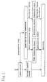
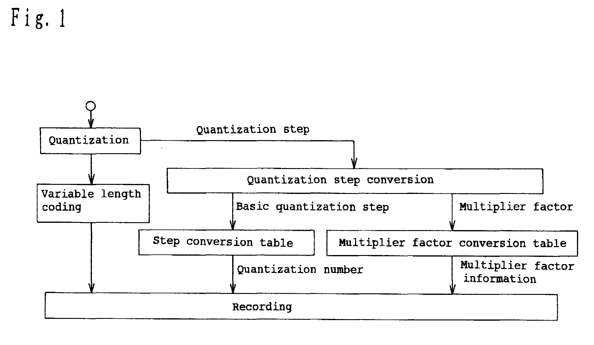
- FIG. 1 is an explanatory view for explaining the video signal recording method according to the embodiment 1.
- the number of quantization steps that allows for the recording is 15 kinds, as represented in terms of four bits, and the number of quantization steps for use in the quantization is 31 kinds, as represented in terms of five bits.
- an input signal is quantized, and a quantized signal and a quantization step used in the quantization, are output as the data.
- the quantized signal is variable length encoded and recorded together with the quantization step used, but because a greater number of quantization steps are used in this embodiment, they can not recorded directly. Therefore, the number of steps is reduced from 31 kinds to 15 kinds, employing the following method.
- the quantization step used in the quantization is divided into a basic quantization step and a multiplier factor, employing a table as shown in FIG. 2 (two tables are provided on account of space consideration). For example, if the quantization step used is 72, the basic quantization step is 18 and the multiplier factor is 4.
- the basic quantization step is converted into the quantization number, employing a table as shown in FIG. 3, and the multiplier factor is converted into the multiplier factor information, employing a table as shown in FIG. 4.
- the quantization step 18 and the multiplier factor 4 are converted into the quantization number 10 and the multiplier factor information 2, respectively.
- the quantization number and the multiplier factor information as obtained in this way are recorded together with the data obtained by variable length encoding the quantized signal.
- the location for recording the multiplier factor information as shown in the embodiment 1 is arbitrary.
- it may be a location for recording the class information in a unit of DCT block in the DVCPRO compression, which is unnecessary to implement a compression method for creating a DVCPRO bit stream which can be bit stream converted into an MPEG bit stream, as explained in this embodiment (in this case, the multiplier factor itself may be recorded instead of the multiplier factor information).
- the location for recording the quantization number of MPEG bit stream may be, for example, the location at which the quantization number of the original MPEG bit stream has been recorded. In this way, the number of quantization steps can be extended by recording the quantization number corresponding to the basic quantization step for determining the quantization step and the multiplier factor information indicating the multiplier factor.
- multiplier factor information is recorded in a unit of DCT block, it is possible to limit the range of an error within a DCT block where the error has occurred, even when the error has occurred in the multiplier factor information recorded.
- the quantization step, the basic quantization step, the multiplier factor, the quantization number, and the multiplier factor information as employed in the embodiment 1 and shown in FIGS. 2 to 4 are only illustrative.
- the quantization step for use may be a multiplication of the basic quantization step and the multiplier factor.
- the quantization step used in the quantization is converted into the quantization number and multiplier factor information which are recordable, as described above, the number of quantization steps for use in the quantization can be extended.
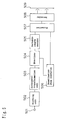
- FIG. 5 is a block diagram for explaining the configuration of the video signal recording apparatus in the embodiment 2.
- the recordable number of quantization steps is 15 kinds as represented in terms of four bits, and the number of quantization steps for use in the quantization is 31 kinds as represented in terms of five bits.
- reference numeral 501 denotes an input terminal for inputting a video signal
- reference numeral 502 denotes a blocking unit for dividing the input signal into blocks
- reference numeral 503 denotes an orthogonal transformation unit for making the discrete cosine transform of the input video signal
- reference numeral 504 denotes a quantizer for quantizing the video signal which has undergone the discrete cosine transform
- reference numeral 505 denotes a variable length encoder for variable length encoding the quantized video signal
- reference numeral 506 denotes a quantization step converter for converting the quantization step used in the quantization
- reference numeral 507 denotes a formatter for transforming the input signal into the recordable data format
- reference numeral 508 denotes a recorder for recording the input signal
- reference numeral 509 denotes a magnetic tape.
- the quantizer 504 corresponds to quantization means of the invention; the quantization step converter 506 corresponds to quantization information creating means of the invention; variable length encoder 505 corresponds to encoding means of the invention; and means comprising the formatter 507 and the recorder 508 corresponds to recording means of the invention.
- the blocking unit 502 divides a video signal input via the input terminal 501 into DCT blocks, and builds up a macro block by collecting a plurality of DCT blocks .
- the orthogonal transformation unit 503 performs the discrete cosine transform for the DCT blocks within the macro block for output to the quantizer 504.
- the quantizer 504 quantizes an alternating current component of a DCT block having undergone the discrete cosine transform within the macro block, which is an input signal, employing any quantization step among 31 kinds of quantization steps as shown in FIG. 2, and outputs the quantized signal to the variable length encoder 505 and the quantization step used to the quantization step converter 506, respectively.
- the quantization step converter 506 obtains the quantization number and the multiplier factor information from the input quantization step, employing the method as explained in the embodiment 1, and outputs them to the formatter 507. Also, the variable length encoder 505 applies the variable length coding to the alternating current component of the input signal for output to the formatter 507.
- the formatter 507 converts the direct current component of the input DCT block within the macro block which has undergone the discrete cosine transform, the alternating current component which is variable length encoded, the quantization number, and the multiplier factor information into the data format for recording and outputs them to the recorder 508.
- the recorder 508 records the input signal on the magnetic tape 509.
- the quantization step converter 506 converts the quantization step used in the quantization into the quantization number and the multiplier factor information which are recordable. In this way, the quantization step for use in the quantization can be extended. Also, by recording the multiplier factor information in a unit of DCT block, as previously described, it is possible to limit the range of an error within a DCT block where the error has occurred, even when the error has occurred in the recorded multiplier factor information.
- the location at which the multiplier factor information is recorded is also arbitrary.
- the multiplier factor itself may be recorded.
- the quantization step, the basic quantization step, the multiplier factor, the quantization number, and the multiplier factor information are only illustrative, as in the embodiment 1, and may take different values.
- the extension in this embodiment 2 is effective not only to the magnetic tape, but also to the data on the digital interface, which is output to the formatter 507.
- FIG. 6 is an explanatory view for explaining the video signal recording method according to the embodiment 3.
- the recordable number of quantization steps is 15 kinds as represented in terms of four bits, and the number of quantization steps for use in the quantization is 31 kinds as represented in terms of five bits.
- the bit precision of the AC component capable of variable length coding is nine bits, and the output of quantization is twelve bits.
- an input signal is quantized, and the quantized signal, and the quantization step used in the quantization are output as the data .
- the quantization step used can not be recorded directly owing to the same reason as in the embodiment 1.
- the number of quantization steps is reduced from 31 kinds to 15 kinds, with reference to FIGS. 2 and 3, owing to the same method as in the embodiment 1.
- the multiplier factor introduced to record the quantization step is represented by 2 to the C-th power (the multiplier factor in FIG. 2 is already set to 2 to the C-th power and may be used directly).
- the value of C takes three kinds, 0, 1 and 2.
- the bit precision of the AC component capable of variable length coding is nine bits, and the quantized output is twelve bits, as previously described.
- An input signal with an effective bit number of twelve bits has an effective bit number of twelve bits after being quantized.
- the effective bit number which can be treated with the variable length coding in this embodiment is nine bits, it is required that the effective number bit of the quantized input signal is reduced from twelve bits to nine bits.
- FIG. 7A is an explanatory view of the input signal which will undergo the D-range conversion
- FIG. 7B is an explanatory view of an output signal which has undergone the D-range conversion.
- the D-range absolute value excluding the sine bit s (see FIG. 7)
- the input signal of twelve bits is transformed into the data of nine bits and the multiplier factor by deleting upper bits and lower bits, depending on this value of D-range, as shown in FIG. 7.
- the value of 2 to the Z-th power is produced as the multiplier factor, in proportion to the number of bits in deleted lower bits.
- the Z value takes four kinds, 0, 1, 2 and 3 in the conversion from twelve bits to nine bits in this embodiment.
- the overall multiplier factor information in the embodiment 3 is obtained by adding this Z and an power exponent (coefficient) C of a multiplier factor represented as the power of 2 as explained in the embodiment 1.
- the value of C is equal to 1 or 2 when the quantization step is 10 or greater (see FIG. 2).
- the value of Z is always equal to zero (see FIG. 7)
- the overall multiplier factor information which is a sum of Z and C is either 1 or 2. As shown in FIG.
- the overall multiplier factor information which is a sum of Z and C is equal to 0, 1, 2 or 3 in this case (because the value of Z is 3 at maximum, when the quantization step is 1; the value of Z is 2 at maximum, when the quantization step is 2 ; the value of Z is 1 at maximum, when the quantization step is 4; and the value of Z is always zero, when the quantization step is 8).
- the overall multiplier factor information is 0, 1, 2 or 3, and can be represented in terms of within two bits.
- the overall multiplier factor information can be recorded in two bits of the class information in a unit of DCT block which is not employed in the DVCPRO compression as explained in this embodiment (refer to Japanese Patent Laid-Open No. 11-264521).
- the quantization number as represented (see FIG. 3) by any number of 1 to 15 can be recorded in four bits where the quantization number of the DVCPRO compression is recorded, and the quantization number corresponding to the basic quantization step for determining the quantization step and the overall multiplier factor information indicating the multiplier factor is recorded, whereby the number of quantization steps and the effective bit number of the AC component after quantization can be extended in the same recording format as that of the DVCPRO compression as explained in this embodiment.
- the overall multiplier factor information and the quantization number are recorded together with the data obtained by variable length coding the video signal which has been D-range converted.
- the overall multiplier factor information is also recorded in a unit of DCT block.
- the quantization step used in the quantization is converted into the quantization number and the multiplier factor which are recordable. Further, the quantized signal is converted into the data with a smaller effective bit number and the multiplier factor by the D-range conversion, and the overall multiplier factor information obtained by adding these two kinds of multiplier factors is recorded, whereby changes of the number of quantization step used in the quantization and the dynamic range of the quantized data can be made.
- the D-range extension is performed in a unit of DCT block, but may be made in a unit of macro block.
- the overall multiplier factor information is recorded in a unit of DCT block, whereby it is possible to limit the range of an error within a DCT block where the error has occurred, even if the error has occurred in the overall multiplier factor information recorded.
- the location at which the overall multiplier factor information is recorded is also arbitrary.
- the multiplier factor (i.e., 2 to the power of the overall multiplier factor information) itself may be recorded.
- the quantization step, the basic quantization step, the multiplier factor, the quantization number, and the overall multiplier factor information are only illustrative, as in the embodiment 1, and may take different values . In effect, the quantization step used may be a multiplication of the basic quantization step and the multiplier factor.
- FIG. 8 is a block diagram for explaining the configuration of the video signal recording apparatus in the embodiment 4.
- the recordable number of quantization steps is 15 kinds as represented in terms of four bits, and the number of quantization steps for use in the quantization is 31 kinds as represented in terms of five bits.
- the bit precision of the AC component capable of variable length coding is nine bits, and the output of quantization is twelve bits.
- reference numeral 801 denotes an input terminal for inputting a video signal
- reference numeral 802 denotes a blocking unit for dividing the input signal into blocks
- reference numeral 803 denotes an orthogonal transformation unit for making the discrete cosine transform of an input video signal
- reference numeral 804 denotes a quantizer for quantizing the video signal which has undergone the discrete cosine transform
- reference numeral 805 denotes a D-range converter for making the D-range conversion for the quantized signal
- reference numeral 806 denotes a variable length encoder for variable length coding the video signal which has been D-range converted
- reference numeral 807 denotes a quantization step converter for converting the quantization step used in the quantization
- reference numeral 808 denotes an adder for adding the signal produced by the quantization step conversion and the signal produced by the D-range conversion
- reference numeral 809 denotes a formatter for converting the input signal into the recordable data format
- the quantizer 804 corresponds to quantization means of the invention
- the D-range converter 805 corresponds to the range converting means of the invention
- means comprising the quantization step converter 807 and the adder 808 corresponds to quantization information creating means of the invention
- variable length encoder 806 corresponds to encoding means of the invention
- means comprising the formatter 809 and the recorder 810 corresponds to recording means of the invention.
- the blocking unit 802 divides a video signal input via the input terminal 801 into DCT blocks, and builds up a macro block by collecting a plurality of DCT blocks .
- the orthogonal transformation unit 803 performs the discrete cosine transform for the DCT blocks within the macro block, and outputs the transformed DCT blocks to the quantizer 804.
- the quantizer 804 quantizes an alternating current component of DCT blocks having undergone the discrete cosine transform within the macro block, which is the input signal, employing any quantization step among 31 kinds of quantization steps as shown in FIG. 2, and outputs the quantized signal to the D-range converter 805 and the quantization step used to the quantization step converter 807, respectively.
- the quantization step converter 807 calculates the quantization number and the power exponent (coefficient) C of the multiplier factor as represented in the C-th power of 2 from the input quantization step, employing the method explained in the embodiment 3, and outputs the quantization number to the formatter 809, and the value of C to the adder 808, respectively.
- the D-range converter 805 converts an alternating current component of the input signal for output to the variable length encoder 806, employing a method as explained in the embodiment 3, and calculates the value of the power exponent (coefficient) Z of the multiplier factor for output to the adder 808.
- the adder 808 calculates a sum of C and Z which are input, and outputs the sum to the formatter 809. Also, the variable length encoder 806 applies the variable length coding to the alternating current component of the input signal which has undergone the D-range conversion and outputs the encoded alternating current component to the formatter 809.
- the formatter 809 transforms the direct current component of input DCT block within the macro block which has undergone the discrete cosine transform, the alternating current component which has undergone the variable length coding, the quantization number, and the multiplier factor information into the data format for recording and outputs them to the recorder 810.
- the recorder 810 records the input signal on the magnetic tape 811. Note that the multiplier factor information is recorded in accordance with the unit used in the D-range extension in this embodiment.
- the quantization step converter 807 transforms the quantization step used in the quantization into the quantization number and the multiplier factor which are recordable.
- the D-range converter 805 converts the quantized signal into the data with a smaller effective bit number and the multiplier factor by the D-range conversion.
- the adder 808 creates the overall multiplier factor information obtained by adding these two kinds of multiplier factors. In this way, changes of the number of quantization step used in the quantization and the dynamic range of the quantized data can be made.
- the D-range extension is performed in a unit of DCT block, but may be made in a unit of macro block.
- the overall multiplier factor information is recorded in a unit of DCT block, whereby it is possible to limit the range of an error within a DCT block where the error has occurred, even if the error has occurred in the overall multiplier factor information recorded.
- the location at which the overall multiplier factor information is recorded is also arbitrary.
- the multiplier factor i.e., 2 to the power of the overall multiplier factor information
- the quantization step, the basic quantization step, the multiplier factor, the quantization number, and the overall multiplier factor information are only illustrative, as in the embodiment 3, and may take different values.
- the extension in this embodiment 4 is effective not only to the magnetic tape, but also to the data on the digital interface, which is output to the formatter 809.
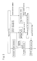
- FIG. 9 is an explanatory view for explaining the video signal reproducing method according to the embodiment 5.
- This embodiment 5 involves a new video signal reproducing method for reproducing the signal recorded by quantizing each DCT block within a macro block in the same quantization step, employing the video signal recording method as explained in the embodiments 3 and 4.
- This signal inversely formatted (reproduced) is composed of a variable length encoded signal, the overall multiplier factor information and the quantization number, as will be described later in the embodiment 6.
- variable length encoded signal is decoded in variable length, and the D-range extension is performed, employing a value subtracted by the value M.
- the effective bit number of the signal decoded in variable length is Y bits
- the quantization number is converted into the basic quantization step with reference to a table of FIG. 3, and the quantization step is configured, employing the value M (i.e., the product of the basic quantization step and the M-th power of 2 is the quantization step) .
- M i.e., the product of the basic quantization step and the M-th power of 2 is the quantization step
- the inverse quantization of the signal of X bits D-range extended is performed, employing this quantization step.
- the inversely quantized signal is subjected to the inverse discrete cosine transform and the inverse blocking, and output as a reproduced signal, as will be described later in the embodiment 6.
- the inverse quantization is made, employing the quantization step of 14 in either case (because the minimum value of the overall multiplier factor is one in either case) .
- the overall multiplier factor information itself i.e. , one
- the basic quantization step i.e., 7
- the quantization step should be a greater value, and it is beneficial to make use of a not greater value among the minimum value of the overall multiplier factor information C+Z and the maximum value (herein, 2) which the multiplier factor information C for specifying the multiplier factor to be combined with the basic quantization step can take. This is the reason for using a not greater value M among the minimum value of the overall multiplier factor information and the maximum value which the multiplier factor information for specifying the multiplier factor to be combined with the basic quantization step can take in this embodiment.
- a not greater value M among the minimum value of the overall multiplier factor information and the maximum value which the multiplier factor information for specifying the multiplier factor to be combined with the basic quantization step can take is obtained, and by reflecting its result, the quantization step is configured to be larger, whereby the code amount after the MPEG transcode can be reduced.
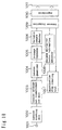
- FIG. 10 is a block diagram for explaining the configuration of the video signal reproducing apparatus according to the embodiment 6.
- the video signal recording method as explained in the embodiments 3 and 4 is employed to quantize each DCT block within a macro block by using the same quantization step to reproduce a signal.
- reference numeral 1011 denotes a magnetic tape on which the signal is recorded
- reference numeral 1010 denotes a reproducer for reproducing a signal from the magnetic tape
- reference numeral 1009 denotes an inverse formatter for inversely formatting the required information from the reproduced signal
- reference numeral 1008 denotes a minimum multiplier factor information detector for detecting a minimum value of the overall multiplier factor information that has been input
- reference numeral 1007 denotes a quantization step creating unit for creating the quantization step from an input signal
- reference numeral 1006 denotes a variable length decoder for variable length decoding the input signal
- reference numeral 1005 denotes a D-range extender for extending the D-range of the input signal
- reference numeral 1004 denotes an inverse quantizer for inversely quantizing the input signal
- reference numeral 1003 denotes an orthogonal transformer for making the inverse discrete cosine transform of the input signal
- reference numeral 1002 denotes an inverse blocking
- the inverse quantizer 1004 corresponds to inverse quantizing means of the invention
- the D-range expander 805 corresponds to inverse range convertingmeans of the invention
- means comprising the quantization step creating unit 1007 and the minimum multiplier factor information detector 1008 corresponds to quantization step constructing means of the invention
- means comprising the inverse formatter 1009 and the reproducer 1010 corresponds to reproducing means of the invention.
- the reproducer 1010 reproduces the information from the magnetic tape 1011, and outputs the reproduced information to the inverse formatter 1009.
- the inverse formatter 1009 makes the inverse formatting to reproduce the direct current component, the alternating current component that is variable length encoded, the quantization number, and the overall multiplier factor information from the information reproduced by the reproducer 1010.
- the minimum multiplier factor information detector 1008 detects the minimum value of the overall multiplier factor information, employing the method as described in the embodiment 5, and outputs a not greater value among the minimum value of the overall multiplier factor information C+Z and the maximum value which the multiplier factor information C for specifying the multiplier factor to be combined with the basic quantization step can take to the D-range expander 1005 and the quantization step creating unit 1007.
- the quantization step creating unit 1007 constructs the quantization step, employing the method as described in the embodiment 5, and outputs the constructed quantization step to the inverse quantizer 1004.
- variable length decoder 1006 variable length decodes the reproduced alternating current component for output to the D-range expander 1005. Also, the D-range expander 1005 D-range extends the alternating current component input from the variable length decoder 1006, employing the method as described in the embodiment 5, for output to the inverse quantizer 1004.
- the inverse quantizer 1004 inversely quantizes the alternating current component which is D-range extended by the D-range expander 1005, using the quantization step input from the quantization step creating unit 1007, and outputs this to the inverse orthogonal transformer 1003.
- the inverse orthogonal transformer 1003 makes the inverse discrete cosine transform of the alternating current component input from the inverse quantizer 1004 and the direct current component reproduced by the inverse formatter 1009 and input through the same path as the alternating current component, for output to the inverse blocking unit 1002.
- the inverse blocking unit 1002 unblocks a blocked signal, and outputs the reproduced signal to the output terminal 1001.
- the minimum multiplier factor information detector 1008 calculates the minimum value of the overall multiplier factor information, and the quantization step creating unit 1007 constructs the quantization step to be greater by reflecting the result. In this way, the code amount after the MPEG transcode can be reduced. In this embodiment, the signal can be decoded without obtaining the minimum value of the overall multiplier factor information. Since the minimum value multiplier factor detector 1008 can be dispensed with in such case of decoding, the configuration of the video signal reproducing apparatus can be simplified.
- the recordable number of quantization steps is 15 kinds as represented in terms of four bits, the number of quantization steps for use in the quantization is 31 kinds as represented in terms of five bits.
- the bit precision of the AC component capable of variable length coding is nine bits, and the output of quantization is twelve bits.
- those values are adopted for explanation of the specific example, and the present invention is not limited thereto.
- the multiplier factor to be combined with the basic quantization step of the invention is the power of 2 in the above embodiments, the invention is not limited thereto but may take arbitrary number for such multiplier factor.
- the overall multiplier factor information is a sum of the power exponent of the multiplier factor to be combined with the basic quantization step which is the power of 2, and the power exponent of the range conversion multiplier factor.
- the invention is not limited thereto, but the overall multiplier factor information may be a pair of the multiplier factor to be combined with the basic quantization step which is not the power of 2 and the range conversion multiplier factor itself, for example.
- the quantization step used in the quantization of the signal according to the invention is uniform in the macro block composed of DCT blocks in the above embodiments, but may be different in each DCT block within the macro block, for example.
- the quantized signal of the invention is range converted in the above embodiments, butmay not be range converted, unless required. In the reproduction of such signal, the inverse range conversion is not necessary to perform, and the signal reproducing apparatus of the invention may not have the inverse range converting means.
- a medium for carrying a program and/or the data for enabling a computer to execute all or some functions provided for means in whole or part of the above embodiments is produced, and may be used to enable the computer to perform the above operation in accordance with the read program and/or the data.
- An information assembly for carrying a program and/or the data for enabling a computer to execute all or some functions provided for means in whole or part of the above embodiments is produced, and may be used to enable the computer to perform the above operation in accordance with the read program and/or the data structure.
- the data involves the data structure, the data format, and the kind of data.
- the medium involves the recording medium such as ROM, the transmission medium for the Internet, and the transmission medium for light, radio wave and sound wave.
- the carrying medium involves the recording medium for recording the program and/or the data, and the transmission medium for transmitting the program and/or the data, for example.
- To be processable by the computer means to be readable by the computer in the case of the recording medium such as ROM, or to be handleable by the computer as a result of transmitting the program and/or the data in the case of the transmission medium.
- the information assembly involves the software such as the program and/or the data, for example.
- the video signal recording method of the invention comprises quantizing an input video signal employing L (L ⁇ M ⁇ N) kinds of quantization steps among MXN kinds of quantization steps of which the values are determined by the multiplication of M kinds (M ⁇ 1) of basic quantization steps and N kinds (N ⁇ 1) of multiplier factors, wherein the quantized signal is variable length encoded, the quantization number corresponding to the basic quantization step for determining the quantization step used in the quantization, the multiplier factor information corresponding to the multiplier factor, and the variable length encoded signal are recorded.
- the number of quantization steps can be extended in the same recording format as employed in the DVCPRO compression.
- the video signal recording apparatus of the invention comprises block division means of dividing an input video signal into DCT blocks and constructing a macro block from a plurality of DCT blocks, discrete cosine transform means of discrete cosine transforming each DCT block within the macro block, quantization means of quantizing an alternating current component of DCT block which has undergone the discrete cosine transform employing L (L ⁇ M ⁇ N) kinds of quantization steps among MXN kinds of quantization steps of which the values are determined by the multiplication of M kinds (M ⁇ 1) of basic quantization steps and N kinds (N ⁇ 1) of multiplier factors , quantization information determination means of determining the quantization number corresponding to the basic quantization step and the multiplier factor information corresponding to the multiplier factor for determining the quantization step used in the quantization means, variable length coding means of variable length coding the alternating current signal quantized, and recording means of recording the direct current component of DCT block which has undergone the discrete cosine transform, the alternating current signal which is variable length encoded,
- a video signal reproducing method of the invention for reproducing a video signal recorded in accordance with the video signal recording method of the invention comprises reproducing the variable length encoded signal recorded, the quantization number and the overall multiplier factor information, and making the inverse quantization by variable length decoding the variable length encoded signal, employing the quantization step which is obtained by multiplying the basic quantization step corresponding to the quantization number by (2 to the P-th power) with the coefficient P corresponding to the overall multiplier factor information.
- the signal recorded in accordance with the video signal recording method of the invention can be reproduced.
- the minimum value of the overall multiplier factor information the signal can be decoded with the reduced code amount transformed into the MPEG bit stream.
- a video signal reproducing apparatus of the invention which for example reproduces a video signal recorded by the video signal recording apparatus of the invention, comprises reproduction means of reproducing the direct current component recorded in a unit of macro block composed of a plurality of DCTblocks, the alternating current component which is variable length encoded, the quantization number and the overall multiplier factor information, variable length decoding means of variable length decoding the alternating current component which is variable length encoded to create an alternating current signal, quantization step determining means of determining the quantization step by calculating the basic quantization step corresponding to the quantization number and the exponent P corresponding to the overall multiplier factor information and multiplying the basic quantization step by (2 to the P-th power), and inverse quantization means of inversely quantizing the alternating current component with the quantization step.
- the video signal reproducing apparatus of the invention can exhibit the same effect as obtained with the video signal reproducing method of the invention.
- the present invention can provide a signal recording apparatus, a signal recording method, a signal reproducing apparatus, a signal reproducing method, a medium, and an information assembly, which are capable of changing a compression method with less degradation of data than conventionally.
- the present invention has the advantage of implementing the compression method which is capable of extending the number of quantization steps.
Landscapes
- Engineering & Computer Science (AREA)
- Multimedia (AREA)
- Signal Processing (AREA)
- Compression Or Coding Systems Of Tv Signals (AREA)
- Television Signal Processing For Recording (AREA)
- Signal Processing For Digital Recording And Reproducing (AREA)
Abstract
Description
said data is a quantization number for specifying said basic quantization step and the multiplier factor information for specifying said multiplier factor to be combined with said basic quantization step.
wherein said data has the information regarding said range conversion multiplier factor.
and said overall multiplier factor information is a sum of its power exponent and the power exponent of the range conversion multiplier factor represented as the power of 2.
said overall multiplier factor information is a sum of its power exponent and the power exponent of the range conversion multiplier factor represented as said power of 2.
- 501, 801
- Input terminal
- 502, 802
- Blocking unit
- 503, 803
- Orthogonal transformation unit
- 504, 804
- Quantizer
- 505, 806
- Variable length encoder
- 506, 807
- Quantization step converter
- 507, 809
- Formatter
- 508, 810
- Recorder
- 509, 811, 1011
- Magnetic tape
- 805
- D-range converter
- 808
- Adder
- 1001
- Output terminal
- 1002
- Inverse blocking unit
- 1003
- Inverse orthogonal transformation unit
- 1004
- Inverse quantizer
- 1005
- D-range expander
- 1006
- Variable length decoder
- 1007
- Quantization step creating unit
- 1008
- Minimum multiplier factor information detector
- 1009
- Inverse formatter
- 1010
- Reproducer
Claims (20)
- A signal recording apparatus, comprising:quantization means of quantizing a signal employing a quantization step;quantization information creating means of creating plural pieces of quantization information to specify said quantization step;encoding means of generating an encoded signal from said quantized signal; andrecording means of recording a compressed signal having data containing saidplural pieces of quantization information and said encoded signal.
- The signal recording apparatus according to claim 1, wherein said quantization step is a product of a basic quantization step and a multiplier factor to be combined with said basic quantization step, and
said data is a quantization number for specifying said basic quantization step and the multiplier factor information for specifying said multiplier factor to be combined with said basic quantization step. - The signal recording apparatus according to claim 2, wherein said quantization step is uniform in a macro block comprised of DCT blocks,said quantization number is recorded for each said macro block, andsaid multiplier factor information is recorded for each said DCT block.
- The signal recording apparatus according to claim 1, further comprising range conversion means of range converting said quantized signal using a range conversion multiplier factor which is represented as the power of 2,
wherein said data has the information regarding said range conversion multiplier factor. - The signal recording apparatus according to claim 4, wherein said quantization step is a product of a basic quantization step and a multiplier factor to be combined with said basic quantization step, andsaid plural pieces of quantization information are a quantization number for specifying said basic quantization step and the multiplier factor information for specifying said multiplier factor to be combined with said basic quantization step,wherein the information involving the range conversion multiplier factor means the overall multiplier factor information consisting of the information regarding the range conversion multiplier factor and the information on the basis of said multiplier factor information.
- The signal recording apparatus according to claim 5, wherein the multiplier factor to be combined with said basic quantization step is the power of 2, said multiplier factor information being the power exponent,
and said overall multiplier factor information is a sum of its power exponent and the power exponent of the range conversion multiplier factor represented as the power of 2. - The signal recording apparatus according to claim 6, wherein said quantization step is uniform in a macro block comprised of DCT blocks,said quantization number is recorded for each said macro block, andsaid sum is recorded for each said DCT block.
- The signal recording apparatus according to claim 7, wherein said signal has 12 bits,said range converted signal has 9 bits, andsaid overall multiplier factor information has 2 bits or less.
- A signal recording method, comprising the steps of:quantizing a signal employing a quantization step;creating plural pieces of quantization information to specify said quantization step;generating an encoded signal from said quantized signal; andrecording a compressed signal having data containing said plural pieces of quantization information and said encoded signal.
- A signal reproducing apparatus, comprising:reproduction means of reproducing the data containing plural pieces of quantization information for specifying a quantization step used in quantizing the signal and an encoded signal to be generated from said quantized signal from a compressed signal recorded as a signal having the data and said encoded signal;quantization step configuration means of configuring a quantization step on the basis of plural pieces of said reproduced quantization information; andinverse quantization means of making the inverse quantization in accordance with said configured quantization step on the basis of said reproduced encoded signal.
- The signal reproducing apparatus according to claim 10, wherein said quantized signal is range converted using a range conversion multiplier factor which is represented as the power of 2, andsaid data has the information regarding said range conversion multiplier factor,said signal reproducing apparatus comprising inverse range conversion means of making the inverse range conversion on the basis of said encoded signal and the information regarding said range conversion multiplier factor,said inverse quantization in accordance with said configured quantization step being effected for said signal which has undergone the inverse range conversion on the basis of said encoded signal.
- The signal reproducing apparatus according to claim 11, wherein said quantization step used in quantizing the signal is a product of a basic quantization step and a multiplier factor to be combined with said basic quantization step, andsaid plural pieces of quantization information is a quantization number for specifying said basic quantization step and the multiplier factor information for specifying said multiplier factor to be combined with said basic quantization step,wherein the information involving said range conversion multiplier factor means the overall multiplier factor information consisting of the information regarding its range conversion multiplier factor and the information on the basis of said multiplier factor information.
- The signal reproducing apparatus according to claim 12, wherein the multiplier factor to be combined with said basic quantization step is the power of 2, said multiplier factor information being the power exponent, and
said overall multiplier factor information is a sum of its power exponent and the power exponent of the range conversion multiplier factor represented as said power of 2. - The signal reproducing apparatus according to claim 13, wherein said quantization step used in quantizing said signal is uniform in a macro block composed of DCT blocks,said quantization number is recorded for each said macro block, andsaid sum is recorded for each said DCT block.
- The signal reproducing apparatus according to claim 14, wherein said quantization step configured is a product of a not greater value among the minimum value of the sums recorded for said DCT blocks within said macro block and the maximum value which the multiplier factor information for specifying the multiplier factor to be combined with the basic quantization step can take, and a quantization number recorded for each said macro block.
- A signal reproducing method, comprising the steps of:reproducing the data containing plural pieces of quantization information for specifying a quantization step used in quantizing a signal and an encoded signal to be generated from said quantized signal from a compressed signal recorded as a signal having the data and said encoded signal;configuring the quantization step on the basis of plural pieces of said quantization information reproduced; andmaking the inverse quantization in accordance with said configured quantization step on the basis of said reproduced encoded signal.
- A medium for carrying a program and/or the data for enabling a computer to execute all or some functions provided for means in whole or part of the invention according to any one of claims 1 to 8 and 10 to 15, wherein said medium can be processed by said computer.
- A medium for carrying a program and/or the data for enabling a computer to execute all or some operations provided for steps in whole or part of the invention according to claim 9 or 16, wherein said medium can be processed by said computer.
- An information assembly which is a program and/or the data for enabling a computer to execute all or some functions provided for means in whole or part of the invention according to any one of claims 1 to 8 and 10 to 15.
- An information assembly which is a program and/or the data for enabling a computer to execute all or some operations provided for steps in whole or part of the invention according to claim 9 or 16.
Applications Claiming Priority (2)
| Application Number | Priority Date | Filing Date | Title |
|---|---|---|---|
| JP2000075789A JP4297235B2 (en) | 2000-03-17 | 2000-03-17 | Signal recording apparatus, signal recording method, signal reproducing apparatus, signal reproducing method, and recording medium |
| JP2000075789 | 2000-03-17 |
Publications (2)
| Publication Number | Publication Date |
|---|---|
| EP1137288A2 true EP1137288A2 (en) | 2001-09-26 |
| EP1137288A3 EP1137288A3 (en) | 2004-09-29 |
Family
ID=18593626
Family Applications (1)
| Application Number | Title | Priority Date | Filing Date |
|---|---|---|---|
| EP20010106725 Withdrawn EP1137288A3 (en) | 2000-03-17 | 2001-03-16 | Method and apparatus for bit stream conversion |
Country Status (4)
| Country | Link |
|---|---|
| US (1) | US7190884B2 (en) |
| EP (1) | EP1137288A3 (en) |
| JP (1) | JP4297235B2 (en) |
| CN (1) | CN1292590C (en) |
Cited By (1)
| Publication number | Priority date | Publication date | Assignee | Title |
|---|---|---|---|---|
| EP4005203A4 (en) * | 2020-06-05 | 2022-08-17 | Tencent America LLC | QUANTIFIER DESIGN |
Families Citing this family (6)
| Publication number | Priority date | Publication date | Assignee | Title |
|---|---|---|---|---|
| WO2006093306A1 (en) * | 2005-03-03 | 2006-09-08 | Pioneer Corporation | Image encoding method conversion device and method |
| CN102132569A (en) * | 2008-09-29 | 2011-07-20 | 松下电器产业株式会社 | Image encoding device, image encoding method, and imaging system |
| US8905760B2 (en) * | 2008-11-04 | 2014-12-09 | Duane C. Keller | Methods and systems for progressively treating and controlling oral periopathogens causing systemic inflammations |
| US8956161B2 (en) | 2008-11-04 | 2015-02-17 | Duane C Keller | Article and method for controlling oral-originated systemic disease |
| US8591229B2 (en) | 2010-12-16 | 2013-11-26 | Duane C. Keller | Devices and methods for creating a positive pressure environment for treatment of oral biofilms associated with periodontal disease |
| MX339741B (en) * | 2012-11-19 | 2016-06-07 | Lg Electronics Inc | Signal transceiving apparatus and signal transceiving method. |
Family Cites Families (11)
| Publication number | Priority date | Publication date | Assignee | Title |
|---|---|---|---|---|
| US5594598A (en) * | 1992-10-19 | 1997-01-14 | Canon Kabushiki Kaisha | Information recording apparatus having variable compression ratio |
| JP3689437B2 (en) | 1992-10-29 | 2005-08-31 | ソニー株式会社 | Image signal encoding method and apparatus |
| JP3106749B2 (en) * | 1992-12-10 | 2000-11-06 | ソニー株式会社 | Adaptive dynamic range coding device |
| KR940026915A (en) * | 1993-05-24 | 1994-12-10 | 오오가 노리오 | Digital video signal recording device and playback device and recording method |
| US5654760A (en) * | 1994-03-30 | 1997-08-05 | Sony Corporation | Selection of quantization step size in accordance with predicted quantization noise |
| JPH08256341A (en) * | 1995-03-17 | 1996-10-01 | Sony Corp | Image signal encoding method, image signal encoding device, image signal recording medium, and image signal decoding device |
| US5809200A (en) * | 1995-08-07 | 1998-09-15 | Victor Company Of Japan, Ltd. | Video signal recording apparatus |
| US5731837A (en) * | 1996-01-25 | 1998-03-24 | Thomson Multimedia, S.A. | Quantization circuitry as for video signal compression systems |
| JP2000165879A (en) | 1998-09-22 | 2000-06-16 | Matsushita Electric Ind Co Ltd | Video signal encoding method, video signal encoding device, and program recording medium |
| DE19909565A1 (en) | 1999-03-04 | 2000-10-05 | Siemens Ag | Process for monitoring the operation of optical fibers |
| US6944226B1 (en) | 2000-10-03 | 2005-09-13 | Matsushita Electric Corporation Of America | System and associated method for transcoding discrete cosine transform coded signals |
-
2000
- 2000-03-17 JP JP2000075789A patent/JP4297235B2/en not_active Expired - Fee Related
-
2001
- 2001-03-16 EP EP20010106725 patent/EP1137288A3/en not_active Withdrawn
- 2001-03-16 CN CNB01112007XA patent/CN1292590C/en not_active Expired - Fee Related
- 2001-03-19 US US09/811,682 patent/US7190884B2/en not_active Expired - Fee Related
Cited By (1)
| Publication number | Priority date | Publication date | Assignee | Title |
|---|---|---|---|---|
| EP4005203A4 (en) * | 2020-06-05 | 2022-08-17 | Tencent America LLC | QUANTIFIER DESIGN |
Also Published As
| Publication number | Publication date |
|---|---|
| JP4297235B2 (en) | 2009-07-15 |
| CN1292590C (en) | 2006-12-27 |
| CN1319994A (en) | 2001-10-31 |
| JP2001268514A (en) | 2001-09-28 |
| US20010024569A1 (en) | 2001-09-27 |
| EP1137288A3 (en) | 2004-09-29 |
| US7190884B2 (en) | 2007-03-13 |
Similar Documents
| Publication | Publication Date | Title |
|---|---|---|
| AU2010200907B2 (en) | Variable length coding method and variable length decoding method | |
| JP3380810B2 (en) | Image coding method | |
| US7133832B2 (en) | Recording and reproducing apparatus for use with optical recording medium having real-time, losslessly encoded data | |
| CN1366778A (en) | Video compression | |
| EP0369682A2 (en) | Efficient coding method and its decoding method | |
| EP0542196A2 (en) | Digital video signal recording and reproducing apparatus | |
| KR100272120B1 (en) | Quantization control circuit | |
| US7190884B2 (en) | Signal recording apparatus and method, signal reproducing apparatus and method, medium, and information assembly | |
| US5043809A (en) | Encoding apparatus | |
| US20020122483A1 (en) | Encoding circuit and method | |
| KR20030062229A (en) | Method and apparatus for run-length encoding video data | |
| JPH07153195A (en) | Digital recording device | |
| KR100200627B1 (en) | Video signal compression encoding device | |
| JPH1188183A (en) | Wavelet converter, its method, wavelet inverse converter, its method, image coder, its method, image decoder and its method | |
| JP2004007380A (en) | Method and apparatus for encoding and decoding key data | |
| JP3136523B2 (en) | Image conversion device | |
| JP3446056B2 (en) | Data division device | |
| JPS62193382A (en) | System and device for encoding and decoding picture signal | |
| JPH10313458A (en) | Image data conversion apparatus and method, prediction coefficient generation apparatus and method, prediction coefficient storage medium | |
| JPH07146927A (en) | Image file device | |
| JPH04239272A (en) | Compression and expansion equipment | |
| JPH0983378A (en) | Encoding device and decoding device | |
| JPH06189283A (en) | Transmitting device for digital picture signal | |
| JPH06334990A (en) | Encoding circuit and decoding circuit for digital video signal | |
| JPS62193380A (en) | System and device for encoding and decoding picture signal |
Legal Events
| Date | Code | Title | Description |
|---|---|---|---|
| PUAI | Public reference made under article 153(3) epc to a published international application that has entered the european phase |
Free format text: ORIGINAL CODE: 0009012 |
|
| AK | Designated contracting states |
Kind code of ref document: A2 Designated state(s): AT BE CH CY DE DK ES FI FR GB GR IE IT LI LU MC NL PT SE TR |
|
| AX | Request for extension of the european patent |
Free format text: AL;LT;LV;MK;RO;SI |
|
| PUAL | Search report despatched |
Free format text: ORIGINAL CODE: 0009013 |
|
| AK | Designated contracting states |
Kind code of ref document: A3 Designated state(s): AT BE CH CY DE DK ES FI FR GB GR IE IT LI LU MC NL PT SE TR |
|
| AX | Request for extension of the european patent |
Extension state: AL LT LV MK RO SI |
|
| 17P | Request for examination filed |
Effective date: 20041227 |
|
| 17Q | First examination report despatched |
Effective date: 20050331 |
|
| AKX | Designation fees paid |
Designated state(s): DE FR |
|
| RAP1 | Party data changed (applicant data changed or rights of an application transferred) |
Owner name: PANASONIC CORPORATION |
|
| STAA | Information on the status of an ep patent application or granted ep patent |
Free format text: STATUS: THE APPLICATION HAS BEEN WITHDRAWN |
|
| 18W | Application withdrawn |
Effective date: 20110517 |