EP1137222A1 - Method of controlling device, transmission device, and medium - Google Patents
Method of controlling device, transmission device, and medium Download PDFInfo
- Publication number
- EP1137222A1 EP1137222A1 EP00964655A EP00964655A EP1137222A1 EP 1137222 A1 EP1137222 A1 EP 1137222A1 EP 00964655 A EP00964655 A EP 00964655A EP 00964655 A EP00964655 A EP 00964655A EP 1137222 A1 EP1137222 A1 EP 1137222A1
- Authority
- EP
- European Patent Office
- Prior art keywords
- equipment
- data
- bus line
- command
- input
- Prior art date
- Legal status (The legal status is an assumption and is not a legal conclusion. Google has not performed a legal analysis and makes no representation as to the accuracy of the status listed.)
- Withdrawn
Links
Images











Classifications
-
- H—ELECTRICITY
- H04—ELECTRIC COMMUNICATION TECHNIQUE
- H04L—TRANSMISSION OF DIGITAL INFORMATION, e.g. TELEGRAPHIC COMMUNICATION
- H04L12/00—Data switching networks
- H04L12/28—Data switching networks characterised by path configuration, e.g. LAN [Local Area Networks] or WAN [Wide Area Networks]
- H04L12/40—Bus networks
-
- H—ELECTRICITY
- H04—ELECTRIC COMMUNICATION TECHNIQUE
- H04L—TRANSMISSION OF DIGITAL INFORMATION, e.g. TELEGRAPHIC COMMUNICATION
- H04L12/00—Data switching networks
- H04L12/28—Data switching networks characterised by path configuration, e.g. LAN [Local Area Networks] or WAN [Wide Area Networks]
- H04L12/40—Bus networks
- H04L12/40052—High-speed IEEE 1394 serial bus
- H04L12/40117—Interconnection of audio or video/imaging devices
-
- H—ELECTRICITY
- H04—ELECTRIC COMMUNICATION TECHNIQUE
- H04L—TRANSMISSION OF DIGITAL INFORMATION, e.g. TELEGRAPHIC COMMUNICATION
- H04L12/00—Data switching networks
- H04L12/28—Data switching networks characterised by path configuration, e.g. LAN [Local Area Networks] or WAN [Wide Area Networks]
- H04L12/40—Bus networks
- H04L12/40052—High-speed IEEE 1394 serial bus
- H04L12/40065—Bandwidth and channel allocation
-
- H—ELECTRICITY
- H04—ELECTRIC COMMUNICATION TECHNIQUE
- H04L—TRANSMISSION OF DIGITAL INFORMATION, e.g. TELEGRAPHIC COMMUNICATION
- H04L12/00—Data switching networks
- H04L12/28—Data switching networks characterised by path configuration, e.g. LAN [Local Area Networks] or WAN [Wide Area Networks]
- H04L12/40—Bus networks
- H04L12/40052—High-speed IEEE 1394 serial bus
- H04L12/40123—Interconnection of computers and peripherals
-
- H—ELECTRICITY
- H04—ELECTRIC COMMUNICATION TECHNIQUE
- H04L—TRANSMISSION OF DIGITAL INFORMATION, e.g. TELEGRAPHIC COMMUNICATION
- H04L12/00—Data switching networks
- H04L12/28—Data switching networks characterised by path configuration, e.g. LAN [Local Area Networks] or WAN [Wide Area Networks]
- H04L12/40—Bus networks
- H04L12/40052—High-speed IEEE 1394 serial bus
- H04L12/40058—Isochronous transmission
-
- H—ELECTRICITY
- H04—ELECTRIC COMMUNICATION TECHNIQUE
- H04L—TRANSMISSION OF DIGITAL INFORMATION, e.g. TELEGRAPHIC COMMUNICATION
- H04L12/00—Data switching networks
- H04L12/28—Data switching networks characterised by path configuration, e.g. LAN [Local Area Networks] or WAN [Wide Area Networks]
- H04L12/40—Bus networks
- H04L12/40052—High-speed IEEE 1394 serial bus
- H04L12/40071—Packet processing; Packet format
Definitions
- the present invention relates to an equipment control method and a transmission apparatus which are applicable to a case where equipments connected through e.g. a serial communication bus according to IEEE 1394 system are controlled by each other and also relates to a medium in which a program for performing the control between the equipments connected through the serial communication bus is stored.
- AV equipments which are capable of transmitting information to each other through a network using the serial communication bus according to IEEE1394 system have hitherto been developed.
- this network it is possible to control AV equipments connected to the network by transmitting a prescribed command (AV/C Command Transaction Set: hereinafter referred to "AV/C command"). While details of the AV/C command will be described below, it is also described in AV/C Digital Interface Command Set General Specification which was laid open by 1394 Trade Association.
- An object of the present invention is to enable linking operations such as the autoplay to be efficiently performed between the equipments connected through the IEEE 1394 system bus and the like.
- a first invention in an equipment control method of performing the control between equipments connected through a predetermined bus line, setting on input selection at a first equipment is instructed from a second equipment through the bus line by a command of a predetermined format.
- the instructions about setting on input selection at the first equipment can previously be registered.
- Arranging in this way will enable a simple control using the previously registered instructions.
- the input signal source at one of the equipments can be simply specified by the other equipments.
- the second equipment when the second equipment desires to input an output of the first equipment, the second equipment inputs a signal from an input signal source which the second equipment specifies by the informed data.
- a fifth invention in an equipment control method of performing the control between equipments connected through a predetermined bus line, when data outputted from a first equipment can be inputted by a second equipment, data on an output route change of that data from the first equipment is transmitted to the second equipment through the bus line.
- Arranging in this way will enable the second equipment to cope with a change of output route in transmission through the bus line.
- the output route includes an output route other than the bus line.
- the second equipment can cope with a change to an output route other than the bus line and also with a change from an output route other than the bus line.
- a seventh invention in an equipment control method of the fifth invention, for the data on the output route change, at least two kinds of requests are prepared, a first request instructing the second equipment about input switching to the changed route and a second request not instructing about the input switching, but causing the second equipment to estimate only the route change.
- the second equipment can cope with a case where the input switching is instructed following a change of output route and also with a case where the input switching is not instructed.
- data transmission can be instructed to other equipment connected through the bus line and an equipment which has instructed can estimate by its instructions an output status of the equipment which has been instructed on the data transmission, thus allowing the equipment which has instructed to receive data transmitted to the bus line without fail.
- a transmission apparatus capable of data transmission with other equipment connected through a predetermined bus line, comprising
- Arranging in this way will enable a remote control of setting with respect to the input selection at other equipment connected through the bus line.
- the command instructing about setting on input selection produced by the command producing section is previously sent out from the sending section before the input selection is executed at the other equipment.
- a transmission apparatus capable of data transmission with other equipment connected through a predetermined bus line, comprising
- the input selection status at this transmission apparatus is informed to other equipments connected through the bus line, so that transmission status inside a network connected through the bus line can be estimated by other equipments.
- a transmission apparatus capable of data transmission with other equipment connected through a predetermined bus line, comprising
- the input selection status at other equipment connected through the bus line can be estimated and stored, so that the estimated equipment can be controlled satisfactorily.
- a transmission apparatus capable of data transmission with other equipment through a predetermined bus line, comprising
- the output route indicated by the command produced by the command producing section includes an output route other than the bus line.
- Arranging in this way will enable the equipment to cope with a change to an output route other than the bus line and also with a change from an output route other than the bus line.
- a command instructing about input switching to the changed route and a command not instructing about the input switching, but deciding only the route change are prepared.
- Arranging in this way will enable the equipment to cope with a case where the input switching is instructed following a change of the output route and also with a case where the input switching is not instructed.
- a transmission apparatus capable of data transmission with other equipment connected through a predetermined bus line, comprising
- Arranging in this way will enable the equipment to estimate and store the output route of data at other equipment connected through the bus line.
- the output route indicated by the command estimated in the data processing section includes an output route other than the bus line.
- Arranging in this way will enable the equipment to estimate even if an output route other than the bus line is used.
- a processing to switch to inputting data from the changed output route or a processing to only estimate the changed output route is selectively performed by that command.
- Arranging in this way will enable the equipment to cope with a case where the input switching is instructed following a change of the output route and also with a case where the input switching is not instructed.
- a transmission apparatus capable of data transmission with other equipment connected through a predetermined bus line, comprising
- a transmission apparatus capable of data transmission with other equipment connected through a predetermined bus line, comprising
- a transmission apparatus capable of data transmission with other equipment connected through a predetermined bus line, comprising
- a transmission apparatus capable of data transmission with other equipment connected through a predetermined bus line, comprising
- the program comprises the step of instructing about setting on input selection in a first equipment by means of a predetermined format of command transmitted from a second equipment through the bus line.
- the program further comprises the step of causing the instructions about setting on input selection in the first equipment to be registered in advance.
- Arranging in this way will enable a simple control by using the instructions which is beforehand registered in the equipment installed with this program.
- the program comprises the step of informing about the status of input selection in a first equipment connected to the bus line to a second equipment connected to the bus line, so that the second equipment can specify an input signal source to the first equipment.
- the program further comprises the step of causing the second equipment to input a signal from the input signal source specified by the second equipment using data informed by the processing at the above informing step.
- Arranging in this way will enable the equipment installed with this program to acquire the same data as those handled by other equipment.
- the program comprises the step of causing data on a change of an output route of the data from the first equipment to be transmitted to the second equipment through the bus line.
- Arranging in this way will enable the equipment installed with this program to cope with a change of the output route when transmitting through the bus line.
- the output route to be changed in the above step includes an output route other than the bus line.
- Arranging in this way will enable the equipment installed with this program to cope with a change to the output route other than the bus line and also with a change from the output route other than the bus line.
- the processing on a change of the output route in the above step includes two kinds of requests, a request instructing the second equipment at least about input switching to the changed route, and another request not instructing the second equipment about input switching, but only causing the second equipment to estimate the change of route.
- Arranging in this way will enable the equipment installed with this program to cope with a case where the input switching is instructed following a change of the output route and also with a case where the input switching is not instructed.
- the equipment installed with this program will be able to instruct about transmitting data to other equipment connected through the bus line and the equipment which has instructed can estimate by its instructions an output status of the equipment which has been instructed about transmitting data, so that the equipment which has instructed can receive without fail data transmitted to the bus line.
- the equipment installed with this program will be able to instruct on receiving data to other equipment connected through the bus line and can estimate by its instructions an input status at the equipment which is instructed on receiving data, so that the partner equipment can be made to receive without fail data transmitted to the bus line.
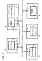
- FIG. 1 is a block diagram showing an example of the system configuration according to a first embodiment of the present invention.
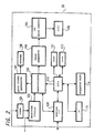
- FIG. 2 is a block diagram showing a structure example of a video receiver.
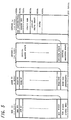
- FIG. 3 is a block diagram showing a structure example of a video equipment.
- FIG. 4 is an explanatory diagram showing a frame structure example prescribed in the IEEE1394 standard.
- FIG. 5 is an explanatory diagram showing a structure example of address space of CSR architecture.
- FIG. 6 is an explanatory diagram showing an example of position, name and function in principal CSR.
- FIG. 7 is an explanatory diagram showing a structure example of plug control registers.
- FIG. 8 is an explanatory diagram showing structure examples of bus info block, route directory, and unit directory.
- FIG. 9 is an explanatory diagram showing structure examples of oMPR, oPCR, iMPR, and iPCR.
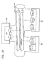
- FIG. 10 is an explanatory diagram showing an example of the relation among plugs, plug control registers, and transmission channels.
- FIG. 11 is an explanatory diagram showing a data structure example according to a hierarchical structure of a descriptor.
- FIG. 12 is an explanatory diagram showing a data structure example of a descritor.
- FIG. 13 is an explanatory diagram showing an example of generation ID in FIG. 12.
- FIG. 14 is an explanatory diagram showing an example of the list ID in FIG. 12.
- FIG. 15 is an explanatory diagram showing a stack model example of the AV/C command.
- FIG. 16 is an explanatory diagram showing an example of the relation between the command and response of the AV/C command.
- FIG. 17 is an explanatory diagram showing in more detail an example of the relation between the command and response of the AV/C command.
- FIG. 18 is an explanatory diagram showing a data structure example of the AV/C command.
- FIG. 19 is an explanatory diagram showing a specific example of the AV/C command.
- FIG. 20 is an explanatory diagram showing a specific example of the command and response of the AV/C command.
- FIG. 21 is an explanatory diagram showing a transmission example of the command according to the first mode for carrying out the present invention.
- FIG. 22 is an explanatory diagram showing a setting example of a preset entry according to the first mode for carrying out the present invention.
- FIG. 23 is an explanatory diagram showing an example of an output preset control command and its response according to the first mode for carrying out the present invention.
- FIG. 24 is an explanatory diagram showing an example of an output preset status command and its response according to the first mode for carrying out the present invention.
- FIG. 25 is an explanatory diagram showing an example of an input select control command and its response according to the first mode for carrying out the present invention.
- FIG. 26 is an explanatory diagram showing an example of an input select status command and its response according to the first mode for carrying out the present invention.
- FIG. 27 is an explanatory diagram showing a use example of the subfunction according to the first mode for carrying out the present invention.
- FIG. 28 is an explanatory diagram showing an example of the system configuration according to the second mode for carrying out the present invention.
- FIG. 29 is an explanatory diagram showing an example of a signal source status command and its response according to the second mode for carrying out the present invention.
- FIG. 30 is an explanatory diagram showing an example (in case of virtual output) of the signal source status command and its response according to the second mode for carrying out the present invention.
- FIG. 31 is a flow chart showing a process example (example 1) of a rec. monitor according to the second mode for carrying out the present invention.
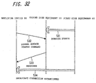
- FIG. 32 is an explanatory diagram showing the process example (example 1) of the rec. monitor according to the second mode for carrying out the present invention.
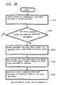
- FIG. 33 is a flow chart showing a process example (example 2) of the rec. monitor according to the second mode for carrying out the present invention.
- FIG. 34 is an explanatory diagram showing the process example (example 2) of the rec. monitor according to the second mode for carrying out the present invention.
- FIG. 1 shows an example in which five AV equipments 10, 20, 30, 40 and 50 are connected through the bus 1.
- the respective equipments connected to the bus 1 have herein terminals for connecting to the IEEE 1394 system bus which connects a first and a second video receivers 10 and 20 with a first, a second and a third video equipments 30, 40 and 50.
- the first and second video receivers 10 and 20 include a monitor subunit 11 and 21 respectively to receive video data inputted from the outside for displaying it on a video display means.
- the first video receiver 10 includes a tuner subunit 12 which can also process to display the received video data.
- the first, second and third video equipments 30, 40 and 50 record an input video data, etc. using a recording medium such as the video tape and reproduce the video data recorded in that medium for outputting.
- each of the equipments 10 to 50 connected to the bus 1 is herein called a unit. Between units, it is possible to mutually read and write information stored in each unit for control, using a descriptor prescribed in AV/C Digital Interface Command Set General Specification (hereinafter referred to as "AV/C") of AV/C Command Transaction Set.
- AV/C Digital Interface Command Set General Specification
- Each function of the unit is called a subunit. Communication between the subunit within each unit and the bus 1 is performed through a plug 13, 22, 32, 42 and 52 that each unit has. In this case, each plug has a plurality of output ports (output plugs) and input ports (input plugs) formed virtually so that communication can be made with a plurality of units simultaneously.
- Each unit connected to the bus 1 is also called a node to which a node ID is given.
- a sender and a receiver of data on the bus is specified by the node ID.
- the first video unit 30 includes an analog output port 33 and the first video receiver unit 10 includes an analog input port 14 in this example.
- the analog output port 33 and the analog input port 14 are connected through an analog signal transmission line 2.
- a signal reproduced from a recording medium at the first video unit 30 is an analog video signal
- this signal is transmitted to the first video receiver unit 10 through the analog signal transmission line 2.
- Data transmitted through the bus 1 such as video data are all digital data.
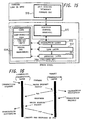
- FIG. 2 is a block diagram showing a structure example of the first video receiver 10.
- Digital broadcast data received through a predetermined channel by a tuner 101 to which an antenna (not shown) is connected are supplied to a receiving circuit 102 for decoding.
- the decoded broadcast data is supplied to a demultiplexer 103 for separating video data from audio data.
- the separated video data is supplied to an image generator 104 for processing to receive an image.
- a CRT drive circuit 105 drives a cathode ray tube (CRT) 106 to make it display the image.
- audio data separated by the demultiplexer 103 is supplied to an audio signal reproducer 107 which performs an audio processing such as conversion to analog and amplification.
- the processed audio signal is supplied to a speaker 108 for outputting.
- the video receiver 10 includes an interface 109 for connecting it to an IEEE1394 type bus.
- Video data and audio data acquired from the IEEE1394 type bus side to the interface 109 are supplied to the demultiplexer 103 for enabling the image to be displayed at CRT 106 and the audio to be outputted from the speaker 108.
- video data and audio data received by the tuner 101 are supplied from the demultiplexer 103 to the interface 109 for transmitting them to the IEEE1394 type bus side.
- an analog video signal and an analog audio signal can be inputted to the receiving circuit 102 from the outside.
- the display processing in the video receiver 10 and the transmission processing through the interface 109 are performed under the control of a central processing unit (CPU) 110.
- CPU central processing unit
- a memory 111 which is a ROM storing a program necessary for control, etc.
- a memory 112 which is a work RAM.
- operating information from an operation panel 114 and control information from a remote control device whose infrared light receiver 115 receives, so that an operation control corresponding to the operating information and control information is performed.
- control data such as command and its response according to the AV/C command stated below through the IEEE1394 type bus
- those data are supplied to the CPU 110 for enabling the CPU 110 to perform the corresponding operation control.
- Transmission of the command and its response from the interface 109 is also performed under the control of the CPU 110.
- Data necessary for the control is stored in the memory 112 and the like connected to the CPU 110.
- Figure 3 is a block diagram showing a structure example of the first video equipment 30 formed as a digital video cassette recorder (DVCR).
- DVCR digital video cassette recorder
- digital broadcast data received through a predetermined channel by a tuner 301 built in the video equipment 30 is supplied to a MPEG (moving Picture Experts Group) encoder 302 which converts them into video data and audio data of a format suitable for recording such as a MPEG2 format.
- MPEG moving Picture Experts Group
- the encoder 302 performs no processing.
- Data encoded by the MPEG encoder 302 is supplied to a record/playback section 303 for record processing and the processed data to be recorded is supplied to a recording head within a rotary head drum 304 for causing the data to be recorded in a magnetic tape within a tape cassette 305.
- Analog video and audio signals inputted from the outside are converted into digital data by an analog/digital converter 306 and then converted into, e.g. MPEG2 type video and audio data by the MPEG encoder 302.
- the resulting data are supplied to the record/ playback section 303 for record processing and the processed data to be recorded are supplied to the recording head within the rotary head drum 304 for causing them to be recorded in the magnetic tape within the tape cassette 305.
- a signal obtained by playing back the magnetic tape within the tape cassette 305 by the rotary head drum 304 is processed to reproduce video and audio data by the record/playback section 303.
- These video and audio data are supplied to the MPEG decoder 307 for decoding, e.g. from the MPEG2 format.
- the decoded data are supplied to a digital/analog converter 308 for converting them into analog video and audio signals which are outputted to the outside.
- the video equipment 30 includes an interface 309 for connecting it to the IEEE1394 type bus.
- Video and audio data inputted from the IEEE1394 type bus side to the interface 309 are supplied to the record/playback section 303 for enabling them to be recorded in the magnetic tape within the tape cassette 305.
- video and audio data reproduced from the magnetic tape within the tape cassette 305 are supplied from the record/playback section 303 to the interface 309 for transmitting them to the IEEE1394 type bus side.
- a format conversion may be performed by a circuit within the video equipment 30.
- the record processing and playback processing within the video equipment 30 as well as the transmission processing through the interface 309 are performed under the control of the central processing unit (CPU) 310, to which a memory 311 that is a work RAM is connected. Further, operating information from an operation panel 312 and control information from a remote control device whose infrared light receiver 313 receives are supplied to the CPU 310, which performs an operation control corresponding to the operating information and control information.
- CPU central processing unit
- control data such as command and its response according to the AV/C command stated below through the IEEE1394 type bus
- those data are supplied to the CPU 310, which is enabled to perform the corresponding operation control.
- the transmission of command and its response from the interface 309 is also performed under the control of the CPU 310.
- Data necessary for the control is stored in the memory 311, etc. connected to the CPU 310.
- structures of the second video receiver 20, the second and third video equipment 40 and 50 are not described herein, but they are basically the same as those of the video receiver 10 and the video equipment 30 shown in Figure 2 and Figure 3.
- FIG. 4 is a diagram showing a cycle structure in data transmission among equipments connected to each other by the IEEE1394 bus.
- data is divided into packets which are transmitted on a timesharing basis in a cycle of 125 ⁇ s as a reference. This cycle is created by a cycle-start signal supplied from a node having a cycle master function (any one of equipments connected to the bus).
- Isochronous packets have a secured bandwidth required for transmission (This is a time length, but is termed a bandwidth) starting from the head of each cycle.
- a bandwidth bandwidth
- Independent channel numbers 0, 1, 2, ⁇ ,63 are given to each isochronous packets (Iso packet) in one communication cycle shown in Figure 4 for enabling to discriminate among a plurality of Iso transmission data.
- Iso packet isochronous packets
- These are isochronous channels, for which sixty-four channels are prepared herein.
- a channel No.63 is a broadcast channel which can be received by any equipment.
- the other channels are channels through which data is transmitted between specific equipments after a connection is established. Additionally, any channel other than the channel No.63 may be used as the broadcast channel.
- a time period from completion of Iso packet communication to the next cycle-start packet is used for an asynchronous packet (Async packet) transmission.
- Async packet asynchronous packet
- the Iso packet transmission is a transmission method in which a reserved bandwidth (the number of channels) in each communication cycle is secured, but no acknowledgment is made from the receiving side.
- the receiving side is caused to return acknowledgment (Ack) data, thereby confirming the transmission status so that a reliable transmission can be performed.
- a predetermined node In order that a predetermined node performs the isochronous transmission, that node must correspond to an isochronous function. Moreover, at least one of nodes which correspond to the isochronous function must have the cycle master function. Furthermore, at least one of nodes connected to the IEEE 1394 serial bus must have the function of an isochronous resource manager.
- each equipment has a node ID in addition to a node unique ID given individually to each equipment.
- This node ID is collected from each equipment under the control of a controller provided on the network, when a bus reset occurs, for example, when a new equipment is connected to the bus 1 or any equipment is separated from the bus 1.
- the IEEE1394 is based on CSR (Control and Status Resister) architecture having a 64 bit address space prescribed in ISO/ IEC13213.
- Figure 5 is a diagram for explaining the structure of the address space of CSR architecture.
- Upper 16 bits are the node ID indicating nodes on each IEEE1394. The remaining 48 bits are used to specify the address space afforded to each node.
- the upper 16 bits are further divided into 10 bits of bus ID and 6 bits of physical ID (node ID in a narrow sense). Since a value in which all the bits are one is used for a special purpose, 1023 buses and 63 nodes can be specified.
- the bus reset occurs, the node ID is given anew.
- the bus reset occurs when there is a change in any constituent equipment connected to the bus 1. For example, when any one equipment connected to the bus 1 is separated, or when it is recognized that new equipment is connected to the bus 1, the bus reset is executed.
- the address space defined by the upper 20 bits is divided into an initial register space used for a register of 2048 bytes peculiar to CSR, a register peculiar to IEEE1394 and the like, an private space, an initial memory space and so on.
- the space defined by the lower 28 bits is used as a configuration ROM, an initial unit space used for a purpose peculiar to the node, a plug control register (PCR) and so on, when the space defined by its upper 20 bits is the initial register space.
- Figure 6 is a diagram for explaining offset addresses, names and functions of principal CSRs.
- An offset in Figure 6 indicates an offset address from FFFFF0000000h address (a number whose end has "h" attached thereto represents the hexadecimal number) at which the initial register space begins.
- a bandwidth available register having the offset of 220h is a register used for assigning the bandwidth and indicates the bandwidth assignable to the isochronous communication. Only a value of a node operating as an isochronous resource manager is made to be valid. Each node has the CSR in Figure 5, but as far as the bandwidth available register is concerned, what is possessed only by the isochronous resource manager is made to be valid. In other words, the bandwidth available register is substantially possessed only by the isochronous resource manager. When no bandwidth is assigned to the isochronous communication, the maximum value is preserved in the bandwidth available register. Each time the bandwidth is assigned, that value diminishes.
- Channels available registers of the offsets 224h to 228h are registers used for assign
- Each bit thereof corresponds to channel No.0 to No.63, respectively. When a bit is zero, the bit indicates that the corresponding channel has already been assigned. Only the channels available register of a node operating as the isochronous resource manager is valid.
- a configuration ROM based on a general ROM format.
- the configuration ROM are arranged a bus info block, a root directory, and a unit directory.
- the node In order to control the input and output of the equipment through an interface, the node has PCR (plug control register) prescribed in IEC1883 between the addresses 900h and 9FFh within the initial unit space in Figure 5. This is such that the concept of plug is substantiated in order to form a signal route theoretically similar to the analog interface.
- Figure 7 is a diagram for explaining the structure of PCR.
- the PCR includes oPCR (output plug control register) representing an output plug and iPCR (input plug control register) representing an input plug.
- the PCR also includes registers of oMPR (output master plug register) and iMPR (input master plug register) for indicating information on the output plug or input plug which is inherent in each equipment.
- Each equipment does not have a plurality of oMPRs and a plurality of iMPRs, but may have a plurality of oPCRs and iPCRs corresponding to each plug depending on the capability of the equipment.
- the PCR shown in Figure 7 has thirty-one oPCRs and iPCRs, respectively. An isochronous data stream is controlled by operating registers corresponding to these plugs.
- Figure 8 is a diagram showing details of the bus info block, the root directory and the unit directory.
- Company ID in the bus info block has an ID number stored therein which indicates a manufacturer of the equipment.
- Chip ID stores a unique ID in the world, which is inherent in that equipment and does not overlap the other equipment.
- a node unique ID which is an identification number inherent in each equipment is created using these company ID and chip ID.
- "00h” is written into the first octet of a unit spec ID of the unit directory of the equipment satisfying the IEC1833; "A0h” is written into the second octed thereof; and “2Dh” is written into the third octed thereof, respectively. Further, into the first octed of a unit switch version is written "01h”, and into LSB (least significant bit) of the third octed is written "1".
- Figure 9 is a diagram showing structures of oMPR, oPCR, iMPR and iPCR.
- Figure 9A shows the structure of oMPR;
- Figure 9B shows the structure of oPCR;
- Figure 9C shows the structure of iMPR;
- Figure 9D shows the structure of iPCR.
- Data rete capability of two bits on the MSB side of oMPR and iMPR stores a code indicating the maximum transmission speed of isochronous data which can be transmitted or received by the equipment.
- Broadcast channel base of the oMPR prescribes a channel number used in a broadcast output. Number of output plugs of five bits on the LSB side of oMPR stores the number of output plugs possessed by that equipment, namely, a value indicating the number of oPCR.
- Persistent extension field and non-persistent extension field are areas which are defined for future extension.
- On-line at MSB of the oPCR and iPCR indicates the use of the plug. Specifically, its value of 1 indicates that the relevant plug is on-line and its value of 0 indicates that it is off-line.
- Each value of broadcast connection counters of the oPCR and iPCR indicates that there is a broadcast connection (1) or that there is no broadcast connection (0).
- Each value of point-to-point connection counters of six bits in the oPCR and iPCR indicates the number of point-to point connections owned by the relevant plug.
- the point-to-point connection means a connection for performing transmission between a specific node and another specific node only.
- Each value of channel numbers having a six-bit width in the OPCR and iPCR indicates an isochronous channel number to which the relevant plug is connected.
- a value of data rate having a two-bit width in the OPCR indicates a real transmission speed of isochronous data packets outputted from the relevant plug.
- a code which is stored in overhead ID having a four-bit width in the oPCR indicates an over bandwidth of isochronous communication.
- a value of payload having ten-bit width in the oPCR represents the maximum value of data contained by the isochronous packets that the relevant plug can handle.
- FIG 10 is a diagram showing the relation among the plug, the plug control register and the isochronous channel.
- equipments connected through the IEEE1394 type bus are shown as AV-devices 901 to 903.
- oPCR[0] to oPCR[2] whose transmission speed and the number of oPCRs are defined by oMPR of the AV-device 903
- oPCR[1] specifies a channel for isochronous data, which is transmitted to a channel #1 of the IEEE1394 serial bus.
- the iMPR of the AV-device 901 defines the transmission speed and the number of iPCR of iPCR[0] and iPCR[1].
- the AV-device 901 reads the isochronous data transmitted to the channel #1 of the IEEE1394 serial bus. Likewise, the AV-device 902 transmits isochronous data to a channel #2 specified by oPCR[0], and the AV-device 901 reads the isochronous data from the channel #2 specified by iPCR[1].
- the AV/C command set defined as commands for controlling equipments connected through the IEEE1394 serial bus is utilized for enabling the control of the equipments, the estimation of their conditions and the like to be performed. This AV/C command set will be described next.
- Figure 11 shows the data structure of the subunit identifier descriptor.
- the subunit identifier descriptor is formed by lists of hierarchical structure. The list represents, for example, a channel which can be received, in case of a tuner, a tune which is recorded therein, in case of a disk, and so on.
- the list on the top layer of the hierarchical structure is termed a root list.
- a list 0 forms a root relative to the lower lists.
- Other lists form the root lists as well.
- the root lists exist as many as the number of objects. In this connection, for example, if an AV-device connected to the bus is a tuner, the object means each channel or the like in digital broadcast. Further, all lists on one layer share common information.
- Figure 12 shows a format of a general subunit identifier descriptor.
- the subunit identifier descriptor has attribute information on functions described therein as its contents.
- a descriptor length field does not include a value of the field itself.
- Generation ID shows a version of the AV/C command set and its value is, e.g.”00h" (h represents that it is hexadecimal).
- "00h” means, as shown in Figure 13 for example, that data structure and command correspond to a version 3.0 in the AV/C General Specification.
- all values except "00h” are reserved for future specification.
- Size of list ID indicates the number of bytes of list ID.
- Size of object ID indicates the number of bytes of object ID.
- Size of object position indicates a position (the number of bytes) in a list used when it is referred to during control operation.
- Number of root object list indicates the number of root object lists.
- Root object list ID shows an ID for identifying the top root object list on the respective independent layers.
- Subunit dependent length indicates the number of bytes in a subsequent subunit dependent information field.
- Subunit dependent information field is a field showing information which is inherent to function.
- Manufacturer dependent length indicates the number of bytes in a subsequent manufacturer dependent information field.
- Manufacturer dependent information field is a field showing information on specification of vendor (manufacturer). Additionally, if there is no manufacturer dependent information in the descriptor, this field will not exist.
- Figure 14 shows assignment ranges of the list ID value shown in Figure 12. As shown in Figure 14, "0000h to 0FFFh” and “4000h to FFFFh” are reserved as assignment ranges for future specification. "1000h to 3FFFh” and "10000h to max list ID value" are prepared for identifying function type dependent information.
- Figure 15 shows a stack model of the AV/C command set.
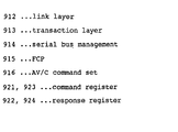
- physical layer 911, link layer 912, transaction layer 913 and serial bus management 914 are based on the IEEE 1394 standard.
- FCR (function control protocol) 915 is based on IEC 61883.
- the AV/C command set 916 is based on 1394TA specification.
- FIG 16 is a diagram for explaining the command and its response of FCP 915 in Figure 15.
- the FCP is a protocol for controlling equipments (nodes) on the IEEE 1394 type bus.
- a controlling side is a controller and a controlled side is a target.
- Command transmission or response of the FCP takes place between nodes using write transaction of asynchronous communication under the IEEE1394.
- the target which has received data returns acknowledgement to the controller for confirming the reception.
- Figure 17 is a diagram for explaining in more detail the relation between the command and its response of FCP shown in Figure 16.
- a node A is connected to a node B through the IEEE1394 bus.
- the node A is a controller and the node B is a target.
- a command register of 512 bytes and a response register of 512 bytes are prepared in both of the node A and node B, respectively.
- the controller transmits instructions to the target by writing a command message into the command register 923 thereof.
- the target responds to the controller by writing a response message into the response register 922 thereof.
- control information is exchanged.
- the kind of the command set transmitted by FCP is described in CTS within a data field of Figure 18, which is described below.
- Figure 18 shows a data structure of a packet transmitted in the asynchronous transmission mode of the AV/C command.
- AV/C command frames and response frames are exchanged between nodes using the FCP. It is arranged that the response to command should be performed within 100ms so as to avoid burdening the bus and AV equipments.
- An upper part of the drawing shows a heater portion of a packet and a lower part of the drawing shows a data block. Destination ID indicates the destination.
- the field of ctype/response indicates a functional classification of the command if the packet is the command, and indicates a processed result of the command if the packet is the response.
- the command is roughly divided into four kinds. They are defined as (1) a command for controlling functions from the outside (CONTROL), (2) a command for inquiring the status from the outside (STATUS), (3) a command for inquiring from the outside whether the control command is supported or not (GENERAL INQUIRY (whether opcode and operands are supported or not)), (4) a command for requiring to notify a change in status to the outside (NOTIFY).
- the response will be returned depending on the kind of command.
- the response to the CONTROL command includes “NOT IMPLEMENTED”, “ACCEPTED”, “REJECTED” and “INTERIM”.
- the response to the STATUS command includes “NOT IMPLEMENTED”, “REJECTED”, “IN TRANSITION” and “STABLE”.
- the response to the command for inquiring from the outside whether the command is supported or not includes “IMPLEMENTED” and "NOT IMPLEMENTED”.
- the response to the command for requiring to notify a change in status to the outside includes “NOT IMPLEMENTED", “REJECTED”, “INTRIM” and "CHANGED”.
- Subunit type is provided to specify functions within the equipments, to which, e.g. tape recorder/player, tuner and the like are assigned.
- BBS bulletin board subunit
- Opcode which is a code of operation represents a command and operand represents a parameter of the commend.
- a field which is added if necessary (additional operands) is also prepared. Following the operands, zero data and the like is added if necessary.
- Data CRC cyclic redundancy check
- Figure 19 shows a specific example of the AV/C command.
- the left side of Figure 19 shows a specific example of command type/ response. The upper part of that portion represents the command and the lower part of that portion represents the response.
- the CONTROL command is assigned to "0000”.
- the STATUS command is assigned to "0001”.
- the SPECIFIC INQUIRY command is assigned to "0010”.
- the NOTIFY command is assigned to "0011”.
- the GENERAL INQUIRY command is assigned to "0100”. "0101 to 0111” are reserved for future specification.
- the NOT IMPLEMENTED response is assigned to "1000”.
- the ACCEPTED response is assigned to "1001”.
- the REJECTED response is assigned to "1010”.
- the IN TRANSITION response is assigned to "1011”.
- the IMPLEMENTED/STABLE response is assigned to "1100”.
- the CHANGED response is assigned to "1101”.
- the INTERIM response is assigned to "1111”. "1110
- FIG. 19 shows specific examples of the subunit types.
- a video monitor is assigned to "00000”.
- a disc recorder/player is assigned to "00011”.
- a tape recorder/player is assigned "00100”.
- a tuner is assigned to "00101”.
- a video camera is assigned to "00111”.
- the BBS used as a bulletin board (bulletin board subunit) is assigned to "01010”.
- a subunit type which is unique to vendor (vendor unique) is assigned to "11100”.
- a specific subunit type is assigned to "11110".
- a unit is assigned to "11111", which is used when destination is an equipment (unit) itself. For example, on/off of power supply and the like can be cited.
- FIG. 19 The right side of Figure 19 shows specific examples of opcodes (operation codes).
- Each subunit type has its own opcode table. Opcodes when the relevant subunit type is a tape recorder/ player are shown in the drawing. The operands are defined in each opcode.
- Figure 20 shows specific examples of the AV/C command and its response.
- Figure 21 is a diagram showing an example of a case where the first video receiver 10 inquires the first video equipment 30 about the preset entry.
- the first video receiver 10 transmits first an output preset control command along the form of AV/C command to the first video equipment 30 (step S11), and acquires data of the preset entry number through a response to that command from the first video equipment 30 (step S12). It is arranged that a control section in the first video equipment 30 manages the preset entry number and therefore processing based on instructions from an equipment which inputs data outputted from the first video equipment 30 can be performed.
- the preset entry number set by the first video equipment 30 is the number which is preset for each equipment so that the first video equipment 30 can output.
- the maximum number of equipments which can simultaneously input data from one equipment 30 corresponds to the maximum value of preset entry number.
- three preset entries of video data can be set for the first video equipment 30.
- three preset entry 1, 2, 3 are set and node IDs of equipments on the output side are stored for the respective preset entry numbers.
- a node ID of the first video receiver 10 is stored for the preset entry number 1 and a node ID of the second video receiver 20 is stored for the preset entry number 2.
- Figure 23 is a diagram showing the structure of the output preset control command (the left side of Figure 23) and the structure of the response to that command (the right side oof Figure 23). Additionally, portions shown by “ ⁇ " in the response indicates portions in which data arranged in the command is returned as it is (The same applies to other drawings described below.).
- the output preset control command will be described first.
- a value of the control command of "output preset” showing that it is the relevant command is transmitted as eight-bit data of opcode.
- data of the preset entry number is arranged in an eight-bit interval of "operand (0)” and "zero” is arranged in one bit at the head of an eight-bit interval of "operand (0)”.
- a value of "0x7F” which is the maximum value in the hexadecimal number represented by seven bits is arranged in the remaining interval.
- a data value to which Ox is attached represents that it is a hexadecimal value such as 0, 1 2, ⁇ 9, A, B, ⁇ E, F). This is the same value as the hexadecimal value shown by attaching h at its end.
- opernd (1) and "operand (2)” is arranged a destination ID which is a node ID of a destination equipment (an equipment forming the input side).
- opernd (3) and “operand (4)” are arranged data on a subunit of the destination equipment (the equipment forming the input side) and data on a subunit plug of the destination equipment as signal destination data.
- a control section within the source equipment stores not only the correspondence between the preset entry number and node ID shown in Figure 22 but also other data indicated by the command. Further, it stores a setting status of the input plug, etc. in the destination equipment receiving data from the source equipment. Then, if the source equipment transmits various control commands after indicating the preset entry number, etc., the destination equipment will be able to instruct directly the source equipment about various operations.
- Figure 24 shows the structure of the output preset status command.
- Figure 24 shows the structure of the output preset status command (the left side of Figure 24) and the structure of the response to the command (the right side of Figure 24).
- the structure of the command will be described below.
- a value of status command of "output preset” showing that it is the relevant command is transmitted as data of "opcode”.
- Data on preset entry number is arranged as a value of "operand (0).
- In "operand (1)” to "operand (4)” are arranged the maximum value of hexadecimal number "0xFF" respectively so as to indicate that it is a field desirable for acquiring a response to the inquiry.
- a node ID of the destination equipment is arranged in "operand (1)” and "operand (2)” interval.
- "operand (3)” and “operand (4)” are arranged data on a subunit of the destination equipment and data on a subunit plug of the destination equipment as a signal destination data. In the other intervals, the command data is returned as it is.
- this output preset status command when a predetermined data such as the maximum value is arranged in "operand (0)" interval for preset entry data of the command, it is designed that the maximum value data of the preset entry number which can be set is transmitted in the corresponding interval of the response in order to indicate how many units can be connected.
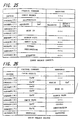
- Figure 25 is a diagram showing the structure of an input select control command (the left side of Figure 25) and the structure of its response (the right side of Figure 25) in this case.
- control command "input select” showing that it is the relevant is transmitted using "opcode” data.
- Data of subfunction is arranged in "operand (0)". This subfunction data has at least two status. One of them corresponds to a case where the input change instructions by the command transmitted at that time is instructions to make the input change perform at once. The other of them corresponds to another case where the input change instructions by command transmitted at that time is instructions to communicate it to the destination equipment that input change is instructed and make the destination equipment wait on stand by without performing the input change.
- the first half four bit portion of "operand (1)” interval is made to be reserved and the second half four bit portion includes the maximum value of hexadecimal number "0xF.
- "operand (2)” and "operand (3)” is arranged node ID data on the output side.
- In “operand (4)” is arranged output plug data of unit.
- In “operand (5)” is arranged input plug data.
- In “operand (6)” and “operand (7)” are arranged data on a subunit of the destination equipment and data on a subunit plug of the destination equipment as signal destination data.
- "Operand (8)" interval is made to be reserved. Additionally, when the maximum value "0xFF" is set for "operand (5)", the target (i.e. an equipment on the receiving side) determines the input plug number and the determined input plug number is returned as response.
- the same data as the command is returned in intervals other than "operand (1).
- "result status" which is data on the status of the destination equipment. For example, when the destination equipment is made to be the first video equipment 30, if the first video equipment 30 is under recording operation of video data and the like, data is arranged which shows that.
- Figure 26 is a diagram showing the structure of the input select status command (the left side of Figure 26) and its response (the right side of Figure 26).
- the first video receiver 10 executes selectively a video data input outputted from the first video equipment 30 and another video data input outputted from the second video equipment 40. Specifically, it is assumed that a playback operation of a recording medium is performed at some moment in the first video equipment 30, and the first video receiver 10 selects an input plug through which its reproduced data is supplied via the bus 1 to cause monitoring the reproduced video data to be started (step S21).
- a playback operation of a recording medium is performed also in the second video equipment 40 while the first video equipment 30 continues to reproduce and the first video receiver 10 is switched so as to select an input plug through which its reproduced data is supplied, so that the monitoring is switched to that of video data from the second video equipment 40 (step S22).
- the video data recorded in the medium which is reproduced by the first video equipment 30 is switched from digital video data to analog video signal.
- the first video equipment 30 must instruct the first video receiver 10 about switching the input plug to the analog input port 14.
- the instructions are transmitted from the first video equipment 30 to the first video receiver 10 as a remote input select control command (step S23).
- This command only requests of the first video receiver 10 to wait on standby without making the corresponding switching (request level).
- the input of the first video receiver 10 is not switched and the monitoring of image from the second video equipment 40 is not disturbed.
- the analog input port 14 is selected instead of the input plug via the bus 1 and the monitoring of video signal from the first video equipment 30 can properly be performed based on data which is switched to the input from the first video equipment 30 by the command of step S23.
- the same processing can also be applied.
- the same processing cam also be applied to a case where a change occurs in the route via the bus 1.
- a serial data bus line (hereinafter merely referred to as bus) according to IEEE1394 standard, which is a digital communication control bus.
- IEEE1394 standard which is a digital communication control bus.
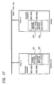
- FIG 28 an example in which three AV equipments 60, 70, 80 are connected through the bus 1 is shown.
- the equipments connected to the bus 1 comprises herein the respective terminals for connecting them to the IEEE1394 type bus, thus making the first and second disk equipments 60, 70 connect to an amplifier device 80.
- the first and second disk equipments 60, 70 include a disk playback subunit 61 and a disk record subunit 71, respectively.
- the former reproduces data from a disk in which audio data and the like are recorded and the latter records inputted audio data and the like in a disk.
- the amplifier device 80 includes an amplifier subunit 81 which performs amplification of the inputted audio data or the like and then supplies the resulting data to a speaker (not shown) for outputting.
- the equipments 60, 70, 80 have plugs 62, 72, 82 for connecting them to the IEEE1394 type bus 1, respectively.
- the communication control processing through the bus 1 can be implemented by comprising an interface for communicating with the IEEE1394 type bus 1, a CPU for controlling the interface, memories for storing control program, etc. and the like in the same way as in case of the equipments 10, 30 described with reference to Figure 2 and Figure 3 showing the first embodiment.
- the plugs 62, 72, 82 included in the respective equipments 60, 70, 80 are also formed by a plurality of imaginary input plugs and a plurality of imaginary output plugs for communicating with a plurality of equipments connected to the bus 1.
- the same processings as described with the first embodiment apply thereto.
- the control between the source equipment and the destination equipment is performed by transmitting various commands described above with the first embodiment.
- a signal source status command is further prepared, thereby allowing the other source equipment to be specified when the source equipment is unable to output.
- Figure 29 is a diagram showing the structure of the signal source status command (the left side of Figure 29) and the structure of its response (the right side of Figure 29). Describing the command structure first, a status command value of "signal source” indicating that it is the relevant command is transmitted as “opcode” data. In “operand (0)” to “operand (2)” are arranged fixed values of "0xFF” indicating that it is a field for acquiring a response to inquiry. In “operand (3)” and “operand (4)” are arranged data on signal destination. This signal destination data indicates an output plug of unit or a destination plug of subunit.
- the virtual output is indicated in the response to this command and also the isochronous channel through which the source equipment inputs and the input plug number of the source equipments are indicated using "operand (1)" and "operand (2)" (step ST13).
- the isochronous channel through which the first disk equipment 60 outputs the data is specified.
- the amplifier device 80 receives through this broadcast channel the output from the first disk equipment 60 (step ST14).
- a mode of receiving data which the equipment 70 inputs herein termed "virtual output”.
- step S32 the status command of signal source requiring to output is transmitted from the amplifier device 80 to the second disk equipment 70 (step S32) after the dubbing from the first disk equipment 60 to the second disk equipment 70 is started at step S31.
- the virtual output is indicated and the broadcast channel is specified as the channel at that time (step S33).
- the amplifier device 80 processes to receive the specified broadcast channel and processes to output the audio data supplied from the first disk equipment 60 (this audio data is the same as what is being recorded in the second disk equipment 70) (step S34).
- audio data reproduced by the first disk equipment 60 is transmitted through the bus 1 to the second disk equipment 70, which starts a dubbing operation to record the data on to the disk (step ST21).
- the amplifier device 80 requires the second disk equipment 70 to supply the audio data outputted therefrom to the amplifier device 80 (step ST22).
- This request may be performed by the signal source command for example.
- the input channel and the imaginary input plug number are transmitted (step ST23). It is here assumed that a channel number other than the broadcast channel is specified as the channel number indicated by this response.
- the amplifier device 80 inquires about an equipment which outputs data inputted to the imaginary input plug number using the input select status command, and decides the outputting equipment (This is herein the first disk equipment 60) by its response (step ST24).
- a point-to point connection is established, which makes a transmission line between the imaginary output plug of the decided equipment on the output side (the first disk equipment 60) and the imaginary input plug of the amplifier device 80 using a specific isochronous channel, thereby causing the amplifier device 80 to receive the output of the first disk equipment 60 (step ST25).
- Figure 34 illustrates the process shown in this flow chart in time sequence. Specifically, it is assumed that the status command of signal source requiring to output is transmitted from the amplifier device 80 to the second disk equipment 70 (step S42) after the dubbing from the first disk equipment 60 to the second disk equipment 70 is started at step S41. In its response on this occasion, the virtual output is indicated (step S43). In this example, because the isochronous channel indicated by this response is a channel other than the broadcast channel, the input select status command is used to inquire about an equipment which outputs data inputted to the imaginary input plug number (step S44) and the outputting equipment (This is herein the first disk equipment 60.) is decided by its response (step S45).
- the amplifier device 80 processes to make a point-to point connection with the first disk equipment 60 established.
- the amplifier device 80 starts inputting audio data outputted from the first disk equipment 60 (step S46).
- each embodiment described above is the example in which data transmission takes place along the AV/C command format within the network formed by the IEEE1394 type bus
- the present invention can be applied to cases where processings are made in a network or format having the other structure.
- the present invention is also applicable to a network which includes a bus line where similar data transmission is performed by radio instead of the bus line which is connected by wire.
- a program for executing each processing described above is retained in some medium and program data obtained from that medium are stored in memories, thereby enabling the communication device capable of the corresponding processing to be achieved.
- a medium of the server for the Internet and the like may be employed in addition to storage media such as a magnetic tape, an optical disk an the like.
Landscapes
- Engineering & Computer Science (AREA)
- Computer Networks & Wireless Communication (AREA)
- Signal Processing (AREA)
- Computer Hardware Design (AREA)
- General Engineering & Computer Science (AREA)
- Multimedia (AREA)
- Selective Calling Equipment (AREA)
- Small-Scale Networks (AREA)
- Details Of Television Systems (AREA)
- Information Transfer Systems (AREA)
Abstract
Description
setting on input selection at a first equipment is instructed from a second equipment through the bus line by a command of a predetermined format.
the instructions about setting on input selection at the first equipment can previously be registered.
when the second equipment desires to input an output of the first equipment, the second equipment inputs a signal from an input signal source which the second equipment specifies by the informed data.
when data outputted from a first equipment can be inputted by a second equipment, data on an output route change of that data from the first equipment is transmitted to the second equipment through the bus line.
the output route includes an output route other than the bus line.
for the data on the output route change, at least two kinds of requests are prepared, a first request instructing the second equipment about input switching to the changed route and a second request not instructing about the input switching, but causing the second equipment to estimate only the route change.
the command instructing about setting on input selection produced by the command producing section is previously sent out from the sending section before the input selection is executed at the other equipment.
the output route indicated by the command produced by the command producing section includes an output route other than the bus line.
for the command on the output route change produced by the command producing section, a command instructing about input switching to the changed route and a command not instructing about the input switching, but deciding only the route change are prepared.
the output route indicated by the command estimated in the data processing section includes an output route other than the bus line.
when the data processing section estimates the command, a processing to switch to inputting data from the changed output route or a processing to only estimate the changed output route is selectively performed by that command.
the program comprises the step of instructing about setting on input selection in a first equipment by means of a predetermined format of command transmitted from a second equipment through the bus line.
the program further comprises the step of causing the instructions about setting on input selection in the first equipment to be registered in advance.
the program comprises the step of informing about the status of input selection in a first equipment connected to the bus line to a second equipment connected to the bus line, so that the second equipment can specify an input signal source to the first equipment.
the program further comprises the step of causing the second equipment to input a signal from the input signal source specified by the second equipment using data informed by the processing at the above informing step.
when data outputted from a first equipment can be inputted by a second equipment, the program comprises the step of causing data on a change of an output route of the data from the first equipment to be transmitted to the second equipment through the bus line.
the output route to be changed in the above step includes an output route other than the bus line.
the processing on a change of the output route in the above step includes two kinds of requests, a request instructing the second equipment at least about input switching to the changed route, and another request not instructing the second equipment about input switching, but only causing the second equipment to estimate the change of route.
Claims (32)
- An equipment control method of performing the control between equipments connected through a predetermined bus line, wherein
setting on input selection at a first equipment is instructed from a second equipment through the bus line by a command of a predetermined format. - An equipment control method according to claim 1, wherein
the instructions about setting on input selection at the first equipment can previously be registered. - An equipment control method of performing the control between equipments connected through a predetermined bus line, whereinthe status of input selection at a first equipment connected to the bus line is informed to a second equipment connected to the bus line, andthe second equipment can specify an input signal source of the first equipment.
- An equipment control method according to claim 3, wherein
when the second equipment desires to input an output of the first equipment, the second equipment inputs a signal from an input signal source which the second equipment specifies by the informed data. - An equipment control method of performing the control between equipments connected through a predetermined bus line, wherein
when data outputted from a first equipment can be inputted by a second equipment, data on an output route change of that data from the first equipment is transmitted to the second equipment through the bus line. - An equipment control method according to claim 5, wherein
the output route includes an output route other than the bus line. - An equipment control method according to claim 5, wherein
for the data on the output route change, at least two kinds of requests are prepared, a first request instructing the second equipment about input switching to the changed route and a second request not instructing about the input switching, but causing the second equipment to estimate only the route change. - An equipment control method of performing the control between equipments connected through a predetermined bus line, whereinat the request of a first equipment, data transmission from a second equipment to the first equipment is instructed, andthe second equipment which receives the instructions about data transmission transmits to the first equipment data on an output port set for the first equipment.
- An equipment control method of performing the control between equipments connected to a predetermined bus line, whereinthe first equipment instructs the second equipment to receive data, andbased on the instructions, the second equipment determines setting on input and transmits data thus set to the first equipment.
- A transmission apparatus capable of data transmission with other equipment connected through a predetermined bus line, comprisinga command producing section for producing a command of a predetermined format to perform setting on input selection at other equipment connected through the bus line, anda sending section for sending the command produced by the command producing section to the bus line.
- A transmission apparatus according to claim 10, wherein
the command instructing about setting on input selection produced by the command producing section is previously sent out from the sending section before the input selection is executed at the other equipment. - A transmission apparatus capable of data transmission with other equipment connected through a predetermined bus line, comprisinga command producing section for producing a command of a predetermined format to inform on the status of input selection to other equipment connected through the bus line, anda sending section for sending out the command produced by the command producing section to the bus line.
- A transmission apparatus capable of data transmission with other equipment connected through a predetermined bus line, comprisingan input section for inputting data transmitted through the bus line, anda data processing section for estimating a command on the status of input selection at other equipment connected through the bus line from the data inputted by the input section and then storing the command.
- A transmission apparatus capable of data transmission with other equipment through a predetermined bus line, comprisinga command producing section for producing a command of a predetermined format instructing other equipment connected through the bus line about an output route change, anda sending section for sending out the command produced by the command producing section to the bus line.
- A transmission apparatus according to claim 14, wherein
the output route indicated by the command produced by the command producing section includes an output route other than the bus line. - A transmission apparatus according to claim 14, wherein
for the command on the output route change produced by the command producing section, a command instructing about input switching to the changed route and a command not instructing about the input switching, but deciding only the route change are prepared. - A transmission apparatus capable of data transmission with other equipment connected through a predetermined bus line, comprisingan input section for inputting data transmitted through the bus line, anda data processing section for estimating and storing a command on the status of output route in other equipment connected through the bus line.
- A transmission apparatus according to claim 17, wherein
the output route indicated by the command estimated in the data processing section includes an output route other than the bus line. - A transmission apparatus according to claim 17, wherein
when the data processing section estimates the command, a processing to switch to inputting data from the changed output route or a processing to only estimate the changed output route is selectively performed by that command. - A transmission apparatus capable of data transmission with other equipment connected through a predetermined bus line, comprisingan input/output section for inputting data transmitted through the bus line and outputting the data to the bus line, anda data processing section for producing, when a command instructing about transmitting data to other equipment connected through the bus line is estimated from the data inputted by the input/output section, a command on a setting status of the input/ output section transmitting the data.
- A transmission apparatus capable of data transmission with other equipment connected through a predetermined bus line, comprisingan input/output section for inputting data transmitted through the bus line and outputting data to the bus line, anda data processing section for producing a command instructing about transmitting data to other equipment connected through the bus line to make the input/output section transmit the command, estimating data on the setting status of output transmitted from the other equipment based on the transmitted command and storing that data.
- A transmission apparatus capable of data transmission with other equipment connected through a predetermined bus line, comprisingan input/output section for inputting data transmitted through the bus line and outputting data to the bus line, anda data processing section which, when a command instructing about receiving data from other equipment connected through the bus line is estimated from the data inputted by the input/output section, produces a command about setting status of the input/output section for receiving data.
- A transmission apparatus capable of data transmission with other equipment connected through a predetermined bus line, comprisingan input/output section for inputting data transmitted through the bus line and outputting data to the bus line, anda data processing section for producing a command instructing other equipment connected through the bus line about receiving data, for transmitting the command from the input/output section, and for estimating data on an input setting status transmitted from the other equipment based on the transmitted command in order to store the data.
- A medium in which a program for performing the control between equipments connected through a predetermined bus line is retained, wherein
the program comprises the step of instructing about setting on input selection in a first equipment by means of a predetermined format of command transmitted from a second equipment through the bus line. - A medium according to claim 24, wherein
the program further comprises the step of causing the instructions about setting on input selection in the first equipment to be registered in advance. - A medium in which a program for performing the control between equipments connected through a predetermined bus line is retained, wherein
the program comprises the step of informing about the status of input selection in a first equipment connected to the bus line to a second equipment connected to the bus line, so that the second equipment can specify an input signal source to the first equipment. - A medium according to claim 26, wherein
the program further comprises the step of causing the second equipment to input a signal from the input signal source specified by the second equipment using data informed by the processing at the above informing step. - A medium in which a program for performing the control between equipments connected through a predetermined bus line, wherein
when data outputted from a first equipment can be inputted by a second equipment, the program comprises the step of causing data on a change of an output route of the data from the first equipment to be transmitted to the second equipment through the bus line. - A medium according to claim 28, wherein
the output route to be changed in the above step includes an output route other than the bus line. - A medium according to claim 28, wherein
the processing on a change of the output route in the above step includes two kinds of requests, a request instructing the second equipment at least about input switching to the changed route, and another request not instructing the second equipment about input switching, but only causing the second equipment to estimate the change of route. - A medium in which a program for performing the control between equipments connected through a predetermined bus line, whereinthe program comprises the steps of sending instructions about transmitting data from a second equipment to a first equipment based on the request from the first equipment, andcausing the second equipment which receives the instructions about transmitting data in the above step to transmit to the first equipment data on an output port arranged for the first equipment.
- A medium in which a program for performing the control between equipments connected through a predetermined bus line, whereinthe program comprises the steps of sending instructions from a first equipment to a second equipment about receiving data, anddetermining setting on input by the second equipment based on the instructions in the above step to cause the set data to be transmitted to the first equipment.
Applications Claiming Priority (3)
| Application Number | Priority Date | Filing Date | Title |
|---|---|---|---|
| JP28345299 | 1999-10-04 | ||
| JP28345299 | 1999-10-04 | ||
| PCT/JP2000/006914 WO2001026295A1 (en) | 1999-10-04 | 2000-10-04 | Method of controlling device, transmission device, and medium |
Publications (2)
| Publication Number | Publication Date |
|---|---|
| EP1137222A1 true EP1137222A1 (en) | 2001-09-26 |
| EP1137222A4 EP1137222A4 (en) | 2005-07-06 |
Family
ID=17665739
Family Applications (1)
| Application Number | Title | Priority Date | Filing Date |
|---|---|---|---|
| EP00964655A Withdrawn EP1137222A4 (en) | 1999-10-04 | 2000-10-04 | DEVICE CONTROL METHOD, TRANSMISSION DEVICE AND MEDIUM ASSOCIATED |
Country Status (7)
| Country | Link |
|---|---|
| US (1) | US6751687B1 (en) |
| EP (1) | EP1137222A4 (en) |
| JP (1) | JP4320993B2 (en) |
| KR (1) | KR100739263B1 (en) |
| CN (1) | CN1174583C (en) |
| AU (1) | AU773294B2 (en) |
| WO (1) | WO2001026295A1 (en) |
Families Citing this family (8)
| Publication number | Priority date | Publication date | Assignee | Title |
|---|---|---|---|---|
| US7068674B1 (en) | 1999-08-23 | 2006-06-27 | Lg Electronics Inc. | Method of controlling connection between nodes in digital interface |
| US20030075983A1 (en) * | 2001-05-03 | 2003-04-24 | Mitsubishi Digital Electronics America, Inc. | Control system and user interface for network of input devices |
| US20020194596A1 (en) * | 2001-06-18 | 2002-12-19 | Srivastava Gopal K. | Control of multiple AV-devices by a single master controller using infrared transmitted commands and bus transmitted commands |
| US6944704B2 (en) * | 2001-10-04 | 2005-09-13 | Sony Corporation | Method and apparatus for utilizing extended AV/C command frames including status inquiry, notify inquiry and control inquiry command types |
| JP3676770B2 (en) * | 2002-09-20 | 2005-07-27 | パイオニア株式会社 | Information transmitting apparatus and information transmitting method |
| US8321650B2 (en) * | 2003-01-13 | 2012-11-27 | Emulex Design & Manufacturing Corporation | Alignment-unit-based virtual formatting methods and devices employing the methods |
| FR2863129A1 (en) * | 2003-11-28 | 2005-06-03 | Thomson Licensing Sa | METHOD FOR MANAGING A TASK WITHIN A NETWORK AND DEVICES FOR PERFORMING SUCH MONITORING |
| FR2895187B1 (en) * | 2005-12-21 | 2010-12-17 | Eastman Kodak Co | MOBILE HOME EQUIPMENT HOSTING STATION AND RESOURCE SHARING METHOD USING THE STATION |
Family Cites Families (8)
| Publication number | Priority date | Publication date | Assignee | Title |
|---|---|---|---|---|
| US4959810A (en) * | 1987-10-14 | 1990-09-25 | Universal Electronics, Inc. | Universal remote control device |
| JP3520572B2 (en) * | 1994-08-02 | 2004-04-19 | ソニー株式会社 | Input device selection method |
| US5715475A (en) * | 1994-12-29 | 1998-02-03 | Intel Corporation | Topological identification and initialization of a system for processing video information |
| US6314479B1 (en) * | 1997-08-04 | 2001-11-06 | Compaq Computer Corporation | Universal multi-pin plug and display connector for standardizing signals transmitted between a computer and a display for a PC theatre interconnectivity system |
| JP4078691B2 (en) | 1997-09-19 | 2008-04-23 | ソニー株式会社 | Recording / reproducing control system, recording / reproducing control method, and recording / reproducing control apparatus |
| WO1999016282A1 (en) * | 1997-09-25 | 1999-04-01 | Mitsubishi Denki Kabushiki Kaisha | Remote control device |
| JPH11150788A (en) * | 1997-11-14 | 1999-06-02 | Yamaha Corp | Audio system |
| JPH11205313A (en) * | 1998-01-08 | 1999-07-30 | Toshiba Corp | Network device and network display method |
-
2000
- 2000-10-04 EP EP00964655A patent/EP1137222A4/en not_active Withdrawn
- 2000-10-04 KR KR1020017006910A patent/KR100739263B1/en not_active Expired - Fee Related
- 2000-10-04 CN CNB008026602A patent/CN1174583C/en not_active Expired - Fee Related
- 2000-10-04 JP JP2001529138A patent/JP4320993B2/en not_active Expired - Fee Related
- 2000-10-04 AU AU75562/00A patent/AU773294B2/en not_active Ceased
- 2000-10-04 US US09/857,279 patent/US6751687B1/en not_active Expired - Fee Related
- 2000-10-04 WO PCT/JP2000/006914 patent/WO2001026295A1/en not_active Ceased
Also Published As
| Publication number | Publication date |
|---|---|
| JP4320993B2 (en) | 2009-08-26 |
| EP1137222A4 (en) | 2005-07-06 |
| KR20010087408A (en) | 2001-09-15 |
| AU7556200A (en) | 2001-05-10 |
| WO2001026295A1 (en) | 2001-04-12 |
| AU773294B2 (en) | 2004-05-20 |
| US6751687B1 (en) | 2004-06-15 |
| KR100739263B1 (en) | 2007-07-12 |
| CN1337112A (en) | 2002-02-20 |
| CN1174583C (en) | 2004-11-03 |
Similar Documents
| Publication | Publication Date | Title |
|---|---|---|
| US20020085088A1 (en) | Information processor and method for processing information | |
| US6751687B1 (en) | Method of controlling device, transmission device, and medium | |
| EP1098476A1 (en) | Network connection recognizing method and network-connected terminal device | |
| US20020046311A1 (en) | Communications controlling method, communications system, and communications device | |
| WO2000070841A1 (en) | Communication method, communication device, communication system and providing medium | |
| US20010024445A1 (en) | Communication system, communication device and communication method | |
| KR20010071380A (en) | Electronic device and its repairing method | |
| JPWO2001026295A1 (en) | Equipment control method, transmission device and medium | |
| JP4419539B2 (en) | Electronic device and communication control method | |
| JP4320955B2 (en) | Information processing method, information processing system, and information processing apparatus | |
| EP1113624A1 (en) | Communication method, communication device, and communication system | |
| US20020041602A1 (en) | Communication control method, communication system, and communication apparatus | |
| JPWO2000069121A1 (en) | Information processing method, information processing system, and information processing device | |
| JP4082237B2 (en) | Communication method and communication apparatus | |
| JP4635290B2 (en) | Control method and display device | |
| EP1109357A1 (en) | Method of communication, communication device, communication controller, communication system, and medium | |
| EP1098475A1 (en) | Network connection recognition method, network system and network connection terminal device | |
| JP2003078537A (en) | Device recognition method and electronic device | |
| JP2002051056A (en) | Communication control method, communication system and communication device | |
| JP2002051054A (en) | Communication control method, communication system and communication device | |
| JPWO2000072519A1 (en) | Communication method, communication device, and communication system | |
| JPWO2000069122A1 (en) | Network connection recognition method, network system and network connection terminal device | |
| WO2000072551A1 (en) | Communication method, communication system and electronic device | |
| JPWO2000069123A1 (en) | Network connection recognition method and network connection terminal device | |
| MXPA01000270A (en) | Network connection recognizing method and network-connected terminal device |
Legal Events
| Date | Code | Title | Description |
|---|---|---|---|
| PUAI | Public reference made under article 153(3) epc to a published international application that has entered the european phase |
Free format text: ORIGINAL CODE: 0009012 |
|
| 17P | Request for examination filed |
Effective date: 20010615 |
|
| AK | Designated contracting states |
Kind code of ref document: A1 Designated state(s): AT BE CH CY DE DK ES FI FR GB GR IE IT LI LU MC NL PT SE |
|
| RBV | Designated contracting states (corrected) |
Designated state(s): DE FR GB |
|
| A4 | Supplementary search report drawn up and despatched |
Effective date: 20050520 |
|
| RIC1 | Information provided on ipc code assigned before grant |
Ipc: 7H 04N 5/77 B Ipc: 7H 04L 12/40 A |
|
| 17Q | First examination report despatched |
Effective date: 20080214 |
|
| STAA | Information on the status of an ep patent application or granted ep patent |
Free format text: STATUS: THE APPLICATION IS DEEMED TO BE WITHDRAWN |
|
| 18D | Application deemed to be withdrawn |
Effective date: 20080625 |