EP1136821B1 - Procédé d'évaluation de résilience d'un assemblage soudé et appareils d'analyse correspondant mesurant de vitesse d'ondes ultrasonores superficielles - Google Patents
Procédé d'évaluation de résilience d'un assemblage soudé et appareils d'analyse correspondant mesurant de vitesse d'ondes ultrasonores superficielles Download PDFInfo
- Publication number
- EP1136821B1 EP1136821B1 EP01400739A EP01400739A EP1136821B1 EP 1136821 B1 EP1136821 B1 EP 1136821B1 EP 01400739 A EP01400739 A EP 01400739A EP 01400739 A EP01400739 A EP 01400739A EP 1136821 B1 EP1136821 B1 EP 1136821B1
- Authority
- EP
- European Patent Office
- Prior art keywords
- waves
- welded assembly
- velocities
- measuring
- head
- Prior art date
- Legal status (The legal status is an assumption and is not a legal conclusion. Google has not performed a legal analysis and makes no representation as to the accuracy of the status listed.)
- Expired - Lifetime
Links
- 238000000034 method Methods 0.000 title claims description 16
- 238000011156 evaluation Methods 0.000 title description 2
- 239000000758 substrate Substances 0.000 claims description 29
- 238000012360 testing method Methods 0.000 claims description 19
- 238000003466 welding Methods 0.000 claims description 10
- 238000005314 correlation function Methods 0.000 claims description 4
- 238000009792 diffusion process Methods 0.000 claims description 4
- 239000000463 material Substances 0.000 claims description 4
- 230000007246 mechanism Effects 0.000 claims description 2
- 238000005259 measurement Methods 0.000 description 8
- 238000002604 ultrasonography Methods 0.000 description 8
- 238000002592 echocardiography Methods 0.000 description 7
- 239000007788 liquid Substances 0.000 description 4
- 230000000712 assembly Effects 0.000 description 3
- 238000000429 assembly Methods 0.000 description 3
- 230000002596 correlated effect Effects 0.000 description 3
- 230000000875 corresponding effect Effects 0.000 description 3
- 229910052751 metal Inorganic materials 0.000 description 3
- 239000002184 metal Substances 0.000 description 3
- 239000000203 mixture Substances 0.000 description 3
- 241001494479 Pecora Species 0.000 description 2
- 238000006243 chemical reaction Methods 0.000 description 2
- 230000001066 destructive effect Effects 0.000 description 2
- XLYOFNOQVPJJNP-UHFFFAOYSA-N water Substances O XLYOFNOQVPJJNP-UHFFFAOYSA-N 0.000 description 2
- 229910001069 Ti alloy Inorganic materials 0.000 description 1
- 230000009286 beneficial effect Effects 0.000 description 1
- 230000000903 blocking effect Effects 0.000 description 1
- 238000004364 calculation method Methods 0.000 description 1
- 230000001276 controlling effect Effects 0.000 description 1
- 238000013461 design Methods 0.000 description 1
- 230000002349 favourable effect Effects 0.000 description 1
- 238000010030 laminating Methods 0.000 description 1
- 238000004519 manufacturing process Methods 0.000 description 1
- 238000011326 mechanical measurement Methods 0.000 description 1
- 238000002844 melting Methods 0.000 description 1
- 230000008018 melting Effects 0.000 description 1
- 230000000149 penetrating effect Effects 0.000 description 1
- 238000011160 research Methods 0.000 description 1
- 238000005096 rolling process Methods 0.000 description 1
- 239000007787 solid Substances 0.000 description 1
- 239000000725 suspension Substances 0.000 description 1
Images
Classifications
-
- G—PHYSICS
- G01—MEASURING; TESTING
- G01N—INVESTIGATING OR ANALYSING MATERIALS BY DETERMINING THEIR CHEMICAL OR PHYSICAL PROPERTIES
- G01N29/00—Investigating or analysing materials by the use of ultrasonic, sonic or infrasonic waves; Visualisation of the interior of objects by transmitting ultrasonic or sonic waves through the object
- G01N29/34—Generating the ultrasonic, sonic or infrasonic waves, e.g. electronic circuits specially adapted therefor
- G01N29/348—Generating the ultrasonic, sonic or infrasonic waves, e.g. electronic circuits specially adapted therefor with frequency characteristics, e.g. single frequency signals, chirp signals
-
- G—PHYSICS
- G01—MEASURING; TESTING
- G01N—INVESTIGATING OR ANALYSING MATERIALS BY DETERMINING THEIR CHEMICAL OR PHYSICAL PROPERTIES
- G01N29/00—Investigating or analysing materials by the use of ultrasonic, sonic or infrasonic waves; Visualisation of the interior of objects by transmitting ultrasonic or sonic waves through the object
- G01N29/04—Analysing solids
- G01N29/07—Analysing solids by measuring propagation velocity or propagation time of acoustic waves
-
- G—PHYSICS
- G01—MEASURING; TESTING
- G01N—INVESTIGATING OR ANALYSING MATERIALS BY DETERMINING THEIR CHEMICAL OR PHYSICAL PROPERTIES
- G01N29/00—Investigating or analysing materials by the use of ultrasonic, sonic or infrasonic waves; Visualisation of the interior of objects by transmitting ultrasonic or sonic waves through the object
- G01N29/22—Details, e.g. general constructional or apparatus details
- G01N29/223—Supports, positioning or alignment in fixed situation
-
- G—PHYSICS
- G01—MEASURING; TESTING
- G01N—INVESTIGATING OR ANALYSING MATERIALS BY DETERMINING THEIR CHEMICAL OR PHYSICAL PROPERTIES
- G01N2291/00—Indexing codes associated with group G01N29/00
- G01N2291/02—Indexing codes associated with the analysed material
- G01N2291/023—Solids
- G01N2291/0231—Composite or layered materials
-
- G—PHYSICS
- G01—MEASURING; TESTING
- G01N—INVESTIGATING OR ANALYSING MATERIALS BY DETERMINING THEIR CHEMICAL OR PHYSICAL PROPERTIES
- G01N2291/00—Indexing codes associated with group G01N29/00
- G01N2291/04—Wave modes and trajectories
- G01N2291/042—Wave modes
- G01N2291/0422—Shear waves, transverse waves, horizontally polarised waves
-
- G—PHYSICS
- G01—MEASURING; TESTING
- G01N—INVESTIGATING OR ANALYSING MATERIALS BY DETERMINING THEIR CHEMICAL OR PHYSICAL PROPERTIES
- G01N2291/00—Indexing codes associated with group G01N29/00
- G01N2291/04—Wave modes and trajectories
- G01N2291/044—Internal reflections (echoes), e.g. on walls or defects
-
- G—PHYSICS
- G01—MEASURING; TESTING
- G01N—INVESTIGATING OR ANALYSING MATERIALS BY DETERMINING THEIR CHEMICAL OR PHYSICAL PROPERTIES
- G01N2291/00—Indexing codes associated with group G01N29/00
- G01N2291/04—Wave modes and trajectories
- G01N2291/057—Angular incidence, parallel to surface propagation
-
- G—PHYSICS
- G01—MEASURING; TESTING
- G01N—INVESTIGATING OR ANALYSING MATERIALS BY DETERMINING THEIR CHEMICAL OR PHYSICAL PROPERTIES
- G01N2291/00—Indexing codes associated with group G01N29/00
- G01N2291/10—Number of transducers
- G01N2291/102—Number of transducers one emitter, one receiver
-
- G—PHYSICS
- G01—MEASURING; TESTING
- G01N—INVESTIGATING OR ANALYSING MATERIALS BY DETERMINING THEIR CHEMICAL OR PHYSICAL PROPERTIES
- G01N2291/00—Indexing codes associated with group G01N29/00
- G01N2291/10—Number of transducers
- G01N2291/103—Number of transducers one emitter, two or more receivers
-
- G—PHYSICS
- G01—MEASURING; TESTING
- G01N—INVESTIGATING OR ANALYSING MATERIALS BY DETERMINING THEIR CHEMICAL OR PHYSICAL PROPERTIES
- G01N2291/00—Indexing codes associated with group G01N29/00
- G01N2291/26—Scanned objects
- G01N2291/267—Welds
Definitions
- the subject of the invention is a method assessment of the resilience of a welded joint, as well that a measuring device suitable for this process and assigned to the measurement of ultrasonic wave velocities superficial.
- the resilience of a mechanical part is the energy it takes to break it. She can be evaluated by tests carried out on test pieces representative of the assembly and respecting certain standards in specialized devices like sheep of Charpy. Obviously the manufacturing and the use of a machine are binding and that other easier methods for use, and in particular non-destructive checks by which resilience would be assessed indirectly would be beneficial.
- the ultrasonic tests are carried out normally after immersing the part to be analyzed in a liquid. Ultrasound is emitted into the liquid towards the part, and it can be reflected or absorbed by it when it reaches it. They can also, for certain favorable incidences, undergo a propagation mode conversion and propagate on the surface of the part, without penetrating beyond a shallow depth, by giving surface waves called Rayleigh waves.
- An example of the use of ultrasonic waves for controlling welding operation by means of an inclined emission head and an inclined reception head with an inclination opposite to that of the emission head is given by US-A 5,920,014. According to this method, during welding, the instant when the melting temperature is reached is determined and the volume of the weld joint is determined as a function of the duration of the welding.
- the invention is a process for evaluating the resilience of a welded joint obtained by diffusion welding a substrate on a sheet, characterized in that it consists in producing waves surface ultrasound on the substrate, to measure a speed of said waves and then to deduce a parameter speed, and to deduce the resilience of the assembly from a correlation function, obtained previously on calibration specimens comprising a similar welded joint, which connects the resilience of the calibration specimens to the parameter of speed of calibration specimens.
- the speed parameter should rather be deduced from the one of the two speeds which is the slowest.
- This parameter can be a difference in wave speed ultrasonic measured on the sheet of the welded joint and on a reference piece made on the subject of sheet metal base but without welded connection or on the same sheet at two frequencies 1 MHz and 5 MHz. he then the speeds at which the calculation are measured under the same conditions, that is, they relate to the same direction of measurement on the sheet of the welded joint and the sheet of the reference part.
- Another aspect of the invention is a measuring device suitable for this method; it's about an ultrasonic wave speed measuring device of surface on a part, comprising a head of emission of waves directed towards the part but with a tilt, and a second head, assigned either to collect a portion waves broadcast from the room, either to send back the said portion towards the emission head in an echo, the second head being directed towards the room but with a tilt opposite to the tilt of the head emission, characterized in that the second head comprises two active faces, charged to collect or return said portion of the waves, arranged in tiers and at an identical distance from the room.
- the frame includes a frame and support mechanisms for the heads on the frame which are designed to allow adjustment of heads tilt
- Another aspect of the invention is an apparatus according to the claim 9, or active surfaces are cylindrical with parallel axes and of the same radius, with a second head orthogonal to the surface of the part.
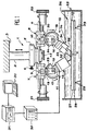
- the machine used includes a frame 1 can be composed of a vertical column 2 of suspension at a fixed point 3 and a slide 4 connected to column 2 via a slide 5 can be fixed at a specific location of column 2 by a pressure screw 6.
- Two sliders 7 and 8 are placed on opposite sides of the slide 4 and can be held in place by pressure screws-9 and 10. They each carry a head assigned to the measurement, of respective reference 11 and 12 and whose essential element is an ultrasonic sensor 13 for the first and a reflector 14 for the second.
- the heads 11 and 12 are mounted on the sliders 7 and 8 by horizontal pivots 15 and 16, parallel to each other and perpendicular to the direction of slide 4, and they are provided with sectors teeth 17 and 18 forming racks meshing with worms 19 and 20 operated by handles 21 and 22 set on sliders 7 and 8 of so that heads 11 and 12 can be brought to selected slopes, but opposite one to the other in the measurements so that the sensor 13 and the reflector 14 are directed in directions descending and converging.
- Other fixing screws 23 and 24 for blocking heads 11 and 12 on the sliders 7 and 8 allow to prohibit rotations involuntary toothed sectors 17 and 18 compared at sliders 7 and 8 when the desired tilt has been reached.
- a flywheel 43 placed under the slide 5 rotates the slide 4 in a plane horizontal.
- the senor 13 is responsible for both emitting ultrasound and collect echoes, as is common in this technique, and the reflector 14 is responsible for produce these echoes; however, it would be possible to replace the reflector 14 with a pair of sensors the way that will be described later without the principle be changed.
- the machine overlooks a measuring tank 25 partially filled with water, so that the sensor 13 and the reflector 14 are partially submerged and that the ultrasonic waves used do not leave the liquid;
- the machine study part is a welded assembly 26, composed of a rather thin sheet 28 and a substrate 27 which can be another sheet or a thicker part placed above, facing the sensor 13 and to the reflector 14 ,.
- the welded joint 26 is installed on blocks 29 at the bottom of the tank 25.
- the sensor 13 is connected to a console control 30 via an oscilloscope 31 responsible for displaying the results and a generator of pulses 32.
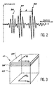
- the sensor 13 emits a wave ultrasound obliquely in the water until it reaches the substrate 27. If the inclination ⁇ of the head 11 and the direction of the waves is well chosen (about 30 °), the wave is transmitted to the substrate 27 under shape of a localized Rayleigh surface wave on the upper face of the substrate 27 and at a low depth, which however reaches the weld between the substrate 27 and sheet metal 28.
- the wave goes towards the edge of substrate 27, but some of it diffuses however upwards, at the inclination corresponding to the value ⁇ given above, and symmetrically to the direction of incidence of the waves relative to the vertical.
- the reflector 14 is composed of two prisms 33 and 34 including the lower surfaces 35 and 36, facing the substrate 27, reflect the ultrasound. If these surfaces are perpendicular to the direction of diffusion of the surface wave towards the high, the wave portion thus diffused is returned in echo by the prisms 33 and 34 towards the substrate 27, before forming a Rayleigh surface wave of return part of which is broadcast according to the same principle towards sensor 13.
- the wave paths are absolutely identical for the round trip. So, the sensor 13 records two echoes corresponding to wave reflections on reflective surfaces 35 and 36, and these echoes are distant from time t necessary for the wave to travel twice the distance X (outward and return) separating the locations of substrate 27 where wave portions are broadcast to these surfaces 35 and 36.
- the two echoes bear the references 37 and 38 on the reading provided by oscilloscope 31 and shown in Figure 2. They can be identified easily since they are similar; other echoes tel 39, produced by a reflection of the wave on the edge 40 of the substrate 27, and which can return to the sensor 13 before the previous ones because of the higher speed of the wave in solids, can also be observed but are useless for the process.
- test pieces like that (41) that Figure 3 illustrates. It consists of a substrate 27 'similar to substrate 27 (i.e. similarly thickness, of the same composition and made of the same way), of a sheet 28 'similar to sheet 28 by the composition and a lower layer 42 formed of the base material of the substrate 27 (or 27 ′), that is to say that it has the same composition and was made from same way while being much thicker. She is welded to the face of the sheet 28 'which is opposite to the substrate 27 '.
- test pieces 41 placed under the machine the place of the welded assembly 26 allow to measure successively the speeds V1 and Vt of the ultrasound of surface in the two main directions, longitudinal and transverse, from substrate 27 ', then the corresponding velocities V10 and Vt0 of the layer lower 42 after having turned the test piece 41.
- the main directions are governed by the direction of laminating the substrate 27 '. Indeed, the rolling produced an anisotropy in the sheets and therefore differences fairly sensitive between V1 and Vt or V10 and Vt0.
- the values V1 and Vt are influenced by the welding performed between 27 'and 28', while the values V10 and Vt0 express the intrinsic properties of matter base of the lower layer 42, the thickness of which is too large for the waves to penetrate to the welding with 28 'sheet.
- An identical result is obtained by making the measurement at higher frequency (5MHz) successively of the speeds V1 and Vt of surface ultrasound in both directions main longitudinal and transverse, of the substrate 27 'We find at this frequency of 5MHz speed values identical to V10 and Vt0 expressing the intrinsic properties of matter.
- 5MHz 5MHz
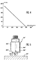
- FIG. 4 shows a linear correlation found between the difference in slow speeds ⁇ V (in m / s) defined above and the resilience R (in J / cm 2 ) for welded joints of sheets of titanium alloys.
- the process allows measurements to be taken in several places of the welded assembly, and therefore to estimate the regularity of it.
Landscapes
- Physics & Mathematics (AREA)
- Health & Medical Sciences (AREA)
- Life Sciences & Earth Sciences (AREA)
- Chemical & Material Sciences (AREA)
- Analytical Chemistry (AREA)
- Biochemistry (AREA)
- General Health & Medical Sciences (AREA)
- General Physics & Mathematics (AREA)
- Immunology (AREA)
- Pathology (AREA)
- Acoustics & Sound (AREA)
- Investigating Or Analyzing Materials By The Use Of Ultrasonic Waves (AREA)
Description
Selon ce procédé, en cours de soudage, l'instant où la température de fusion est atteinte est déterminé et le volume du joint de soudure est déterminé en fonction de la durée du soudage. Les recherches des inventeurs ont montré que ces ondes de surface pouvaient être corrélées à la qualité de soudure des assemblages définis plus haut, et plus précisément qu'un paramètre lié à la vitesse de propagation de ces ondes dans ces assemblages pouvait être corrélé à leur résilience, la soudure affectant la propagation des ondes et ce paramètre en fonction de sa qualité.
- la figure 1 est une vue générale de la machine utilisée,
- la figure 2 est une vue d'un relevé de mesures,
- la figure 3 représente une pièce de référence ou une éprouvette,
- la figure 4 est un exemple concret de fonction de corrélation obtenue,
- et la figure 5 illustre un perfectionnement à la machine.
Claims (9)
- Procédé d'évaluation de résilience d'un assemblage soudé (26) obtenu par soudage-diffusion d'un substrat (27) sur une tôle (28), qui consiste à produire des ondes ultrasonores de surface sur le substrat (27), à mesurer une vitesse desdites ondes puis à en déduire un paramètre de vitesse (ΔV), et à déduire la résilience de l'assemblage d'après une fonction de corrélation, obtenue antérieurement sur des éprouvettes comprenant un assemblage soudé similaire, qui relie la résilience des éprouvettes au paramètre de vitesse des éprouvettes.
- Procédé d'évaluation de résilience d'un assemblage soudé selon la revendication 1, caractérisé en ce qu'il consiste à mesurer deux vitesses (Vl, Vt) desdites ondes sur l'assemblage soudé (26), dans deux directions principales du substrat (27).
- Procédé d'évaluation de résilience d'un assemblage soudé selon la revendication 2, caractérisé en ce que le paramètre de vitesse est déduit de celle des deux vitesses qui est la plus lente.
- Procédé d'évaluation de résilience d'un assemblage soudé selon l'une quelconque des revendications 1 à 3, caractérisé en ce que le paramètre de vitesse est une différence de vitesse des ondes ultrasonores de surface sur la tôle de l'assemblage soudé et sur une pièce faite (42) en matière de base de la tôle ou sur la même tôle à deux fréquences 1MHz et 5MHz.
- Procédé d'évaluation de résilience d'un assemblage soudé selon les revendications 3 et 4, caractérisé en ce que la différence des vitesses est calculée pour celle des deux vitesses qui est la plus lente sur l'assemblage soudé et celle de deux vitesses, mesurées dans deux directions principales de la pièce faite en matière de base de la tôle, qui est la plus lente.
- Appareil de mesure de vitesse d'ondes ultrasonores de surface sur une pièce, comprenant une tête d'émission (11) des ondes dirigée vers la pièce mais avec une inclinaison, et une seconde tête (12), affectée soit à recueillir une portion des ondes diffusée de la pièce, soit à renvoyer ladite portion vers la tête d'émission en un écho, la seconde tête étant dirigée vers la pièce mais avec une inclinaison opposée à l'inclinaison de la tête d'émission et comprenant deux faces actives (35, 36), chargées de recueillir ou de renvoyer ladite portion des ondes, disposées en gradins et à une distance identique de la pièce.
- Appareil de mesure de vitesse d'ondes ultrasonores de surface selon la revendication 6, caractérisé en ce qu'il comprend un bâti et des mécanismes de support (4, 17, 18, 19, 20, 21, 22) des têtes sur le bâti, conçus de manière à permettre de régler les inclinaisons des têtes.
- Appareil de mesure de vitesses d'ondes ultrasonores de surface selon l'une des revendications 6 ou 7, caractérisé en ce que les têtes (11, 12) sont montées sur un support (4, 5, 43) pivotant dans un plan horizontal.
- Appareil de mesure de vitesses d'ondes ultrasonores de surface sur une pièce, comprenant une tête d'émission des ondes dirigée vers la pièce mais avec une inclinaison et une second a tête (12'), affectée soit à recueillir une portion des ondes diffusée de la pièce, soit à renroyer ladite portion vers la tête d'émission en un écho, la seconde tête (12') étant placée orthogonalement à la surface de pièce (27) et comprenant deux faces actives (35',36'), chargées de recueillir ou de renvoyer ladite portion des ondes et qui sont cylindriques, aux axes parallèles et de même rayon.
Applications Claiming Priority (2)
| Application Number | Priority Date | Filing Date | Title |
|---|---|---|---|
| FR0003696 | 2000-03-23 | ||
| FR0003696A FR2806801B1 (fr) | 2000-03-23 | 2000-03-23 | Procede d'evaluation de resilience d'un assemblage soude et appareil d'analyse correspondant mesurant des vitesses d'ondes ultrasonores superficielles |
Publications (2)
| Publication Number | Publication Date |
|---|---|
| EP1136821A1 EP1136821A1 (fr) | 2001-09-26 |
| EP1136821B1 true EP1136821B1 (fr) | 2003-07-02 |
Family
ID=8848411
Family Applications (1)
| Application Number | Title | Priority Date | Filing Date |
|---|---|---|---|
| EP01400739A Expired - Lifetime EP1136821B1 (fr) | 2000-03-23 | 2001-03-22 | Procédé d'évaluation de résilience d'un assemblage soudé et appareils d'analyse correspondant mesurant de vitesse d'ondes ultrasonores superficielles |
Country Status (10)
| Country | Link |
|---|---|
| US (1) | US6681632B2 (fr) |
| EP (1) | EP1136821B1 (fr) |
| JP (1) | JP4160755B2 (fr) |
| CA (1) | CA2374218C (fr) |
| DE (1) | DE60100410T2 (fr) |
| ES (1) | ES2195981T3 (fr) |
| FR (1) | FR2806801B1 (fr) |
| RU (1) | RU2249815C2 (fr) |
| UA (1) | UA72515C2 (fr) |
| WO (1) | WO2001071339A1 (fr) |
Families Citing this family (5)
| Publication number | Priority date | Publication date | Assignee | Title |
|---|---|---|---|---|
| JP5448870B2 (ja) * | 2009-04-23 | 2014-03-19 | ルネサスエレクトロニクス株式会社 | Pll回路 |
| FR2999714B1 (fr) * | 2012-12-17 | 2016-01-15 | Snecma | Procede de caracterisation d'une piece en materiau composite |
| US10352906B2 (en) * | 2016-12-15 | 2019-07-16 | Bell Helicopter Textron Inc. | Through-transmission ultrasonic testing apparatus |
| CN211491186U (zh) * | 2019-12-20 | 2020-09-15 | 江苏科泰检测技术服务有限公司 | 焊缝检测定位夹具 |
| RU2760634C1 (ru) * | 2020-11-03 | 2021-11-29 | Федеральное государственное бюджетное учреждение науки Институт физики металлов имени М.Н. Михеева Уральского отделения Российской академии наук (ИФМ УрО РАН) | Способ оценки ударной вязкости изделий из закаленной на бейнит конструкционной стали |
Family Cites Families (16)
| Publication number | Priority date | Publication date | Assignee | Title |
|---|---|---|---|---|
| US3850028A (en) * | 1972-11-16 | 1974-11-26 | Rockwell International Corp | Method for ultrasonic inspection |
| US3868847A (en) * | 1972-12-04 | 1975-03-04 | Walter A Gunkel | System and apparatus for inspecting elongated welds |
| US4144766A (en) * | 1977-05-02 | 1979-03-20 | The Babcock & Wilcox Company | Apparatus for the in-situ detection and location of flaws in welds |
| US4372163A (en) * | 1981-02-03 | 1983-02-08 | Rockwell International Corporation | Acoustic measurement of near surface property gradients |
| SU1298657A1 (ru) * | 1985-12-02 | 1987-03-23 | Опытное конструкторско-технологическое бюро "Феррит" при Воронежском политехническом институте | Устройство дл ультразвукового контрол поверхности материала |
| US5085082A (en) * | 1990-10-24 | 1992-02-04 | The Babcock & Wilcox Company | Apparatus and method of discriminating flaw depths in the inspection of tubular products |
| US5408882A (en) * | 1991-06-24 | 1995-04-25 | General Electric Company | Ultrasonic device and method for non-destructive evaluation of polymer composites |
| DE4325878C2 (de) * | 1992-07-31 | 1995-07-06 | Fraunhofer Ges Forschung | Verfahren zur Bewertung von Widerstandsschweißverbindungen |
| CA2144597C (fr) * | 1994-03-18 | 1999-08-10 | Paul J. Latimer | Sonde amelioree a transducteur acoustique electromagnetique (emat) et technique pour l'inspection de soudures |
| US5439157A (en) * | 1994-07-18 | 1995-08-08 | The Babcock & Wilcox Company | Automated butt weld inspection system |
| US5474225A (en) * | 1994-07-18 | 1995-12-12 | The Babcock & Wilcox Company | Automated method for butt weld inspection and defect diagnosis |
| US5537876A (en) * | 1994-08-02 | 1996-07-23 | Davidson; Paul K. | Apparatus and method for nondestructive evaluation of butt welds |
| DE19612925C1 (de) * | 1996-04-01 | 1997-05-22 | Fraunhofer Ges Forschung | Verfahren zur Werkstoffprüfung von beschichteten Werkstoffen |
| US5866820A (en) * | 1996-09-20 | 1999-02-02 | Camplin; Kenneth R. | Coil volumetric and surface defect detection system |
| RU2119164C1 (ru) * | 1997-05-28 | 1998-09-20 | Комбинат "Электрохимприбор" | Способ определения ударной вязкости диффузионного слоя |
| US5860782A (en) * | 1997-12-23 | 1999-01-19 | Abc Seamer Technologies, Inc. | Container seaming apparatus and methods |
-
2000
- 2000-03-23 FR FR0003696A patent/FR2806801B1/fr not_active Expired - Fee Related
-
2001
- 2001-03-22 EP EP01400739A patent/EP1136821B1/fr not_active Expired - Lifetime
- 2001-03-22 UA UA2001118001A patent/UA72515C2/uk unknown
- 2001-03-22 US US09/926,593 patent/US6681632B2/en not_active Expired - Fee Related
- 2001-03-22 RU RU2001134600/28A patent/RU2249815C2/ru not_active IP Right Cessation
- 2001-03-22 CA CA002374218A patent/CA2374218C/fr not_active Expired - Fee Related
- 2001-03-22 DE DE60100410T patent/DE60100410T2/de not_active Expired - Lifetime
- 2001-03-22 JP JP2001569475A patent/JP4160755B2/ja not_active Expired - Fee Related
- 2001-03-22 WO PCT/FR2001/000874 patent/WO2001071339A1/fr not_active Ceased
- 2001-03-22 ES ES01400739T patent/ES2195981T3/es not_active Expired - Lifetime
Also Published As
| Publication number | Publication date |
|---|---|
| US6681632B2 (en) | 2004-01-27 |
| FR2806801A1 (fr) | 2001-09-28 |
| DE60100410D1 (de) | 2003-08-07 |
| JP4160755B2 (ja) | 2008-10-08 |
| US20020134157A1 (en) | 2002-09-26 |
| CA2374218A1 (fr) | 2001-09-27 |
| DE60100410T2 (de) | 2004-04-15 |
| UA72515C2 (uk) | 2005-03-15 |
| ES2195981T3 (es) | 2003-12-16 |
| WO2001071339A1 (fr) | 2001-09-27 |
| EP1136821A1 (fr) | 2001-09-26 |
| CA2374218C (fr) | 2008-12-23 |
| JP2003528316A (ja) | 2003-09-24 |
| FR2806801B1 (fr) | 2002-05-03 |
| RU2249815C2 (ru) | 2005-04-10 |
Similar Documents
| Publication | Publication Date | Title |
|---|---|---|
| US6175416B1 (en) | Optical stress generator and detector | |
| US5748318A (en) | Optical stress generator and detector | |
| EP1516178B1 (fr) | Procédé de contrôle par ultrasons de joints soudés | |
| US6494098B1 (en) | Method of ultrasonic on-line texture characterization | |
| FR2786651A1 (fr) | Transducteur ultrasonore de contact, a elements multiples | |
| US20040085550A1 (en) | Material thickness measurement method and apparatus | |
| FR2480436A1 (fr) | Procede de detection de defauts par ultrasons | |
| CA2543130C (fr) | Procede et dispositif de caracterisation d'un fluide | |
| EP1130391B1 (fr) | Procédé de mesure d'adhérence d'un revêtement sur un substrat | |
| JPH0432962B2 (fr) | ||
| EP1136821B1 (fr) | Procédé d'évaluation de résilience d'un assemblage soudé et appareils d'analyse correspondant mesurant de vitesse d'ondes ultrasonores superficielles | |
| EP0138935A1 (fr) | Procede et appareil a ultrasons pour le controle et la mesure de l'evolution dans le temps de phenomenes physico-chimiques, biologiques ou bacteriologiques. | |
| EP0099816B1 (fr) | Procédé et dispositif d'échographie ultrasonore | |
| WO2020240131A1 (fr) | Systeme de mesure acoustique picoseconde a double faisceaux sondes | |
| JP2001519892A (ja) | 材料の機械的特性を判別する光学方法 | |
| WO2024074252A1 (fr) | Procede d'imagerie ultrasonore par transformee de fourier multidimensionnelle a l'aide de deux transducteurs multielements distincts | |
| FR3044770A1 (fr) | Procede de controle d'un objet par ultrasons | |
| EP0219519B1 (fr) | Procede non destructif pour determiner au moins un point d'un front de fissuration dans une piece et dispositif pour la mise en o euvre du procede | |
| EP0293996B1 (fr) | Echographe ultrasonore utilisant au moins un transducteur piezoélectrique auquel est associé un écran de phase aléatoire et procédé d'exploration d'un milieu à l'aide d'un tel echographe | |
| EP1507475B1 (fr) | Procede et sonde pour evaluer de maniere non-invasive une duree de parcours ou une vitesse d'ultra-sons le long d'une interface, notamment osseuse | |
| EP1691193B1 (fr) | Procédé de contrôle par ultrasons d'une zone d'ombre d'une pièce en immersion | |
| EP1705483B1 (fr) | Détermination de l'étendue d'une zone d'ombre latérale dans un procédé de contrôle par ultrasons | |
| EP1649449A1 (fr) | Procede et dispositif d imagerie par ondes acoustiques | |
| FR3098302A1 (fr) | Dispositif d’imagerie par ondes de surface | |
| FR2907901A1 (fr) | Procede de controle non destructif par ultrasons et sonde de mesure pour la mise en oeuvre du procede |
Legal Events
| Date | Code | Title | Description |
|---|---|---|---|
| PUAI | Public reference made under article 153(3) epc to a published international application that has entered the european phase |
Free format text: ORIGINAL CODE: 0009012 |
|
| 17P | Request for examination filed |
Effective date: 20010330 |
|
| AK | Designated contracting states |
Kind code of ref document: A1 Designated state(s): AT BE CH CY DE DK ES FI FR GB GR IE IT LI LU MC NL PT SE TR Kind code of ref document: A1 Designated state(s): DE ES FR GB IT SE |
|
| AX | Request for extension of the european patent |
Free format text: AL;LT;LV;MK;RO;SI |
|
| 17Q | First examination report despatched |
Effective date: 20020122 |
|
| AKX | Designation fees paid |
Free format text: DE ES FR GB IT SE |
|
| GRAH | Despatch of communication of intention to grant a patent |
Free format text: ORIGINAL CODE: EPIDOS IGRA |
|
| RTI1 | Title (correction) |
Free format text: METHOD FOR THE EVALUATION OF THE STABILITY OF A WELDED ASSEMBLY AND CORRESPONDING APPARATUS FOR MEASURING THE VELOCITY OF ULTRASONIC SURFACE WAVES |
|
| GRAH | Despatch of communication of intention to grant a patent |
Free format text: ORIGINAL CODE: EPIDOS IGRA |
|
| GRAA | (expected) grant |
Free format text: ORIGINAL CODE: 0009210 |
|
| AK | Designated contracting states |
Designated state(s): DE ES FR GB IT SE |
|
| REG | Reference to a national code |
Ref country code: GB Ref legal event code: FG4D Free format text: NOT ENGLISH |
|
| REF | Corresponds to: |
Ref document number: 60100410 Country of ref document: DE Date of ref document: 20030807 Kind code of ref document: P |
|
| REG | Reference to a national code |
Ref country code: SE Ref legal event code: TRGR |
|
| GBT | Gb: translation of ep patent filed (gb section 77(6)(a)/1977) | ||
| REG | Reference to a national code |
Ref country code: ES Ref legal event code: FG2A Ref document number: 2195981 Country of ref document: ES Kind code of ref document: T3 |
|
| PLBE | No opposition filed within time limit |
Free format text: ORIGINAL CODE: 0009261 |
|
| STAA | Information on the status of an ep patent application or granted ep patent |
Free format text: STATUS: NO OPPOSITION FILED WITHIN TIME LIMIT |
|
| 26N | No opposition filed |
Effective date: 20040405 |
|
| REG | Reference to a national code |
Ref country code: FR Ref legal event code: CD |
|
| PGFP | Annual fee paid to national office [announced via postgrant information from national office to epo] |
Ref country code: ES Payment date: 20120309 Year of fee payment: 12 |
|
| REG | Reference to a national code |
Ref country code: ES Ref legal event code: FD2A Effective date: 20140709 |
|
| PG25 | Lapsed in a contracting state [announced via postgrant information from national office to epo] |
Ref country code: ES Free format text: LAPSE BECAUSE OF NON-PAYMENT OF DUE FEES Effective date: 20130323 |
|
| PGFP | Annual fee paid to national office [announced via postgrant information from national office to epo] |
Ref country code: IT Payment date: 20150225 Year of fee payment: 15 Ref country code: DE Payment date: 20150219 Year of fee payment: 15 |
|
| PGFP | Annual fee paid to national office [announced via postgrant information from national office to epo] |
Ref country code: GB Payment date: 20150226 Year of fee payment: 15 Ref country code: SE Payment date: 20150224 Year of fee payment: 15 |
|
| REG | Reference to a national code |
Ref country code: FR Ref legal event code: PLFP Year of fee payment: 16 |
|
| REG | Reference to a national code |
Ref country code: DE Ref legal event code: R119 Ref document number: 60100410 Country of ref document: DE |
|
| REG | Reference to a national code |
Ref country code: SE Ref legal event code: EUG |
|
| GBPC | Gb: european patent ceased through non-payment of renewal fee |
Effective date: 20160322 |
|
| PG25 | Lapsed in a contracting state [announced via postgrant information from national office to epo] |
Ref country code: SE Free format text: LAPSE BECAUSE OF NON-PAYMENT OF DUE FEES Effective date: 20160323 |
|
| PG25 | Lapsed in a contracting state [announced via postgrant information from national office to epo] |
Ref country code: DE Free format text: LAPSE BECAUSE OF NON-PAYMENT OF DUE FEES Effective date: 20161001 Ref country code: GB Free format text: LAPSE BECAUSE OF NON-PAYMENT OF DUE FEES Effective date: 20160322 |
|
| PG25 | Lapsed in a contracting state [announced via postgrant information from national office to epo] |
Ref country code: IT Free format text: LAPSE BECAUSE OF NON-PAYMENT OF DUE FEES Effective date: 20160322 |
|
| REG | Reference to a national code |
Ref country code: FR Ref legal event code: PLFP Year of fee payment: 17 |
|
| REG | Reference to a national code |
Ref country code: FR Ref legal event code: CD Owner name: SAFRAN AIRCRAFT ENGINES Effective date: 20170719 |
|
| REG | Reference to a national code |
Ref country code: FR Ref legal event code: PLFP Year of fee payment: 18 |
|
| PGFP | Annual fee paid to national office [announced via postgrant information from national office to epo] |
Ref country code: FR Payment date: 20200220 Year of fee payment: 20 |