EP1136787A1 - Objektabbildung mit Abstandskompensation ( Grösse, Farbe ) - Google Patents
Objektabbildung mit Abstandskompensation ( Grösse, Farbe ) Download PDFInfo
- Publication number
- EP1136787A1 EP1136787A1 EP01105913A EP01105913A EP1136787A1 EP 1136787 A1 EP1136787 A1 EP 1136787A1 EP 01105913 A EP01105913 A EP 01105913A EP 01105913 A EP01105913 A EP 01105913A EP 1136787 A1 EP1136787 A1 EP 1136787A1
- Authority
- EP
- European Patent Office
- Prior art keywords
- determined
- receiving unit
- distance
- light
- compensation
- Prior art date
- Legal status (The legal status is an assumption and is not a legal conclusion. Google has not performed a legal analysis and makes no representation as to the accuracy of the status listed.)
- Granted
Links
- 230000003287 optical effect Effects 0.000 claims description 35
- 238000000034 method Methods 0.000 claims description 33
- 238000012937 correction Methods 0.000 claims description 12
- 238000003384 imaging method Methods 0.000 claims description 11
- 239000003086 colorant Substances 0.000 claims description 10
- 230000005693 optoelectronics Effects 0.000 claims description 5
- 239000011159 matrix material Substances 0.000 claims description 2
- 238000005286 illumination Methods 0.000 claims 2
- 230000008859 change Effects 0.000 abstract description 10
- 238000005259 measurement Methods 0.000 description 6
- 230000008569 process Effects 0.000 description 5
- 238000011156 evaluation Methods 0.000 description 3
- 230000005540 biological transmission Effects 0.000 description 2
- 230000005484 gravity Effects 0.000 description 2
- 230000009286 beneficial effect Effects 0.000 description 1
- 230000008901 benefit Effects 0.000 description 1
- 230000033228 biological regulation Effects 0.000 description 1
- 230000001419 dependent effect Effects 0.000 description 1
- 230000004069 differentiation Effects 0.000 description 1
- 238000006073 displacement reaction Methods 0.000 description 1
- 230000006870 function Effects 0.000 description 1
- 230000006872 improvement Effects 0.000 description 1
- 238000013507 mapping Methods 0.000 description 1
- 238000012634 optical imaging Methods 0.000 description 1
- 238000012545 processing Methods 0.000 description 1
- 239000000523 sample Substances 0.000 description 1
- 230000035945 sensitivity Effects 0.000 description 1
- 230000003595 spectral effect Effects 0.000 description 1
- 230000001629 suppression Effects 0.000 description 1
- 230000002123 temporal effect Effects 0.000 description 1
Images

Classifications
-
- G—PHYSICS
- G01—MEASURING; TESTING
- G01B—MEASURING LENGTH, THICKNESS OR SIMILAR LINEAR DIMENSIONS; MEASURING ANGLES; MEASURING AREAS; MEASURING IRREGULARITIES OF SURFACES OR CONTOURS
- G01B11/00—Measuring arrangements characterised by the use of optical techniques
- G01B11/02—Measuring arrangements characterised by the use of optical techniques for measuring length, width or thickness
- G01B11/026—Measuring arrangements characterised by the use of optical techniques for measuring length, width or thickness by measuring distance between sensor and object
Definitions
- the present invention relates to a method for imaging objects on a spatially resolving receiving unit, in which an object via an entocentric optical unit on the receiving unit as an object image is mapped. Furthermore, the invention relates to a device for Performing the procedure directed.
- Methods of this type become, for example, two-dimensional when evaluated Object fields through image processing or with the line-shaped Evaluation of object contrasts, such as those used in the Edge control or width measurement is used. Also at Color sensors which, for example, use the three-range method Recognizing the color of an object, such methods can be used.
- Lenses with telecentric imaging on the object side are used. At These lenses only carry very narrow bundles of rays, the main rays of which run parallel to the optical axis, for optical imaging at.
- the use of telecentric lenses has the advantage that a Change the distance between the object and the receiving unit does not change the image scale as long as one is located within the so-called telecentric area.
- using entocentric lenses is such a change in distance associated with a change in the imaging scale, which has the consequence that, for example, the size of the object image changes on the receiving unit with these changes in distance.
- the positioning of the object in the so-called nominal scanning range, by the target distance between the object and the receiving unit is defined with high accuracy.
- telecentric lenses have also been particularly beneficial decisive disadvantages when used in automation technology.
- these lenses have a very large length and on the other others is only a very low intensity transmission due to the narrow beam possible.
- the measuring field must be smaller or equal the lens diameter to be within the telecentric range stay.
- telecentric lenses are also relatively expensive, so that the establishment of appropriate optoelectronic devices with high Associated costs.
- the part of this task relating to the method is invented based on a method of the type mentioned at the outset, that at least one compensation light signal in the direction of the object emitted, reflected by this and via the optical unit on the Receiving unit is mapped that the position of the on the receiving unit incident compensation light signal is determined and that in An existing distance deviation depending on the determined position of the object from a predetermined one with respect to the receiving unit Reference distance is compensated.
- an optoelectronic device with a spatially resolving Receiver unit, with an entocentric optical unit for imaging of objects on the receiving unit, with at least one light transmitter for emitting a compensation light signal in the direction of the Object, the optical unit and the receiving unit arranged so are that the compensation light signal reflected from the object can be mapped to the receiving unit via the optical unit, with a Position determination unit for determining the position of the on the Receiving compensation light signal and with a Compensation unit to compensate for an existing distance deviation of the object from a predetermined one with respect to the receiving unit Reference distance depending on the determined position.
- an inaccurate positioning which is reflected in a distance deviation of the object from the reference distance, in particular of the nominal range, initially accepted, the impact this distance deviation compensated, however, so as possible exact measurement results.
- a compensation light signal broadcast on the object in such a way that it optical unit is mapped to the receiving unit and on the other a change in the distance between the object and the receiving unit to change the position of the on the receiving unit incident reflected compensation light signal leads.
- the respective determined position of the compensation light signal is representative of the respective distance of the object from the nominal scanning distance, so that from the determined Position of the compensation light signal directly on the the existing distance of the object from the nominal scanning distance and this can thus be compensated.
- different positions on the receiving unit predefined correction values can be assigned so that depending on the position determined on the receiving unit incident compensation light signal based on the compensation of the correction value (s) assigned to this position can be done.
- the respective correction values can be made immediately from a correction table or, e.g. with matrix arrangement, from several Correction tables can be obtained.
- the position of the on can be advantageous compensation light signal incident on the receiving unit also with compared to a predetermined reference position and depending on the distance deviation can be compensated for in the comparison result.
- the reference position by determining the position of the on the receiving unit incident compensation light signal when the object is arranged determined in the nominal scanning range.
- the reference position and the Position of the compensation light signal when the object is arranged in the Nominal scanning range immediately together, so that in this case no compensation a distance deviation must be made.
- the compensation values required for the respective compensation can, for example, in a teach-in process for a large number of distance deviations of the object can be taught and saved. It is also possible that an appropriate functional relationship between the required compensation value and the distance between the reference position and the respectively determined position of the compensation light signal is evaluated on the receiving unit.
- the compensation light signal is advantageously unequal at an angle Zero to the optical axis of the optical unit in the direction of Object. Due to the oblique arrangement of the emitted The compensation light beam strikes it when the object moves along the optical axis in different places on the Surface of the object so that the reflected compensation light signal each represented at different positions on the receiving unit that correspond to the respective changed image scale.
- the compensation light signal is emitted as a collimated light beam and / or mapped onto the object via a further optical unit, especially focused.
- Blurring advantageous or even required to be determined from the Distribution to be able to determine the center of gravity coordinates.
- Basically must be the image of the compensation light signal on the receiving unit thus not be a point-like image, but it is everyone Geometric shape of the image possible, which is related to a change its position can be evaluated. Multiple images can also be used derived from several compensation light signals, used and evaluated become.
- the object For imaging the object, it is preferably actively illuminated, in particular by sending lighting signals towards the object become. Through the active lighting, the sensitivity of a corresponding one device according to the invention increased.
- pulsed light is used for active lighting, this can result improved background light suppression can be achieved. This also applies if, for example, also for the compensation light signals pulsed light is used.
- the pulse frequencies the compensation light signals and the illuminating light signals are different, those hitting the receiving unit reflected compensation light signals and illuminating light signals differentiated based on their different pulse frequencies and accordingly be evaluated.
- Another way of distinguishing the illuminating light signals of the compensation light signals is that for the respective Signals light in different spectral ranges is used.
- light in different spectral ranges can be visible light and / or light in the infrared range and / or used in the UV range, in particular in the near UV range become.
- the compensation light signals and the illuminating light signals respectively sent sequentially and in particular not overlapping, So there is a temporal differentiation of the signals staggered transmission and thus the corresponding staggered time Receive possible.
- the compensation light signals and the illuminating light signals also be distinguished in that they are different Possess light intensities.
- the compensation of the distance deviation of the object can vary depending on Use case in different ways.
- the problem is that the distance deviation described of the object different from the nominal scanning distance Mapping scales emerge that correspond to different ones Sizes or widths of the object image displayed on the receiving unit to lead.
- the size or width of the object image are determined, the distance deviation from the comparison result of the object can be determined from the nominal scanning distance and from the determined size of the object image and the determined distance deviation a corrected size of the object image can be determined, the size of the object image when positioned within the nominal scanning distance corresponds to the receiving unit.
- the problem with using a contrast sensor is that a distance deviation of the object from the nominal scanning distance the contrast resolution is reduced.
- the light intensity, including a light intensity curve is to be understood
- the object image is determined that from the Comparison result the distance deviation of the object from the nominal scanning distance is determined and that from the determined light intensity of the Object image and the determined distance deviation a corrected Light intensity is determined, which contributes to the light intensity of the object image corresponds to a positioning within the nominal scanning distance to the receiving unit.
- comparison result can also be used for contrast buttons between the reference position and the determined position of the compensation light signal derive correction factors on the evaluation unit, with which the respective distance deviation of the object is compensated and thus an improved contrast resolution and one compared to the state technology greater working distance variation can be achieved.
- the remitted intensities are stored in a memory.
- the determined signal amplitudes are then each with the corresponding stored values compared and if they match the object color is output as recognized.
- the remitted intensities differ from the current one Learning position are dependent (nominal scanning range ⁇ permissible depth of field) and also the intensities present during the actual measurement depend on the current position of the probe, is usual with Process an exact positioning of the object within the nominal scanning distance required. Due to the dependence of the signal level of the received The result is light from the currently available scanning range Color resolution reduced.
- the invention achieves an improvement in color resolution, since there are correction factors within the permissible depth of field for the respective colors used, with which the measured intensity values can be corrected so far that they can be compared exactly with the learned values.
- the object so long in the direction of the nominal scanning distance is moved until the position of the impinging on the receiving unit Compensation light signal with the reference position at least matches up to a predetermined tolerance value.
- the compensation of the distance deviation of the Object of the nominal scanning range does not result in a correction of the corresponding Measured value implemented, but there is immediately a regulation the position of the object until it is again within the nominal scanning range. It is therefore possible to implement an autofocus system through which an automatic exact positioning of the object is guaranteed is.
- FIG. 1 shows an object 1, which at different distances 2, 2 ', 2 " from a position-resolving receiving unit designed as a line sensor 3 is arranged and in the following depending on the positioning with 1, 1 'or 1 " referred to as.
- the receiving unit 3 comprises a plurality of photosensitive Sensor elements 4 through which the receiving unit 3 incident light rays can be received, so that over a evaluation unit, not shown, the position of the receiving unit 3 incident light rays can be determined.
- optical unit 5 which is shown simplified as a lens is. Furthermore, the optical axis 6 of the optical unit 5 is dashed shown.
- a light transmitter 7 is arranged in the lower area of FIG Compensation light beam 8 through a lens 9 at an angle ⁇ to optical axis 6 in the direction of the objects 1, 1 ', 1 ".
- the compensation light beam 8 is at one Point 10 that with the intersection of the object 1 and the optical Axis 6 coincides, reflects and along optical axis 6 mapped to the receiving unit 3 via the optical unit 5.
- the position of the reflected compensation light beam impinging on the optical unit 3 8 is represented by a cross 11.
- the compensation light beam 8 at one Point 12 of the surface of the object 1 " is reflected, which is shown in FIG. 1 below the optical axis 6.
- the compensation light beam 8 through the optical unit 5 to one through a cross 13 designated position shown on the receiving unit 3. This through the position marked by the cross 13 is from the position marked by the cross 11 - marked, the positioning of the object 1 in the nominal scanning distance 2 representing reference position a distance A.
- the object 1 is moved away from the receiving unit 3 until it the distance 2 'from the receiving unit 3, as it is by the 1 ', the compensation light beam strikes 8 on the object 1 'to a point 14 on the surface of the object 1 'on from where it passes through the optical unit 5 to a through a cross 15 marked position on the surface of the receiving unit 3 is mapped.
- This position indicated by the cross 15 points a distance from the reference position identified by the cross 11 A 'on.
- the imaging ratio changes the optoelectric device shown, so that 3 object images of different sizes are shown on the receiving unit become.
- Based on the image of object 1 in the nominal scanning range is the deviation created by the different imaging scale the object geometry when the object 1 is moved into its Position 1 'in Figure 1 marked by two arrows 17.
- the object 1 is an object, its size to be measured, it can be seen from Figure 1 that depending on the respective distance 2, 2 ', 2 "of the object to the receiving unit 3 different Measurement results are obtained.
- the respective position 13, 15 of the shown compensation light beam 8 determined on the receiving unit 3 and compared with the reference position 11.
- Starting from that respective current position difference of the compensation light beam shown 8 from the reference position 11 is determined by means of stored compensation factors or a predetermined compensation function compensates the measured size of the object image that the correct size of the object image, as when positioning of the object 1 is measured in the nominal scanning range 2, calculated becomes.
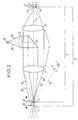
- FIG. 2 shows a modified embodiment of the invention, in each case Elements which correspond to the embodiment according to FIG. 1 with the same reference numerals as in Figure 1 are provided.
- the entocentric includes optical unit 5 two lenses 5 ', 5 ".
- Edge rays 18, 18 ' are also shown, which represent the image of the respective object 1 or 1 'reflected compensation beam 8 the lenses 5 ', 5 "in positions marked by the crosses 11, 15 represent on the receiving unit 3.
- a light source 19 is shown in Figure 2, for example sequentially in sequence, according to red, green and blue light edge rays 20 shown via a lens 21, one between the lenses 5 ', 5 "arranged deflecting mirror 22 and the lens 5' as active Maps lighting to object 1 or 1 '.
- the of the light source 19 emitted colored light beams with different Light intensity reflected, so that 3 different on the receiving unit Light intensities can be determined. Because of the different detected light intensities can ultimately the color of the object 1 be determined. For this purpose, the determined signal amplitudes of the different Colors with values saved for the colors compared.
Landscapes
- Physics & Mathematics (AREA)
- General Physics & Mathematics (AREA)
- Length Measuring Devices By Optical Means (AREA)
- Fittings On The Vehicle Exterior For Carrying Loads, And Devices For Holding Or Mounting Articles (AREA)
- Prostheses (AREA)
- Measurement Of Optical Distance (AREA)
- Automatic Focus Adjustment (AREA)
Abstract
Description
- Figur 1
- eine schematische Darstellung einer ersten Ausführungsform der Erfindung mit drei unterschiedlichen Positionierungen eines Objekts und
- Figur 2
- eine schematische Darstellung einer weiteren Ausführungsform der Erfindung.
- 1, 1', 1"
- Objekte in verschiedenen Abständen
- 2, 2', 2"
- Abstände (2 = Nenntastweite)
- 3
- Zeilensensor
- 4
- Sensorelemente
- 5
- Entozentrische optische Einheit
- 5', 5"
- Linsen
- 6
- optische Achse
- 7
- Lichtsender
- 8
- Kompensationslichtstrahl
- 9
- Linse
- 10
- Punkt
- 11
- Kreuz
- 12
- Punkt
- 13
- Kreuz
- 14
- Punkt
- 15
- Kreuz
- 16, 16', 16"
- Randstrahlen
- 17
- Pfeile
- 18, 18'
- Randstrahlen
- 19
- Lichtquelle
- 20
- Randstrahlen
- 21
- Linse
- 22
- Umlenkspiegel
Claims (22)
- Verfahren zum Abbilden von Objekten auf einer ortsauflösenden Empfangseinheit, bei dem ein Objekt über eine entozentrische optische Einheit auf der Empfangseinheit als Objektbild abgebildet wird,
dadurch gekennzeichnet,daß zumindest ein Kompensationslichtsignal in Richtung des Objekts ausgesandt, von diesem reflektiert und über die optische Einheit auf die Empfangseinheit abgebildet wird,daß die Position des auf der Empfangseinheit auftreffenden Kompensationslichtsignals ermittelt wird unddaß in Abhängigkeit von der ermittelten Position eine vorhandene Abstandsabweichung des Objektes von einem bezüglich der Empfangseinheit vorgegebenen Referenzabstand kompensiert wird. - Verfahren nach Anspruch 1,
dadurch gekennzeichnet, daß als Referenzabstand die Nenntastweite des optischen Systems verwendet wird. - Verfahren nach Anspruch 1 oder 2,
dadurch gekennzeichnet,daß die Position des auf der Empfangseinheit auftreffenden Kompensationslichtsignals mit einer vorgegebenen Referenzposition verglichen wird und in Abhängigkeit von dem Vergleichsergebnis die Abstandsabweichung kompensiert wird, insbesonderedaß die Referenzposition durch Ermitteln der Position des auf die Empfangseinheit auftreffenden Kompensationslichtsignals bei einer Anordnung des Objekts im Referenzabstand, insbesondere in der Nenntastweite bestimmt wird. - Verfahren nach einem der vorhergehenden Ansprüche,
dadurch gekennzeichnet, daß unterschiedlichen Positionen auf der Empfangseinheit jeweils vorgegebene Korrekturwerte zugeordnet sind und daß in Abhängigkeit von der ermittelten Position des auf der Empfangseinheit auftreffenden Kompensationslichtsignals die Kompensation anhand des/der dieser Position zugeordneten Korrekturwertes/ Korrekturwerte erfolgt. - Verfahren nach einem der vorhergehenden Ansprüche,
dadurch gekennzeichnet,daß das Kompensationslichtsignal unter einem Winkel (α) ungleich Null zur optischen Achse der optischen Einheit in Richtung des Objekts ausgesandt wird und/oderdaß das Kompensationslichtsignal als kolliminiertes Lichtbündel ausgesandt und/oder über eine weitere optische Einheit auf das Objekt abgebildet, insbesondere fokussiert wird. - Verfahren nach einem der vorhergehenden Ansprüche,
dadurch gekennzeichnet, daß für die Kompensationslichtsignale gepulstes Licht verwendet wird. - Verfahren nach einem der vorhergehenden Ansprüche,
dadurch gekennzeichnet, daß zum Abbilden des Objektes dieses aktiv beleuchtet wird, insbesondere indem Beleuchtungslichtsignale in Richtung des Objektes ausgesandt werden, wobei für die aktive Beleuchtung bevorzugt gepulstes Licht verwendet wird. - Verfahren nach Anspruch 6 oder 7,
dadurch gekennzeichnet, daß die Pulsfrequenzen der Kompensationslichtsignale und der Beleuchtungslichtsignale unterschiedlich sind. - Verfahren nach einem der Ansprüche 7 oder 8,
dadurch gekennzeichnet, daß für die Beleuchtungslichtsignale sichtbares Licht und/oder Licht im Infrarotbereich verwendet wird. - Verfahren nach einem der Ansprüche 7 bis 9,
dadurch gekennzeichnet,daß die Kompensationslichtsignale und die Beleuchtungslichtsignale jeweils zeitlich aufeinanderfolgend und insbesondere nicht überlappend ausgesandt werden oderdaß die Kompensationslichtsignale und die Beleuchtungslichtsignale zeitlich überlappend, insbesondere gleichzeitig ausgesandt werden. - Verfahren nach einem der Ansprüche 7 bis 10,
dadurch gekennzeichnet, daß die Kompensationslichtsignale und die Beleuchtungslichtsignale unterschiedliche Lichtintensitäten besitzen. - Verfahren nach einem der Ansprüche 7 bis 11,
dadurch gekennzeichnet, daß die Kompensationslichtsignale und die Beleuchtungslichtsignale von der gleichen Lichtsendeeinheit ausgesandt werden oder daß die Kompensationslichtsignale und die Beleuchtungslichtsignale von unterschiedlichen Lichtsendeeinheiten ausgesandt werden. - Verfahren nach einem der vorhergehenden Ansprüche,
dadurch gekennzeichnet,daß für die Kompensationslichtsignale sichtbares Licht und/oder Licht im Infrarotbereich verwendet wird und/oderdaß die Kompensationslichtsignale über die Oberfläche des Objekts geführt werden. - Verfahren nach einem der vorhergehenden Ansprüche,
dadurch gekennzeichnet, daß die Größe des Objektbildes ermittelt wird, daß aus der ermittelten Position des auf der Empfangseinheit auftreffenden Kompensationslichtsignals, insbesondere aus dem Vergleichsergebnis, die Abstandsabweichung des Objekts von dem Referenzabstand, insbesondere der Nenntastweite, bestimmt wird und daß aus der ermittelten Größe des Objektbildes und der bestimmten Abstandsabweichung eine korrigierte Größe des Objektbildes bestimmt wird, die der Größe des Objektbildes bei einer Positionierung im Referenzabstand, insbesondere in der Nenntastweite zur Empfangseinheit entspricht. - Verfahren nach einem der vorhergehenden Ansprüche,
dadurch gekennzeichnet, daß zumindest bereichsweise die Kontur des Objektbildes erfaßt wird, daß aus der ermittelten Position des auf der Empfangseinheit auftreffenden Kompensationslichtsignals, insbesondere aus dem Vergleichsergebnis, die Abstandsabweichung des Objekts von dem Referenzabstand, insbesondere der Nenntastweite bestimmt wird und daß aus der erfaßten Kontur des Objektbildes und der bestimmten Abstandsabweichung eine korrigierte Kontur des Objektbildes bestimmt wird, die der Kontur des Objektbildes bei einer Positionierung im Referenzabstand, insbesondere in der Nenntastweite zur Empfangseinheit entspricht. - Verfahren nach einem der vorhergehenden Ansprüche,
dadurch gekennzeichnet, daß die Position einer Kante des Objektbildes ermittelt wird, daß aus der ermittelten Position des auf der Empfangseinheit auftreffenden Kompensationslichtsignals, insbesondere aus dem Vergleichsergebnis, die Abstandsabweichung des Objekts von dem Referenzabstand, insbesondere der Nenntastweite, bestimmt wird und daß aus der ermittelten Position der Kante des Objektbildes und der bestimmten Abstandsabweichung eine korrigierte Position der Kante bestimmt wird, die der Position der Kante des Objektbildes bei einer Positionierung im Referenzabstand, insbesondere in der Nenntastweite zur Empfangseinheit entspricht. - Verfahren nach einem der vorhergehenden Ansprüche,
dadurch gekennzeichnet, daß die Lichtintensität des Objektbildes ermittelt wird, daß aus der ermittelten Position des auf der Empfangseinheit auftreffenden Kompensationslichtsignals, insbesondere aus dem Vergleichsergebnis, die Abstandsabweichung des Objekts von dem Referenzabstand, insbesondere der Nenntastweite, bestimmt wird und daß aus der ermittelten Lichtintensität des Objektbildes und der bestimmten Abstandsabweichung eine korrigierte Lichtintensität bestimmt wird, die der Lichtintensität des Objektbildes bei einer Positionierung im Referenzabstand, insbesondere in der Nenntastweite zur Empfangseinheit entspricht. - Verfahren nach Anspruch 17,
dadurch gekennzeichnet, daß Beleuchtungslichtsignale mit verschiedenen Farben, insbesondere drei verschiedenen Farben, verwendet werden und daß für jede der Farben die Lichtintensität des Objektbildes ermittelt und die korrigierte Lichtintensität bestimmt wird - Verfahren nach einem der vorhergehenden Ansprüche.
dadurch gekennzeichnet, daß das Objekt solange in Richtung des Referenzabstandes bewegt wird, bis die Position des auf der Empfangseinheit auftreffenden Kompensationslichtsignals mit der Referenzposition zumindest bis auf einen vorgegebenen Toleranzwert übereinstimmt. - Optoelektronische Vorrichtung mit einer ortsauflösenden Empfangseinheit (3),mit einer entozentrischen optischen Einheit (5) zum Abbilden von Objekten auf der Empfangseinheit (3),mit zumindest einem Lichtsender (7) zum Aussenden eines Kompensationslichtsignals (8) in Richtung des Objekts (1, 1', 1"),wobei die optische Einheit (5) und die Empfangseinheit (3) so angeordnet sind, daß das von dem Objekt (1, 1', 1") reflektierte Kompensationslichtsignal (8) über die optische Einheit (5) auf die Empfangseinheit (3) abbildbar ist,mit einer Positionsbestimmungseinheit zum Ermitteln der Position (13, 15) des auf der Empfangseinheit (3) auftreffenden Kompensationslichtsignals (8) undmit einer Kompensationseinheit zur Kompensierung einer vorhandenen Abstandsabweichung des Objektes (1, 1', 1") von einem bezüglich der Empfangseinheit vorgegebenen Referenzabstand (2) in Abhängigkeit von der ermittelten Position (13, 15), insbesondere zum Durchführen des Verfahrens nach einem der vorhergehenden Ansprüche.
- Optoelektronische Vorrichtung nach Anspruch 20,
dadurch gekennzeichnet,daß eine Vergleichseinheit zum Vergleichen der ermittelten Position (13, 15) mit einer vorgegebenen Referenzposition (11) vorgesehen ist und/oderdaß die Empfangseinheit (3) als eindimensionaler Sensor, insbesondere als Zeilensensor, oder als zweidimensionaler Sensor, insbesondere als Matrixsensor, ausgebildet ist. - Optoelektronische Vorrichtung nach einem der Ansprüche 20 oder 21,
dadurch gekennzeichnet,daß eine Lichtquelle (19) zur aktiven Beleuchtung des Objektes (1, 1', 1") vorgesehen ist, insbesonderedaß die Lichtquelle (19) durch den Lichtsender (7) gebildet wird.
Applications Claiming Priority (2)
| Application Number | Priority Date | Filing Date | Title |
|---|---|---|---|
| DE10014627A DE10014627A1 (de) | 2000-03-24 | 2000-03-24 | Verfahren und Vorrichtung zum Abbilden von Objekten |
| DE10014627 | 2000-03-24 |
Publications (2)
| Publication Number | Publication Date |
|---|---|
| EP1136787A1 true EP1136787A1 (de) | 2001-09-26 |
| EP1136787B1 EP1136787B1 (de) | 2005-01-19 |
Family
ID=7636173
Family Applications (1)
| Application Number | Title | Priority Date | Filing Date |
|---|---|---|---|
| EP01105913A Expired - Lifetime EP1136787B1 (de) | 2000-03-24 | 2001-03-09 | Objektabbildung mit Abstandskompensation ( Grösse, Farbe ) |
Country Status (3)
| Country | Link |
|---|---|
| EP (1) | EP1136787B1 (de) |
| AT (1) | ATE287523T1 (de) |
| DE (2) | DE10014627A1 (de) |
Cited By (3)
| Publication number | Priority date | Publication date | Assignee | Title |
|---|---|---|---|---|
| DE10317447A1 (de) * | 2003-04-16 | 2004-11-18 | Nexpress Solutions Llc | Verfahren und Sensoreinrichtung zum Erfassen von Farben |
| EP2479534A1 (de) * | 2011-01-22 | 2012-07-25 | Sick AG | Optoelektronischer Sensor |
| DE102012208248B3 (de) * | 2012-05-16 | 2013-08-29 | Astech Angewandte Sensortechnik Gmbh | Abstandsvariationskompensiertes Farbsensorsystem |
Families Citing this family (1)
| Publication number | Priority date | Publication date | Assignee | Title |
|---|---|---|---|---|
| DE102022125115B4 (de) | 2022-09-29 | 2025-08-14 | Jenoptik Industrial Metrology Germany Gmbh | Optische Messverfahren und optische Messvorrichtungen |
Citations (6)
| Publication number | Priority date | Publication date | Assignee | Title |
|---|---|---|---|---|
| EP0031973A2 (de) * | 1979-12-13 | 1981-07-15 | Philips Electronics Uk Limited | Messeinrichtung für Objekte |
| US4371783A (en) * | 1980-11-03 | 1983-02-01 | Hoffmann-La Roche Inc. | Multichannel fiber optic light guide for capsule inspection |
| JPS6073403A (ja) * | 1983-09-30 | 1985-04-25 | Mitsubishi Heavy Ind Ltd | エツジ位置検出方式 |
| US5117101A (en) * | 1990-08-13 | 1992-05-26 | Technostics Corporation | Tristimulus color recognition system with means for compensating for variations in light source color |
| DE29515614U1 (de) * | 1995-10-02 | 1995-11-16 | Erhardt + Leimer GmbH, 86157 Augsburg | Vorrichtung zur Lageerfassung von laufenden Warenbahnen |
| FR2746705A1 (fr) * | 1996-03-27 | 1997-10-03 | Heidelberg Harris Sa | Dispositif de mesure sans contact de modifications de position d'une nappe continue de matiere |
Family Cites Families (5)
| Publication number | Priority date | Publication date | Assignee | Title |
|---|---|---|---|---|
| JPS6465460A (en) * | 1987-09-07 | 1989-03-10 | Hitachi Ltd | Space filter type speed measuring instrument |
| DE3730396A1 (de) * | 1987-09-10 | 1989-03-23 | Ipr Intelligente Peripherien F | Verfahren und vorrichtung zur beruehrungslosen bestimmung der backenposition am greifer eines handhabungsautomaten |
| GB9117974D0 (en) * | 1991-08-20 | 1991-10-09 | Renishaw Metrology Ltd | Non-contact trigger probe |
| DE19735246C2 (de) * | 1997-08-14 | 1999-07-15 | Bayern Freistaat | Verfahren zur Bestimmung eines Volumens |
| DE19853302A1 (de) * | 1998-11-19 | 2000-05-25 | Waelde Juergen | Optischer Abstandsmesser |
-
2000
- 2000-03-24 DE DE10014627A patent/DE10014627A1/de not_active Withdrawn
-
2001
- 2001-03-09 AT AT01105913T patent/ATE287523T1/de not_active IP Right Cessation
- 2001-03-09 DE DE50105095T patent/DE50105095D1/de not_active Expired - Lifetime
- 2001-03-09 EP EP01105913A patent/EP1136787B1/de not_active Expired - Lifetime
Patent Citations (6)
| Publication number | Priority date | Publication date | Assignee | Title |
|---|---|---|---|---|
| EP0031973A2 (de) * | 1979-12-13 | 1981-07-15 | Philips Electronics Uk Limited | Messeinrichtung für Objekte |
| US4371783A (en) * | 1980-11-03 | 1983-02-01 | Hoffmann-La Roche Inc. | Multichannel fiber optic light guide for capsule inspection |
| JPS6073403A (ja) * | 1983-09-30 | 1985-04-25 | Mitsubishi Heavy Ind Ltd | エツジ位置検出方式 |
| US5117101A (en) * | 1990-08-13 | 1992-05-26 | Technostics Corporation | Tristimulus color recognition system with means for compensating for variations in light source color |
| DE29515614U1 (de) * | 1995-10-02 | 1995-11-16 | Erhardt + Leimer GmbH, 86157 Augsburg | Vorrichtung zur Lageerfassung von laufenden Warenbahnen |
| FR2746705A1 (fr) * | 1996-03-27 | 1997-10-03 | Heidelberg Harris Sa | Dispositif de mesure sans contact de modifications de position d'une nappe continue de matiere |
Cited By (3)
| Publication number | Priority date | Publication date | Assignee | Title |
|---|---|---|---|---|
| DE10317447A1 (de) * | 2003-04-16 | 2004-11-18 | Nexpress Solutions Llc | Verfahren und Sensoreinrichtung zum Erfassen von Farben |
| EP2479534A1 (de) * | 2011-01-22 | 2012-07-25 | Sick AG | Optoelektronischer Sensor |
| DE102012208248B3 (de) * | 2012-05-16 | 2013-08-29 | Astech Angewandte Sensortechnik Gmbh | Abstandsvariationskompensiertes Farbsensorsystem |
Also Published As
| Publication number | Publication date |
|---|---|
| DE10014627A1 (de) | 2001-09-27 |
| DE50105095D1 (de) | 2005-02-24 |
| EP1136787B1 (de) | 2005-01-19 |
| ATE287523T1 (de) | 2005-02-15 |
Similar Documents
| Publication | Publication Date | Title |
|---|---|---|
| EP0295433B1 (de) | Registermesssystem, wie es im Offsetbereich zur Kontrolle der Lage der Druckplatten Anwendung findet | |
| EP0689700B1 (de) | Verfahren zur aufnahme von strichcodierungen | |
| DE3815375C5 (de) | Vorrichtung zum Erkennen eines Dokuments | |
| EP2619525B1 (de) | Verfahren zum optischen antasten einer kante in oder an einem oberlächenbereich | |
| EP2511648B1 (de) | Messanordnung und Verfahren zur Bestimmung mindestens der Crimphöhe eines Leitercrimps | |
| EP0400408A2 (de) | Verfahren zur Ausrichtung zweier Lichtwellenleiter-Faserenden und Einrichtung zur Durchführung des Verfahrens | |
| DE102015119707B3 (de) | Verfahren zum Ausrichten eines Laserscanners und Laserscanneranordung | |
| EP4150370B1 (de) | Verfahren zum kalibrieren und/oder justieren und steuereinheit für ein lidar-system, lidar-system und arbeitsvorrichtung | |
| EP0892280A2 (de) | Verfahren zum Betrieb einer opto-elektronischen Sensoranordnung | |
| WO1992008103A1 (de) | Verfahren und anordnung zur optoelektronischen vermessung von gegenständen | |
| DE102010032800A1 (de) | Verfahren und Vorrichtung zum Kalibrieren einer Laserbearbeitungsmaschine | |
| DE102021128707A1 (de) | Verfahren zum Kalibrieren eines oder mehrerer optischer Sensoren eines Laserbearbeitungskopfes, Laserbearbeitungskopf und Laserbearbeitungssystem | |
| DE2354141A1 (de) | Verfahren zum untersuchen einer oberflaeche und vorrichtung zur durchfuehrung dieses verfahrens | |
| EP0962746B1 (de) | Verfahren und Vorrichtung, ob zwei hintereinander angeordnete Wellen fluchten | |
| DD292318A5 (de) | Vorrichtung fuer kontaktlose, raeumliche messungen | |
| DE102019128907A1 (de) | Filterung von Messdaten eines aktiven optischen Sensorsystems | |
| DE19732668A1 (de) | Vorrichtung und Verfahren zur Kalibrierung von Strahlabtastvorrichtungen | |
| DE102005047200B4 (de) | Verfahren zur Korrektur einer Steuerung eines optischen Scanners in einer Vorrichtung zur scannenden Abbildung einer Probe und Vorrichtung zur Erzeugung eines Bildes einer Probe durch Abscannen der Probe | |
| EP1178344A1 (de) | Verfahren und Vorrichtung zur Bildentzerrung in der Scanmikroskopie und Scanmikroskop | |
| DE102018108154B4 (de) | Kalibriervorrichtung und Kalibrierverfahren für ein Kamerasystem | |
| DE10153581A1 (de) | Verfahren und Vorrichtung zur Ermittlung der Wirkkontur von Rotationswerkzeugen | |
| EP1136787B1 (de) | Objektabbildung mit Abstandskompensation ( Grösse, Farbe ) | |
| EP0689664B1 (de) | Vorrichtung zur lagebestimmung eines positionierkörpers relativ zu einem bezugskörper | |
| WO2004029691A1 (de) | Verfahren und vorrichtung zum bestimmen eines abstands, autofokus-modul, mikroskop und verfahren zum autofokussieren eines mikroskops | |
| DE3703505C2 (de) |
Legal Events
| Date | Code | Title | Description |
|---|---|---|---|
| PUAI | Public reference made under article 153(3) epc to a published international application that has entered the european phase |
Free format text: ORIGINAL CODE: 0009012 |
|
| AK | Designated contracting states |
Kind code of ref document: A1 Designated state(s): AT BE CH CY DE DK ES FI FR GB GR IE IT LI LU MC NL PT SE TR |
|
| AX | Request for extension of the european patent |
Free format text: AL;LT;LV;MK;RO;SI |
|
| 17P | Request for examination filed |
Effective date: 20011120 |
|
| AKX | Designation fees paid |
Free format text: AT BE CH CY DE DK ES FI FR GB GR IE IT LI LU MC NL PT SE TR |
|
| GRAP | Despatch of communication of intention to grant a patent |
Free format text: ORIGINAL CODE: EPIDOSNIGR1 |
|
| GRAS | Grant fee paid |
Free format text: ORIGINAL CODE: EPIDOSNIGR3 |
|
| GRAA | (expected) grant |
Free format text: ORIGINAL CODE: 0009210 |
|
| AK | Designated contracting states |
Kind code of ref document: B1 Designated state(s): AT BE CH CY DE DK ES FI FR GB GR IE IT LI LU MC NL PT SE TR |
|
| PG25 | Lapsed in a contracting state [announced via postgrant information from national office to epo] |
Ref country code: GB Free format text: LAPSE BECAUSE OF FAILURE TO SUBMIT A TRANSLATION OF THE DESCRIPTION OR TO PAY THE FEE WITHIN THE PRESCRIBED TIME-LIMIT Effective date: 20050119 Ref country code: FR Free format text: LAPSE BECAUSE OF NON-PAYMENT OF DUE FEES Effective date: 20050119 Ref country code: IE Free format text: LAPSE BECAUSE OF FAILURE TO SUBMIT A TRANSLATION OF THE DESCRIPTION OR TO PAY THE FEE WITHIN THE PRESCRIBED TIME-LIMIT Effective date: 20050119 Ref country code: NL Free format text: LAPSE BECAUSE OF FAILURE TO SUBMIT A TRANSLATION OF THE DESCRIPTION OR TO PAY THE FEE WITHIN THE PRESCRIBED TIME-LIMIT Effective date: 20050119 Ref country code: TR Free format text: LAPSE BECAUSE OF FAILURE TO SUBMIT A TRANSLATION OF THE DESCRIPTION OR TO PAY THE FEE WITHIN THE PRESCRIBED TIME-LIMIT Effective date: 20050119 Ref country code: FI Free format text: LAPSE BECAUSE OF FAILURE TO SUBMIT A TRANSLATION OF THE DESCRIPTION OR TO PAY THE FEE WITHIN THE PRESCRIBED TIME-LIMIT Effective date: 20050119 |
|
| REG | Reference to a national code |
Ref country code: GB Ref legal event code: FG4D Free format text: NOT ENGLISH |
|
| REG | Reference to a national code |
Ref country code: CH Ref legal event code: EP |
|
| REG | Reference to a national code |
Ref country code: IE Ref legal event code: FG4D Free format text: GERMAN |
|
| REF | Corresponds to: |
Ref document number: 50105095 Country of ref document: DE Date of ref document: 20050224 Kind code of ref document: P |
|
| PG25 | Lapsed in a contracting state [announced via postgrant information from national office to epo] |
Ref country code: CY Free format text: LAPSE BECAUSE OF FAILURE TO SUBMIT A TRANSLATION OF THE DESCRIPTION OR TO PAY THE FEE WITHIN THE PRESCRIBED TIME-LIMIT Effective date: 20050309 Ref country code: LU Free format text: LAPSE BECAUSE OF NON-PAYMENT OF DUE FEES Effective date: 20050309 Ref country code: AT Free format text: LAPSE BECAUSE OF NON-PAYMENT OF DUE FEES Effective date: 20050309 |
|
| PG25 | Lapsed in a contracting state [announced via postgrant information from national office to epo] |
Ref country code: BE Free format text: LAPSE BECAUSE OF NON-PAYMENT OF DUE FEES Effective date: 20050331 Ref country code: MC Free format text: LAPSE BECAUSE OF NON-PAYMENT OF DUE FEES Effective date: 20050331 |
|
| PG25 | Lapsed in a contracting state [announced via postgrant information from national office to epo] |
Ref country code: DK Free format text: LAPSE BECAUSE OF FAILURE TO SUBMIT A TRANSLATION OF THE DESCRIPTION OR TO PAY THE FEE WITHIN THE PRESCRIBED TIME-LIMIT Effective date: 20050419 Ref country code: GR Free format text: LAPSE BECAUSE OF FAILURE TO SUBMIT A TRANSLATION OF THE DESCRIPTION OR TO PAY THE FEE WITHIN THE PRESCRIBED TIME-LIMIT Effective date: 20050419 |
|
| REG | Reference to a national code |
Ref country code: SE Ref legal event code: TRGR |
|
| PG25 | Lapsed in a contracting state [announced via postgrant information from national office to epo] |
Ref country code: ES Free format text: LAPSE BECAUSE OF FAILURE TO SUBMIT A TRANSLATION OF THE DESCRIPTION OR TO PAY THE FEE WITHIN THE PRESCRIBED TIME-LIMIT Effective date: 20050430 |
|
| NLV1 | Nl: lapsed or annulled due to failure to fulfill the requirements of art. 29p and 29m of the patents act | ||
| GBV | Gb: ep patent (uk) treated as always having been void in accordance with gb section 77(7)/1977 [no translation filed] |
Effective date: 20050119 |
|
| REG | Reference to a national code |
Ref country code: IE Ref legal event code: FD4D |
|
| BERE | Be: lapsed |
Owner name: SICK A.G. Effective date: 20050331 |
|
| PLBE | No opposition filed within time limit |
Free format text: ORIGINAL CODE: 0009261 |
|
| STAA | Information on the status of an ep patent application or granted ep patent |
Free format text: STATUS: NO OPPOSITION FILED WITHIN TIME LIMIT |
|
| 26N | No opposition filed |
Effective date: 20051020 |
|
| EN | Fr: translation not filed | ||
| BERE | Be: lapsed |
Owner name: SICK A.G. Effective date: 20050331 |
|
| PG25 | Lapsed in a contracting state [announced via postgrant information from national office to epo] |
Ref country code: PT Free format text: LAPSE BECAUSE OF NON-PAYMENT OF DUE FEES Effective date: 20050619 |
|
| PGFP | Annual fee paid to national office [announced via postgrant information from national office to epo] |
Ref country code: SE Payment date: 20130319 Year of fee payment: 13 |
|
| REG | Reference to a national code |
Ref country code: SE Ref legal event code: EUG |
|
| PG25 | Lapsed in a contracting state [announced via postgrant information from national office to epo] |
Ref country code: SE Free format text: LAPSE BECAUSE OF NON-PAYMENT OF DUE FEES Effective date: 20140310 |
|
| PGFP | Annual fee paid to national office [announced via postgrant information from national office to epo] |
Ref country code: IT Payment date: 20150326 Year of fee payment: 15 |
|
| PG25 | Lapsed in a contracting state [announced via postgrant information from national office to epo] |
Ref country code: IT Free format text: LAPSE BECAUSE OF NON-PAYMENT OF DUE FEES Effective date: 20160309 |
|
| PGFP | Annual fee paid to national office [announced via postgrant information from national office to epo] |
Ref country code: CH Payment date: 20170327 Year of fee payment: 17 |
|
| REG | Reference to a national code |
Ref country code: CH Ref legal event code: PL |
|
| PG25 | Lapsed in a contracting state [announced via postgrant information from national office to epo] |
Ref country code: CH Free format text: LAPSE BECAUSE OF NON-PAYMENT OF DUE FEES Effective date: 20180331 Ref country code: LI Free format text: LAPSE BECAUSE OF NON-PAYMENT OF DUE FEES Effective date: 20180331 |
|
| PGFP | Annual fee paid to national office [announced via postgrant information from national office to epo] |
Ref country code: DE Payment date: 20190325 Year of fee payment: 19 |
|
| REG | Reference to a national code |
Ref country code: DE Ref legal event code: R119 Ref document number: 50105095 Country of ref document: DE |
|
| PG25 | Lapsed in a contracting state [announced via postgrant information from national office to epo] |
Ref country code: DE Free format text: LAPSE BECAUSE OF NON-PAYMENT OF DUE FEES Effective date: 20201001 |