EP1136576A1 - Bottom pour electroslag refining systems with controlled electric current path - Google Patents
Bottom pour electroslag refining systems with controlled electric current path Download PDFInfo
- Publication number
- EP1136576A1 EP1136576A1 EP00302292A EP00302292A EP1136576A1 EP 1136576 A1 EP1136576 A1 EP 1136576A1 EP 00302292 A EP00302292 A EP 00302292A EP 00302292 A EP00302292 A EP 00302292A EP 1136576 A1 EP1136576 A1 EP 1136576A1
- Authority
- EP
- European Patent Office
- Prior art keywords
- liquid metal
- refined liquid
- crucible
- electroslag refining
- viscosity
- Prior art date
- Legal status (The legal status is an assumption and is not a legal conclusion. Google has not performed a legal analysis and makes no representation as to the accuracy of the status listed.)
- Granted
Links
- 238000007670 refining Methods 0.000 title claims abstract description 158
- 229910001338 liquidmetal Inorganic materials 0.000 claims abstract description 135
- 239000002994 raw material Substances 0.000 claims abstract description 58
- 239000002893 slag Substances 0.000 claims abstract description 29
- 238000002844 melting Methods 0.000 claims abstract description 17
- 230000008018 melting Effects 0.000 claims abstract description 17
- 238000010292 electrical insulation Methods 0.000 claims abstract description 5
- 238000000034 method Methods 0.000 claims description 22
- 239000007769 metal material Substances 0.000 claims description 6
- 239000002184 metal Substances 0.000 description 18
- 229910052751 metal Inorganic materials 0.000 description 18
- 230000006698 induction Effects 0.000 description 17
- 239000007788 liquid Substances 0.000 description 14
- 238000010438 heat treatment Methods 0.000 description 7
- 150000002739 metals Chemical class 0.000 description 4
- RYGMFSIKBFXOCR-UHFFFAOYSA-N Copper Chemical compound [Cu] RYGMFSIKBFXOCR-UHFFFAOYSA-N 0.000 description 3
- PXHVJJICTQNCMI-UHFFFAOYSA-N Nickel Chemical compound [Ni] PXHVJJICTQNCMI-UHFFFAOYSA-N 0.000 description 3
- 238000005266 casting Methods 0.000 description 3
- 229910052802 copper Inorganic materials 0.000 description 3
- 239000010949 copper Substances 0.000 description 3
- 230000000977 initiatory effect Effects 0.000 description 3
- 239000000155 melt Substances 0.000 description 3
- 239000007858 starting material Substances 0.000 description 3
- 229910045601 alloy Inorganic materials 0.000 description 2
- 239000000956 alloy Substances 0.000 description 2
- 239000010936 titanium Substances 0.000 description 2
- 238000010313 vacuum arc remelting Methods 0.000 description 2
- XEEYBQQBJWHFJM-UHFFFAOYSA-N Iron Chemical compound [Fe] XEEYBQQBJWHFJM-UHFFFAOYSA-N 0.000 description 1
- ZOKXTWBITQBERF-UHFFFAOYSA-N Molybdenum Chemical compound [Mo] ZOKXTWBITQBERF-UHFFFAOYSA-N 0.000 description 1
- RTAQQCXQSZGOHL-UHFFFAOYSA-N Titanium Chemical compound [Ti] RTAQQCXQSZGOHL-UHFFFAOYSA-N 0.000 description 1
- 238000000889 atomisation Methods 0.000 description 1
- 230000015572 biosynthetic process Effects 0.000 description 1
- 239000010941 cobalt Substances 0.000 description 1
- 229910017052 cobalt Inorganic materials 0.000 description 1
- GUTLYIVDDKVIGB-UHFFFAOYSA-N cobalt atom Chemical compound [Co] GUTLYIVDDKVIGB-UHFFFAOYSA-N 0.000 description 1
- 230000005484 gravity Effects 0.000 description 1
- 238000009413 insulation Methods 0.000 description 1
- 238000005495 investment casting Methods 0.000 description 1
- 238000002074 melt spinning Methods 0.000 description 1
- 229910052750 molybdenum Inorganic materials 0.000 description 1
- 239000011733 molybdenum Substances 0.000 description 1
- 229910052759 nickel Inorganic materials 0.000 description 1
- 239000000843 powder Substances 0.000 description 1
- 238000000746 purification Methods 0.000 description 1
- 239000007787 solid Substances 0.000 description 1
- 238000007711 solidification Methods 0.000 description 1
- 230000008023 solidification Effects 0.000 description 1
- 238000009718 spray deposition Methods 0.000 description 1
- 229910052719 titanium Inorganic materials 0.000 description 1
- 230000007704 transition Effects 0.000 description 1
Images
Classifications
-
- C—CHEMISTRY; METALLURGY
- C22—METALLURGY; FERROUS OR NON-FERROUS ALLOYS; TREATMENT OF ALLOYS OR NON-FERROUS METALS
- C22B—PRODUCTION AND REFINING OF METALS; PRETREATMENT OF RAW MATERIALS
- C22B9/00—General processes of refining or remelting of metals; Apparatus for electroslag or arc remelting of metals
- C22B9/16—Remelting metals
- C22B9/18—Electroslag remelting
-
- B—PERFORMING OPERATIONS; TRANSPORTING
- B22—CASTING; POWDER METALLURGY
- B22D—CASTING OF METALS; CASTING OF OTHER SUBSTANCES BY THE SAME PROCESSES OR DEVICES
- B22D23/00—Casting processes not provided for in groups B22D1/00 - B22D21/00
- B22D23/06—Melting-down metal, e.g. metal particles, in the mould
- B22D23/10—Electroslag casting
Definitions
- the invention relates to electroslag refining systems and methods for electroslag refining.
- the invention related to bottom pour electroslag refining systems and methods.
- Electroslag refining comprises a process that is generally used to melt and refine various metals.
- iron (Fe), nickel (Ni), cobalt (Co), and titanium (Ti) based metals and alloys can be refined by an electroslag refining system and process.
- electroslag refining system comprises an consumable electrode formed from the alloy to be melted and refined, a liquid slag, and a cooled crucible, such as but not limited to a water-cooled copper crucible.
- the liquid slag can be heated by passing an electric current from a suitable current source to the consumable electrode then through the liquid slag and then to the crucible.
- the liquid slag is maintained at a temperature that is high enough to melt the consumable electrode.
- a refining process occurs as the consumable electrode melts and passes through the liquid slag.
- inclusions such as oxide inclusions, are exposed to the liquid slag and are dissolved, thus further refining the metal.
- the refining process includes the melting of metal from the consumable electrode and the formation of molten metal droplets. These droplets fall, for example by gravity, through the liquid slag, and are collected in a liquid metal pool.
- the pool is contained by the crucible, which is generally disposed below the pool.
- Electroslag refining systems generally include an induction-heated, segmented, water-cooled copper guide tube or cold induction guide (CIG).
- the cold induction guide is typically connected to the bottom of the electroslag refining system crucible.
- the cold induction guide includes an orifice from which a refined metal liquid stream can be extracted therefrom. This stream can be used as a liquid metal source for many solidification processes, including, but not limited to, powder atomization, spray deposition, investment casting, melt-spinning, strip casting, slab casting, and nucleated casting.
- Electroslag refining systems and cold induction guide structures are known in the art, for example as set forth in US Patent Nos. 5,160,532 to Benz et al., which is assigned to the Assignee of the instant invention and fully incorporated by reference.
- a cold induction guide structure may be used for facilitating a flow of refined liquid metal out of the electroslag refining system.
- the use of a cold induction guide structure includes the addition of further current and heat to the electroslag refining system.
- this addition current and heat adds costs to the refining process.
- the additional heat and current may provide insulation concerns, including heat and electrical insulation concerns.
- a bottom pour electroslag refining system refines raw material from a source of raw material into refined liquid metal.
- the bottom pour electroslag refining system comprises an electroslag refining crucible; a slag; a bottom pour structure that comprises an orifice from which refined liquid metal from the electroslag refining crucible can flow as a stream of refined liquid metal; and a current path.
- the current path is defined in the bottom pour electroslag refining system for applying current to the raw material for melting and refining the raw material.
- the melted and refined raw material forms a refined liquid metal pool in the electroslag refining crucible.
- the current that is applied by the current path is sufficient to provide the refined liquid metal in the refined liquid metal pool with a viscosity under which the refined liquid metal can flow through the orifice under its own viscosity.
- a further aspect of the invention provides a bottom pour electroslag refining method for refining raw material from a source of raw material into refined liquid metal in which the refined liquid metal can flow under its own viscosity.
- the method comprises providing raw material to be refined; providing an electroslag refining crucible; providing a slag in the electroslag refining crucible; providing a bottom pour structure for the electroslag refining crucible comprising an orifice from which refined liquid metal from the electroslag refining crucible can flow as a stream of refined liquid metal; establishing a current path; applying current to the raw material from the source of raw material for melting and refining the raw material; and forming a refined liquid metal pool in the electroslag refining crucible.
- the step of applying current comprises applying current at an amount that is sufficient to provide the refined liquid metal in the refined liquid metal pool with a viscosity so the refined liquid metal can flow out of the orifice under its own viscosity.
- Another aspect of the invention provides a bottom pour electroslag refining method for refining raw material from a source of raw material into refined liquid metal in which the refined liquid metal can flow under its own viscosity.
- the method comprises providing raw material to be refined; providing an electroslag refining crucible; providing a slag in the electroslag refining crucible; providing a bottom pour structure for the electroslag refining crucible comprising an orifice from which refined liquid metal from the electroslag refining crucible can flow as a stream of refined liquid metal; establishing a current path; applying current to the raw material from the source of raw material for melting and refining the raw material; and forming a refined liquid metal pool in the electroslag refining crucible.
- the step of applying current comprises applying current at an amount that is sufficient to provide the refined liquid metal in the refined liquid metal pool with a viscosity so the refined liquid metal can flow out of the orifice under its own viscosity.
- the step of applying current comprises at least one of: establishing a refined liquid metal pool that comprises a depth sufficient for the refined liquid metal to maintain a viscosity under which the refined liquid metal pool can flow through the orifice under its own viscosity; and applying current at a level that is sufficient to heat the refined liquid metal pool to a temperature in which the refined liquid metal pool maintains a viscosity under which the refined liquid metal can flow through the orifice under its own viscosity.
- the bottom pour system comprises means for electroslag refining; means for applying an electrical current to the means for electroslag refining; and means for producing a refined liquid metal pool.
- the current applied by means for applying current is sufficient to provide refined liquid metal in the refined liquid metal pool with a viscosity under which the refined liquid metal can flow through under its own viscosity.
- the bottom pour structure can be provided with refining systems, to provide the refining system with an outlet for dispensing a stream of refined liquid metal.
- refining systems to provide the refining system with an outlet for dispensing a stream of refined liquid metal.
- the provision of a bottom pour structure, as embodied by the invention avoids the need for a cold induction guide structure, if the refined liquid metal in the refining system is sufficiently heated to form a stream without added heating, such as by induction heaters of a cold induction guide structure.
- the refining system may comprise any appropriate metal melting and refining system, such as but not limited to electroslag refining systems, vacuum induction melt (VIM) systems, vacuum arc remelting (VAR) systems, and other such systems that pertain to the purification of metals.
- VIM vacuum induction melt
- VAR vacuum arc remelting
- the bottom pour structure for an electroslag refining system can rely solely on heat that is generated by an electroslag refining system to permit a stream of refined liquid metal to flow therefrom.
- the bottom pour structure for an electroslag refining system does not rely on heat generated by a cold induction guide structure for dispensing a stream of refined liquid metal.
- the bottom pour structure for an electroslag refining system permits bottom pouring of a stream of refined liquid metal, in which the stream of refined liquid metal can be controlled by the amount of heat applied to the electroslag refining system. Additionally, the bottom pour structure for an electroslag refining system does not rely on heat generated by any other outside power supply, regardless of the form of the power supply.
- Electroslag refining systems can produce a liquid metal stream that can flow through an electroslag refining system orifice (hereinafter "orifice"), in the absence of cold induction power under certain operating conditions.
- an electroslag refining system orifice hereinafter "orifice"
- One of these conditions may occur when a refined metal liquid level in a crucible of the electroslag refining system is sufficiently low.
- the refined metal liquid level will be sufficiently low when energy, which is applied to melt and refine the metal, can maintain the refined liquid metal sufficiently viscous, which means that the viscosity of the refined liquid metal is sufficient for refined liquid metal to flow through the orifice without requiring further heating.
- the refined liquid metal that has been refined under these conditions will maintain sufficient viscosity for flow without further heating, for example heating originating from a cold induction guide structure.
- the high temperatures comprise temperatures generated by passing a current through the electroslag refining system for electroslag refining.
- the exact temperature may vary depending on the metal being refined, refining conditions, degree of fluidity desired, and other such factors.
- the current is supplied from an appropriate current source and heats up the electrode. Heat is passed to the refined liquid metal regardless of the source of the refined liquid metal.
- the refined liquid metal may be metal that is melted from a consumable electrode and thereafter refined.
- the metal for melting and refining may originate from a source other than the electrode.
- the heated refined liquid metal is heated to sufficiently high temperatures in that the viscosity is sufficient for refined liquid metal flow out of the orifice, without additional application of heat. Therefore, heating, for example, by an induction heater, such as in a cold induction guide structure, need not be applied to the electroslag refining system with a bottom pour structure, as embodied by the invention.
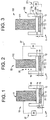
- Figures 1-3 illustrate configurations of electroslag refining systems with bottom pour structures, within the scope of the invention.
- FIG 1 illustrates a bottom pour structure 1 for one electroslag refining system 10, within the scope of the invention.
- the electroslag refining system 10 comprises a consumable electrode 11, for example a consumable electrode as set forth in US Patent No. 5,160,532 to Benz. Details to the consumable electrode feed mechanism for the electroslag refining system 10 and the crucible for the electroslag refining system are described in the Benz patent and are not set forth herein.
- the bottom pour structure 1 (Fig. 1), as embodied by the invention, comprises a bottom pour structure 12 (hereinafter "bottom pour structure”).
- the bottom pour structure 12 comprises an orifice or hole 13 through which a stream of liquid metal may be able to flow through.
- the electroslag refining system 10 comprises a slag 14 or "starter plate” of a metallic material, which is disposed on the bottom pour structure 12.
- the bottom pour structure 12 comprises a lower surface of a reservoir of the electroslag refining system crucible 18.
- the orifice 13 is initially closed during initiation phases of electroslag refining.
- initiation phases means phases in which the electroslag refining has created a stream of refined liquid metal through the orifice 13. During these phases, flow through the orifice 13 may be closed off by the slag 14, which has not been heated to a liquidus state.
- the electroslag refining proceeds by applying current through the electroslag refining system.
- the current melts portions of the consumable electrode 11 including portions of the consumable electrode 11 that are in contact with the slag 14.
- Electroslag refining of the metal from the consumable electrode 11 can occur, as is known in the art.
- the electroslag refining will then enter a "flow phase" of the electroslag refining operation, in which the melting of the starter plate 14 is complete.
- the melting of the starter plate 14 may form a refined liquid metal pool 15 above the orifice 13 in the crucible 18. Once the refined liquid metal pool 15 is formed, a stream 25 of refined liquid metal can exit the orifice 13.
- the bottom pour structure 1 for an electroslag refining system 10 provides flow without additional heating of the refined liquid metal, by a cold induction guide structure.
- One bottom pour condition occurs when the liquid level (alternatively referred to as "depth") in the refined metal pool 15 is low (as discussed below).
- Another bottom pour condition occurs as heat applied by passing a current for melting the slag 14 is sufficiently high (as discussed below) to create high temperature electroslag refining conditions.
- the electroslag refining configuration of Fig. 1 can achieve both of these bottom pour conditions.
- the refined liquid metal pool 15 can be formed with an overall depth d.
- the depth d is at a level sufficient to avoid significant heat loss from in the melted consumable electrode 11.
- the depth d is dimensioned to provide a liquid level in which the heat derived from the current applied for melting and refining is sufficient to maintain the refined liquid metal sufficiently viscous in the area of the orifice 13 that the refined liquid metal can flow through the orifice 13 without additional heat being applied thereto.
- the high temperature bottom pour condition can be obtained with the electroslag refining configuration of Fig. 1 by creating high temperatures during application of current for electroslag refining.
- the current for electroslag refining is passed through the consumable electrode 11, slag 14 and crucible 18 in a current path 27 illustrated in phantom in Fig. 1.
- the current path 27 includes a current supply device 28.
- the current that is applied for melting the consumable electrode 11 and the slag 14 is provided at levels sufficient for melting the consumable electrode 11 and the slag 14, and also is high enough to maintain the refined liquid metal sufficiently viscous in the area of the orifice 13 that the refined liquid metal can flow through the orifice 13 without additional heat being applied thereto.
- FIG. 2 illustrates an alternative embodiment of a bottom pour structure 1 in an electroslag refining system 50.
- the electrode 110 in the electroslag refining system 50 comprises an un-consumable electrode, in which the un-consumable electrode 110 provides a terminal the current being applied for heating and melting of raw material 20.
- the raw material 20 for refining is provided to the electroslag refining system 50 from any appropriate source that is separate from the current path, and can comprise solid raw material, liquid raw material, particulate raw material, powdered raw material, and combinations thereof.
- the un-consumable electrode 110 is not consumed, and can comprise a cooled electrode 110.
- the un-consumable electrode 110 can comprise a coolant-cooled, such as water-cooled, copper electrode.
- the un-consumable electrode 110 can be provided with appropriate shielding, such as at least one of heat and electrical shielding, for example but not limited to, a molybdenum shielding.
- raw material 20 is fed from a source into the crucible 18 by any appropriate feed device or means (not illustrated).
- Current is applied along a current path 27 that includes the un-consumable electrode 110, the liquid slag 14 and the crucible 18 of the electroslag refining system 50.
- the bottom pour structure 1 with the electroslag refining system 50 achieves the bottom pour conditions in a manner as described above, and the addition of further heat is avoided.
- FIG. 3 illustrates a further bottom pour structure with an electroslag refining system 100, as embodied by the invention for achieving bottom pour conditions in a manner as described above, in which addition of further heat to the refined liquid metal is avoided.
- the electroslag refining system crucible 18 of Fig. 3 comprises a split-crucible structure 180.
- the split-crucible structure 180 comprises at least two crucible portions, an upper split-crucible portion 19 and a lower split-crucible portion 21.
- Each of the split-crucible portions forms a part of the current. supply path 271 for the electroslag refining operations.
- the upper split-crucible portion 19 and lower split-crucible portion 21 are electrically insulated from each other by appropriate electrical insulation 201, thus the current path flows from the upper split-crucible portion 19, into the slag 14, and to a lower split-crucible portion 21.
- the electroslag refining system 100 with a bottom pour structure comprises a raw material supply 111.
- the raw material supply 111 does not form a portion of the current path, from which metal to be melted and refined originates. Therefore, the bottom pour structure with an electroslag refining system 100 can utilize stock consumable electrodes be used as raw material feed, however, connection of the current path 271 to the raw material supply 111 is not needed, as the current path is complete through the split-crucible structure 180 of the electroslag refining system 100.
- Electroslag refining by the electroslag refining system 100 with a bottom pour structure 1 and split-crucible structure 180 occurs by passing current from an appropriate current source 28 to the upper split-crucible portion 19. The current can then flow through the slag 14 and to the lower split-crucible portion 21, and back through the current path 27.
- the bottom pour structure 1 with the electroslag refining system 100 achieves the bottom pour conditions in a manner as described above, and the addition of further heat is avoided.
- the rate at which the stream 25 flow through the bottom pour structure 1 in electroslag refining systems within the scope of the invention can be controlled, and adjusted if desired.
- the control and adjustment of the stream flow may be related to the melt rate of each of the consumable electrode 11, the raw material 20, and the raw material supply 111 that can be adjusted to match the desired stream flow rate.
- the amount of current that is passed through the current path 27 may be controlled for starting flow, as in the transition from the initiation phase to a flow phase.
- the flow phase may comprise a steady state flow phase if the current applied, and thus the heat applied, is maintained at a relatively constant current level, in which the term constant is used with its conventional meaning by a person of ordinary skill in the art.
- the flow rate of the stream may be controlled and varied, if desired, by changing the current level applied thereto, in which lowering an applied current flow may lower a flow rate.
- increasing the current level may increase the heat applied to the electroslag refining systems, and a corresponding increase in the flow rate of the stream 25.
- the level of the refined liquid metal pool 15 in each electroslag refining system may also control the stream 25 flow through the orifice 13.
- the control of the stream flow generally increases with an increased height of refined liquid metal in the pool.
- a deeper pool of refined liquid metal will increase the flow rate of the stream as the pressure applied by the pool itself to the stream will increase its flow.
- reducing the depth of the pool will provide less refined liquid metal in the pool, and thus the flow of the stream will be lessened compared to a deeper pool of refined liquid metal.
Landscapes
- Engineering & Computer Science (AREA)
- Chemical & Material Sciences (AREA)
- Mechanical Engineering (AREA)
- Manufacturing & Machinery (AREA)
- Materials Engineering (AREA)
- Metallurgy (AREA)
- Organic Chemistry (AREA)
- Manufacture And Refinement Of Metals (AREA)
- Furnace Details (AREA)
Abstract
Description
- The invention relates to electroslag refining systems and methods for electroslag refining. In particular, the invention related to bottom pour electroslag refining systems and methods.
- Electroslag refining (ESR) comprises a process that is generally used to melt and refine various metals. For example and in no way limiting of the invention, iron (Fe), nickel (Ni), cobalt (Co), and titanium (Ti) based metals and alloys can be refined by an electroslag refining system and process. Typically, electroslag refining system comprises an consumable electrode formed from the alloy to be melted and refined, a liquid slag, and a cooled crucible, such as but not limited to a water-cooled copper crucible. The liquid slag can be heated by passing an electric current from a suitable current source to the consumable electrode then through the liquid slag and then to the crucible.
- The liquid slag is maintained at a temperature that is high enough to melt the consumable electrode. A refining process occurs as the consumable electrode melts and passes through the liquid slag. Also, inclusions, such as oxide inclusions, are exposed to the liquid slag and are dissolved, thus further refining the metal. The refining process includes the melting of metal from the consumable electrode and the formation of molten metal droplets. These droplets fall, for example by gravity, through the liquid slag, and are collected in a liquid metal pool. The pool is contained by the crucible, which is generally disposed below the pool.
- Electroslag refining systems generally include an induction-heated, segmented, water-cooled copper guide tube or cold induction guide (CIG). The cold induction guide is typically connected to the bottom of the electroslag refining system crucible. The cold induction guide includes an orifice from which a refined metal liquid stream can be extracted therefrom. This stream can be used as a liquid metal source for many solidification processes, including, but not limited to, powder atomization, spray deposition, investment casting, melt-spinning, strip casting, slab casting, and nucleated casting. Electroslag refining systems and cold induction guide structures are known in the art, for example as set forth in US Patent Nos. 5,160,532 to Benz et al., which is assigned to the Assignee of the instant invention and fully incorporated by reference.
- While known electroslag refining systems are effective in refining of metals, a cold induction guide structure may be used for facilitating a flow of refined liquid metal out of the electroslag refining system. The use of a cold induction guide structure includes the addition of further current and heat to the electroslag refining system. Of course, this addition current and heat adds costs to the refining process. Also, the additional heat and current may provide insulation concerns, including heat and electrical insulation concerns.
- Therefore, a need exists for an electroslag refining system that avoids adding additional heat and current to the electroslag refining system for facilitating refined liquid metal flow.
- One aspect of the invention provides a bottom pour electroslag refining system. A bottom pour electroslag refining system refines raw material from a source of raw material into refined liquid metal. The bottom pour electroslag refining system comprises an electroslag refining crucible; a slag; a bottom pour structure that comprises an orifice from which refined liquid metal from the electroslag refining crucible can flow as a stream of refined liquid metal; and a current path. The current path is defined in the bottom pour electroslag refining system for applying current to the raw material for melting and refining the raw material. The melted and refined raw material forms a refined liquid metal pool in the electroslag refining crucible. The current that is applied by the current path is sufficient to provide the refined liquid metal in the refined liquid metal pool with a viscosity under which the refined liquid metal can flow through the orifice under its own viscosity.
- A further aspect of the invention provides a bottom pour electroslag refining method for refining raw material from a source of raw material into refined liquid metal in which the refined liquid metal can flow under its own viscosity. The method comprises providing raw material to be refined; providing an electroslag refining crucible; providing a slag in the electroslag refining crucible; providing a bottom pour structure for the electroslag refining crucible comprising an orifice from which refined liquid metal from the electroslag refining crucible can flow as a stream of refined liquid metal; establishing a current path; applying current to the raw material from the source of raw material for melting and refining the raw material; and forming a refined liquid metal pool in the electroslag refining crucible. The step of applying current comprises applying current at an amount that is sufficient to provide the refined liquid metal in the refined liquid metal pool with a viscosity so the refined liquid metal can flow out of the orifice under its own viscosity.
- Another aspect of the invention provides a bottom pour electroslag refining method for refining raw material from a source of raw material into refined liquid metal in which the refined liquid metal can flow under its own viscosity. The method comprises providing raw material to be refined; providing an electroslag refining crucible; providing a slag in the electroslag refining crucible; providing a bottom pour structure for the electroslag refining crucible comprising an orifice from which refined liquid metal from the electroslag refining crucible can flow as a stream of refined liquid metal; establishing a current path; applying current to the raw material from the source of raw material for melting and refining the raw material; and forming a refined liquid metal pool in the electroslag refining crucible. The step of applying current comprises applying current at an amount that is sufficient to provide the refined liquid metal in the refined liquid metal pool with a viscosity so the refined liquid metal can flow out of the orifice under its own viscosity. The step of applying current comprises at least one of: establishing a refined liquid metal pool that comprises a depth sufficient for the refined liquid metal to maintain a viscosity under which the refined liquid metal pool can flow through the orifice under its own viscosity; and applying current at a level that is sufficient to heat the refined liquid metal pool to a temperature in which the refined liquid metal pool maintains a viscosity under which the refined liquid metal can flow through the orifice under its own viscosity.
- Another aspect of the invention sets forth a bottom pour system for electroslag refining of raw metallic material. The bottom pour system comprises means for electroslag refining; means for applying an electrical current to the means for electroslag refining; and means for producing a refined liquid metal pool. The current applied by means for applying current is sufficient to provide refined liquid metal in the refined liquid metal pool with a viscosity under which the refined liquid metal can flow through under its own viscosity.
- These and other aspects, advantages and salient features of the invention will become apparent from the following detailed description, which, when taken in conjunction with the annexed drawings, where like parts are designated by like reference characters throughout the drawings, disclose embodiments of the invention.
- The invention will now be described in greater detail, by way of example, with reference to the drawings, in which:-
- Figure 1 is a part-sectional, side schematic illustration of one bottom pour structure, as embodied by the invention, for an electroslag refining system;
- Figure 2 is a part-sectional, side schematic illustration of another bottom pour structure, as embodied by the invention; and
- Figure 3 a part-sectional, side schematic illustration of a further bottom pour structure.
-
- The bottom pour structure, as embodied by the invention, can be provided with refining systems, to provide the refining system with an outlet for dispensing a stream of refined liquid metal. The provision of a bottom pour structure, as embodied by the invention, avoids the need for a cold induction guide structure, if the refined liquid metal in the refining system is sufficiently heated to form a stream without added heating, such as by induction heaters of a cold induction guide structure. The refining system may comprise any appropriate metal melting and refining system, such as but not limited to electroslag refining systems, vacuum induction melt (VIM) systems, vacuum arc remelting (VAR) systems, and other such systems that pertain to the purification of metals. The following description of an electroslag refining system is merely exemplary, and this description is not intended to limit the invention in any manner.
- The bottom pour structure for an electroslag refining system, as embodied by the invention, can rely solely on heat that is generated by an electroslag refining system to permit a stream of refined liquid metal to flow therefrom. The bottom pour structure for an electroslag refining system does not rely on heat generated by a cold induction guide structure for dispensing a stream of refined liquid metal. The bottom pour structure for an electroslag refining system, as embodied by the invention, permits bottom pouring of a stream of refined liquid metal, in which the stream of refined liquid metal can be controlled by the amount of heat applied to the electroslag refining system. Additionally, the bottom pour structure for an electroslag refining system does not rely on heat generated by any other outside power supply, regardless of the form of the power supply.
- Electroslag refining systems can produce a liquid metal stream that can flow through an electroslag refining system orifice (hereinafter "orifice"), in the absence of cold induction power under certain operating conditions. One of these conditions may occur when a refined metal liquid level in a crucible of the electroslag refining system is sufficiently low. The refined metal liquid level will be sufficiently low when energy, which is applied to melt and refine the metal, can maintain the refined liquid metal sufficiently viscous, which means that the viscosity of the refined liquid metal is sufficient for refined liquid metal to flow through the orifice without requiring further heating. The refined liquid metal that has been refined under these conditions will maintain sufficient viscosity for flow without further heating, for example heating originating from a cold induction guide structure.
- Another operating condition that can produce a liquid metal stream flowing through an orifice in the absence of cold induction power under certain operating conditions may occur under electroslag refining conditions at high temperatures. The high temperatures, as embodied by the invention, comprise temperatures generated by passing a current through the electroslag refining system for electroslag refining. The exact temperature may vary depending on the metal being refined, refining conditions, degree of fluidity desired, and other such factors. The current is supplied from an appropriate current source and heats up the electrode. Heat is passed to the refined liquid metal regardless of the source of the refined liquid metal. For example, the refined liquid metal may be metal that is melted from a consumable electrode and thereafter refined. Alternatively, the metal for melting and refining may originate from a source other than the electrode. The heated refined liquid metal is heated to sufficiently high temperatures in that the viscosity is sufficient for refined liquid metal flow out of the orifice, without additional application of heat. Therefore, heating, for example, by an induction heater, such as in a cold induction guide structure, need not be applied to the electroslag refining system with a bottom pour structure, as embodied by the invention.
- Figures 1-3 illustrate configurations of electroslag refining systems with bottom pour structures, within the scope of the invention. In the following figures, like reference characters are used to reference like features. Figure 1 illustrates a bottom pour
structure 1 for oneelectroslag refining system 10, within the scope of the invention. Theelectroslag refining system 10 comprises aconsumable electrode 11, for example a consumable electrode as set forth in US Patent No. 5,160,532 to Benz. Details to the consumable electrode feed mechanism for theelectroslag refining system 10 and the crucible for the electroslag refining system are described in the Benz patent and are not set forth herein. - The bottom pour structure 1 (Fig. 1), as embodied by the invention, comprises a bottom pour structure 12 (hereinafter "bottom pour structure"). The bottom pour
structure 12 comprises an orifice orhole 13 through which a stream of liquid metal may be able to flow through. In Fig. 1, theelectroslag refining system 10 comprises aslag 14 or "starter plate" of a metallic material, which is disposed on the bottom pourstructure 12. The bottom pourstructure 12 comprises a lower surface of a reservoir of the electroslagrefining system crucible 18. Theorifice 13 is initially closed during initiation phases of electroslag refining. The term "initiation phases" means phases in which the electroslag refining has created a stream of refined liquid metal through theorifice 13. During these phases, flow through theorifice 13 may be closed off by theslag 14, which has not been heated to a liquidus state. - The electroslag refining proceeds by applying current through the electroslag refining system. The current melts portions of the
consumable electrode 11 including portions of theconsumable electrode 11 that are in contact with theslag 14. Thus, with sufficient amounts of theconsumable electrode 11 having been melted theslag 14 becoming liquidus. Electroslag refining of the metal from theconsumable electrode 11 can occur, as is known in the art. The electroslag refining will then enter a "flow phase" of the electroslag refining operation, in which the melting of thestarter plate 14 is complete. The melting of thestarter plate 14 may form a refinedliquid metal pool 15 above theorifice 13 in thecrucible 18. Once the refinedliquid metal pool 15 is formed, astream 25 of refined liquid metal can exit theorifice 13. - As discussed above, the bottom pour
structure 1 for anelectroslag refining system 10 provides flow without additional heating of the refined liquid metal, by a cold induction guide structure. One bottom pour condition, as embodied by the invention, occurs when the liquid level (alternatively referred to as "depth") in the refinedmetal pool 15 is low (as discussed below). Another bottom pour condition occurs as heat applied by passing a current for melting theslag 14 is sufficiently high (as discussed below) to create high temperature electroslag refining conditions. These two conditions can be applied individually, or in combination with one another, to achieve bottom pour from a bottom pour structure for electroslag refining, as embodied by the invention. - The electroslag refining configuration of Fig. 1 can achieve both of these bottom pour conditions. For example, the refined
liquid metal pool 15 can be formed with an overall depth d. The depth d is at a level sufficient to avoid significant heat loss from in the meltedconsumable electrode 11. The depth d is dimensioned to provide a liquid level in which the heat derived from the current applied for melting and refining is sufficient to maintain the refined liquid metal sufficiently viscous in the area of theorifice 13 that the refined liquid metal can flow through theorifice 13 without additional heat being applied thereto. - Further, the high temperature bottom pour condition can be obtained with the electroslag refining configuration of Fig. 1 by creating high temperatures during application of current for electroslag refining. The current for electroslag refining is passed through the
consumable electrode 11,slag 14 andcrucible 18 in acurrent path 27 illustrated in phantom in Fig. 1. Thecurrent path 27 includes acurrent supply device 28. The current that is applied for melting theconsumable electrode 11 and theslag 14 is provided at levels sufficient for melting theconsumable electrode 11 and theslag 14, and also is high enough to maintain the refined liquid metal sufficiently viscous in the area of theorifice 13 that the refined liquid metal can flow through theorifice 13 without additional heat being applied thereto. - Figure 2 illustrates an alternative embodiment of a bottom pour
structure 1 in anelectroslag refining system 50. Theelectrode 110 in theelectroslag refining system 50 comprises an un-consumable electrode, in which theun-consumable electrode 110 provides a terminal the current being applied for heating and melting ofraw material 20. Theraw material 20 for refining is provided to theelectroslag refining system 50 from any appropriate source that is separate from the current path, and can comprise solid raw material, liquid raw material, particulate raw material, powdered raw material, and combinations thereof. Theun-consumable electrode 110 is not consumed, and can comprise a cooledelectrode 110. For example, theun-consumable electrode 110 can comprise a coolant-cooled, such as water-cooled, copper electrode. Theun-consumable electrode 110 can be provided with appropriate shielding, such as at least one of heat and electrical shielding, for example but not limited to, a molybdenum shielding. - In the
electroslag refining system 50 of Fig. 2,raw material 20 is fed from a source into thecrucible 18 by any appropriate feed device or means (not illustrated). Current is applied along acurrent path 27 that includes theun-consumable electrode 110, theliquid slag 14 and thecrucible 18 of theelectroslag refining system 50. The bottom pourstructure 1 with theelectroslag refining system 50, as embodied by the invention, achieves the bottom pour conditions in a manner as described above, and the addition of further heat is avoided. - Figure 3 illustrates a further bottom pour structure with an
electroslag refining system 100, as embodied by the invention for achieving bottom pour conditions in a manner as described above, in which addition of further heat to the refined liquid metal is avoided. The electroslagrefining system crucible 18 of Fig. 3 comprises a split-crucible structure 180. The split-crucible structure 180 comprises at least two crucible portions, an upper split-crucible portion 19 and a lower split-crucible portion 21. Each of the split-crucible portions forms a part of the current.supply path 271 for the electroslag refining operations. The upper split-crucible portion 19 and lower split-crucible portion 21 are electrically insulated from each other by appropriateelectrical insulation 201, thus the current path flows from the upper split-crucible portion 19, into theslag 14, and to a lower split-crucible portion 21. - The
electroslag refining system 100 with a bottom pour structure comprises araw material supply 111. Theraw material supply 111 does not form a portion of the current path, from which metal to be melted and refined originates. Therefore, the bottom pour structure with anelectroslag refining system 100 can utilize stock consumable electrodes be used as raw material feed, however, connection of thecurrent path 271 to theraw material supply 111 is not needed, as the current path is complete through the split-crucible structure 180 of theelectroslag refining system 100. - Electroslag refining by the
electroslag refining system 100 with a bottom pourstructure 1 and split-crucible structure 180, as embodied by the invention, occurs by passing current from an appropriatecurrent source 28 to the upper split-crucible portion 19. The current can then flow through theslag 14 and to the lower split-crucible portion 21, and back through thecurrent path 27. The bottom pourstructure 1 with theelectroslag refining system 100, as embodied by the invention, achieves the bottom pour conditions in a manner as described above, and the addition of further heat is avoided. - The rate at which the
stream 25 flow through the bottom pourstructure 1 in electroslag refining systems within the scope of the invention can be controlled, and adjusted if desired. The control and adjustment of the stream flow may be related to the melt rate of each of theconsumable electrode 11, theraw material 20, and theraw material supply 111 that can be adjusted to match the desired stream flow rate. For example, the amount of current that is passed through thecurrent path 27 may be controlled for starting flow, as in the transition from the initiation phase to a flow phase. The flow phase may comprise a steady state flow phase if the current applied, and thus the heat applied, is maintained at a relatively constant current level, in which the term constant is used with its conventional meaning by a person of ordinary skill in the art. Further, the flow rate of the stream may be controlled and varied, if desired, by changing the current level applied thereto, in which lowering an applied current flow may lower a flow rate. Alternatively, increasing the current level may increase the heat applied to the electroslag refining systems, and a corresponding increase in the flow rate of thestream 25. - The level of the refined
liquid metal pool 15 in each electroslag refining system may also control thestream 25 flow through theorifice 13. The control of the stream flow generally increases with an increased height of refined liquid metal in the pool. Thus, a deeper pool of refined liquid metal will increase the flow rate of the stream as the pressure applied by the pool itself to the stream will increase its flow. Similarly, reducing the depth of the pool will provide less refined liquid metal in the pool, and thus the flow of the stream will be lessened compared to a deeper pool of refined liquid metal.
Claims (19)
- An bottom pour electroslag refining system for refining raw material from a source of raw material into refined liquid metal, the bottom pour electroslag refining system comprising:an electroslag refining crucible;a slag;a bottom pour structure comprising an orifice from which refined liquid metal from the electroslag refining crucible can flow from as a stream of refined liquid metal; anda current path defined in the bottom pour electroslag refining system, the current path applying current to the raw material for melting and refining the raw material, the melted and refined raw material forming a refined liquid metal pool in the electroslag refining crucible;wherein current applied by the current path is sufficient to provide the refined liquid metal in the refined liquid metal pool with a viscosity under which the refined liquid metal can flow through the orifice under its own viscosity.
- A system according to claim 1, wherein the current path comprises the source of raw material.
- A system according to claim 1 or 2, wherein source of raw material comprises a consumable electrode and the current path is defined through the consumable electrode.
- A system according to claim 1, wherein the raw material comprises source of raw material that is supplied to the electroslag refining crucible, the source of raw material is independent of the current path.
- A system according to claim 1, wherein the current path comprises the electroslag refining split-crucible, and the current path is defined through the electroslag refining split-crucible.
- A system according to claim 1, the electroslag refining crucible further comprises an electroslag refining split-crucible, the electroslag refining split-crucible comprises:an upper split-crucible portion,lower split-crucible portion, andelectrical insulation between the upper split-curable portion and the lower split-crucible portion, wherein the current path comprises a path comprising the upper split-crucible portion, the slag, and the lower split-crucible portion.
- A system according to any preceding claim, wherein the refined liquid metal pool comprises a depth that is sufficient for the refined liquid metal to possess a viscosity under which the refined liquid metal pool can flow through the orifice under its own viscosity.
- A system according to any one of claims 1 to 6, wherein the current path supplies a current at a level sufficient to heat the refined liquid metal pool to a temperature in which the refined liquid metal pool possesses viscosity under which the refined liquid metal can flow through the orifice under its own viscosity.
- A bottom pour electroslag refining method for refining raw material from a source of raw material into refined liquid metal in which the refined liquid metal can flow under its own viscosity, the bottom pour electroslag refining method comprising:providing raw material to be refined;providing an electroslag refining crucible;providing a slag in the electroslag refining crucible;providing a bottom pour structure for the electroslag refining crucible comprising an orifice from which refined liquid metal from the electroslag refining crucible can flow as a stream of refined liquid metal;establishing a current path;applying current to the raw material from the source of raw material for melting and refining the raw material; andforming a refined liquid metal pool in the electroslag refining crucible;wherein the step of applying current comprises applying current at an amount that is sufficient to provide the refined liquid metal in the refined liquid metal pool with a viscosity so the refined liquid metal can flow out of the orifice under its own viscosity.
- A method according to claim 9, wherein the step of providing raw material to be refined comprises providing a consumable electrode, and the step of applying current to the raw material comprises flowing current to the consumable electrode.
- A method according to claim 9, wherein the step of providing an electroslag refining crucible comprises providing an electroslag refining split-crucible, the step of establishing a current path comprises the establishing a current path through an electroslag refining split-crucible.
- A method according to claim 11, wherein the electroslag refining split-crucible comprises an upper split-crucible portion, lower split-crucible portion, and electrical insulation between the upper split-curable portion and the lower split-crucible portion, the step of establishing a current path comprises establishing a current path comprising the upper split-crucible portion, the slag, and the lower split-crucible portion.
- A method according to any one of claims 9 to 12, wherein the step of applying current at an amount that is sufficient to provide the refined liquid metal in the refined liquid metal pool with a viscosity so the refined liquid metal can flow out of the orifice under its own viscosity comprises:
establishing a refined liquid metal pool that comprises a depth sufficient for the refined liquid metal to maintain a viscosity under which the refined liquid metal pool can flow through the orifice under its own viscosity. - A method according to any one of claims 9 to 12, wherein the step of applying current at an amount that is sufficient to provide the refined liquid metal in the refined liquid metal pool with a viscosity so the refined liquid metal can flow out of the orifice under its own viscosity comprises:
applying current at a level that is sufficient to heat the refined liquid metal pool to a temperature in which the refined liquid metal pool maintains a viscosity under which the refined liquid metal can flow through the orifice under its own viscosity. - A method according to any one of claims 9 to 14, further comprising controlling a flow of refined liquid metal from the orifice.
- A bottom pour electroslag refining method for refining raw material from a source of raw material into refined liquid metal in which the refined liquid metal can flow under its own viscosity, the bottom pour electroslag refining method comprising:wherein the step of applying current comprises applying current at an amount that is sufficient to provide the refined liquid metal in the refined liquid metal pool with a viscosity so the refined liquid metal can flow out of the orifice under its own viscosity by at least one of:providing raw material to be refined;providing an electroslag refining crucible;providing a slag in the electroslag refining crucible;providing a bottom pour structure for the electroslag refining crucible comprising an orifice from which refined liquid metal from the electroslag refining crucible can flow as a stream of refined liquid metal;establishing a current path;applying current to the raw material from the source of raw material for melting and refining the raw material; andforming a refined liquid metal pool in the electroslag refining crucible; andcontrolling the flow of refined liquid metal from the orifice;establishing a refined liquid metal pool that comprises a depth sufficient for the refined liquid metal to maintain a viscosity under which the refined liquid metal pool can flow through the orifice under its own viscosity; andapplying current at a level that is sufficient to heat the refined liquid metal pool to a temperature in which the refined liquid metal pool maintains a viscosity under which the refined liquid metal can flow through the orifice under its own viscosity.
- A bottom pour system for electroslag refining of raw metallic material, the bottom pour system comprising:means for electroslag refining;means for applying an electrical current to the means for electroslag refining; andmeans for producing a refined liquid metal pool wherein the current applied by means for applying current is sufficient to provide refined liquid metal in the refined liquid metal pool with a viscosity under which the refined liquid metal can flow through under its own viscosity.
- A bottom pour system according to claim 17, further comprising:a slag;a bottom pour structure means for providing an orifice from which refined liquid metal can flow as a stream; andwherein current applied by the means for applying a current to the raw metallic material is sufficient to provide the refined liquid metal in the refined liquid metal pool with a viscosity under which the refined liquid metal can flow through the orifice under its own viscosity.
- A system according to claim 17, wherein the metallic material comprises a consumable electrode, and the means for applying a current to the raw metallic material applies current to the consumable electrode.
Priority Applications (2)
| Application Number | Priority Date | Filing Date | Title |
|---|---|---|---|
| DE2000617077 DE60017077T2 (en) | 2000-03-21 | 2000-03-21 | Electric slag remelting systems with floor spout and controlled electric current path |
| EP20000302292 EP1136576B1 (en) | 2000-03-21 | 2000-03-21 | Bottom pour electroslag refining systems with controlled electric current path |
Applications Claiming Priority (1)
| Application Number | Priority Date | Filing Date | Title |
|---|---|---|---|
| EP20000302292 EP1136576B1 (en) | 2000-03-21 | 2000-03-21 | Bottom pour electroslag refining systems with controlled electric current path |
Publications (2)
| Publication Number | Publication Date |
|---|---|
| EP1136576A1 true EP1136576A1 (en) | 2001-09-26 |
| EP1136576B1 EP1136576B1 (en) | 2004-12-29 |
Family
ID=8172812
Family Applications (1)
| Application Number | Title | Priority Date | Filing Date |
|---|---|---|---|
| EP20000302292 Expired - Lifetime EP1136576B1 (en) | 2000-03-21 | 2000-03-21 | Bottom pour electroslag refining systems with controlled electric current path |
Country Status (2)
| Country | Link |
|---|---|
| EP (1) | EP1136576B1 (en) |
| DE (1) | DE60017077T2 (en) |
Cited By (1)
| Publication number | Priority date | Publication date | Assignee | Title |
|---|---|---|---|---|
| CN114561551A (en) * | 2022-03-09 | 2022-05-31 | 苏州金立鑫特材科技有限公司 | Electroslag remelting slag pool for gradually regulating and controlling molten steel |
Citations (7)
| Publication number | Priority date | Publication date | Assignee | Title |
|---|---|---|---|---|
| US3945818A (en) * | 1966-03-05 | 1976-03-23 | Patent Management, Inc. | Method for electroslag remelting with slag introduction and current circuit |
| US4449568A (en) * | 1980-02-28 | 1984-05-22 | Allied Corporation | Continuous casting controller |
| US4591454A (en) * | 1981-04-14 | 1986-05-27 | Doryokuro Kakunenryo Kaihatsu Jigyodan | Apparatus and method for melting and treating metal wastes |
| EP0199199A2 (en) * | 1985-04-19 | 1986-10-29 | General Electric Company | Cold hearth melting configuration and method |
| US5174811A (en) * | 1990-10-01 | 1992-12-29 | Iowa State University Research Foundation, Inc. | Method for treating rare earth-transition metal scrap |
| US5649992A (en) * | 1995-10-02 | 1997-07-22 | General Electric Company | Methods for flow control in electroslag refining process |
| DE19614182C1 (en) * | 1996-04-11 | 1997-07-31 | Inteco Int Techn Beratung | Water-cooled casting die for production of blocks or strips |
-
2000
- 2000-03-21 EP EP20000302292 patent/EP1136576B1/en not_active Expired - Lifetime
- 2000-03-21 DE DE2000617077 patent/DE60017077T2/en not_active Expired - Lifetime
Patent Citations (7)
| Publication number | Priority date | Publication date | Assignee | Title |
|---|---|---|---|---|
| US3945818A (en) * | 1966-03-05 | 1976-03-23 | Patent Management, Inc. | Method for electroslag remelting with slag introduction and current circuit |
| US4449568A (en) * | 1980-02-28 | 1984-05-22 | Allied Corporation | Continuous casting controller |
| US4591454A (en) * | 1981-04-14 | 1986-05-27 | Doryokuro Kakunenryo Kaihatsu Jigyodan | Apparatus and method for melting and treating metal wastes |
| EP0199199A2 (en) * | 1985-04-19 | 1986-10-29 | General Electric Company | Cold hearth melting configuration and method |
| US5174811A (en) * | 1990-10-01 | 1992-12-29 | Iowa State University Research Foundation, Inc. | Method for treating rare earth-transition metal scrap |
| US5649992A (en) * | 1995-10-02 | 1997-07-22 | General Electric Company | Methods for flow control in electroslag refining process |
| DE19614182C1 (en) * | 1996-04-11 | 1997-07-31 | Inteco Int Techn Beratung | Water-cooled casting die for production of blocks or strips |
Cited By (1)
| Publication number | Priority date | Publication date | Assignee | Title |
|---|---|---|---|---|
| CN114561551A (en) * | 2022-03-09 | 2022-05-31 | 苏州金立鑫特材科技有限公司 | Electroslag remelting slag pool for gradually regulating and controlling molten steel |
Also Published As
| Publication number | Publication date |
|---|---|
| DE60017077T2 (en) | 2005-12-29 |
| DE60017077D1 (en) | 2005-02-03 |
| EP1136576B1 (en) | 2004-12-29 |
Similar Documents
| Publication | Publication Date | Title |
|---|---|---|
| US6350293B1 (en) | Bottom pour electroslag refining systems and methods | |
| CN105132705B (en) | The method and device of vacuum magnetic control electric arc remelting refining metal | |
| KR930008171A (en) | Direct Process of Electroslag Smelting Metals | |
| JP3949208B2 (en) | Metal remelting method and apparatus used for manufacturing continuous casting | |
| US5985206A (en) | Electroslag refining starter | |
| EP0907756B1 (en) | Processing of electroslag refined metal | |
| JP3539706B2 (en) | Chill mold and metal remelting method using the same | |
| US6264717B1 (en) | Clean melt nucleated cast article | |
| CN108273980A (en) | A kind of preheating consutrode electroslag remelting production composite roll method | |
| EP1136576B1 (en) | Bottom pour electroslag refining systems with controlled electric current path | |
| US5963579A (en) | Method of heating a molten metal in a continuous casting tundish using a plasma torch, and tundish for its implementation | |
| US4167963A (en) | Method and apparatus for feeding molten metal to an ingot during solidification | |
| KR100694332B1 (en) | Bottom Outflow System, Bottom Outflow Electroslag Refining System and Method | |
| CN215279882U (en) | Flow guiding device for cold bed smelting type gas atomization powder making | |
| KR100694333B1 (en) | Consumable electrode supply system, consumable electrode supply method and electroslag smelting system | |
| US6913066B2 (en) | Method and device for producing ingots or strands of metal by melting electrodes in an electroconductive slag bath | |
| JP2001262245A (en) | Sub electro-slag refining apparatus and method | |
| JP2002086251A (en) | Alloy continuous casting method | |
| US6558446B1 (en) | In situ electroslag refining hot start | |
| US6375702B1 (en) | Consumable electrode electroslag refining feed systems and methods | |
| GB1583514A (en) | Electroslag refining process | |
| JP2007024396A (en) | Induction heating melting furnace | |
| JP4959897B2 (en) | Casting apparatus and method with an eccentric source of liquid metal | |
| CA1049224A (en) | Method and apparatus for casting a plurality of ingots | |
| EP1263996A1 (en) | Nucleated casting systems and methods |
Legal Events
| Date | Code | Title | Description |
|---|---|---|---|
| PUAI | Public reference made under article 153(3) epc to a published international application that has entered the european phase |
Free format text: ORIGINAL CODE: 0009012 |
|
| AK | Designated contracting states |
Kind code of ref document: A1 Designated state(s): CH DE FR GB IT LI Kind code of ref document: A1 Designated state(s): AT BE CH CY DE DK ES FI FR GB GR IE IT LI LU MC NL PT SE |
|
| AX | Request for extension of the european patent |
Free format text: AL;LT;LV;MK;RO;SI |
|
| 17P | Request for examination filed |
Effective date: 20020326 |
|
| AKX | Designation fees paid |
Free format text: CH DE FR GB IT LI |
|
| 17Q | First examination report despatched |
Effective date: 20031030 |
|
| GRAP | Despatch of communication of intention to grant a patent |
Free format text: ORIGINAL CODE: EPIDOSNIGR1 |
|
| GRAS | Grant fee paid |
Free format text: ORIGINAL CODE: EPIDOSNIGR3 |
|
| GRAA | (expected) grant |
Free format text: ORIGINAL CODE: 0009210 |
|
| AK | Designated contracting states |
Kind code of ref document: B1 Designated state(s): CH DE FR GB IT LI |
|
| REG | Reference to a national code |
Ref country code: GB Ref legal event code: FG4D |
|
| REG | Reference to a national code |
Ref country code: CH Ref legal event code: EP |
|
| REF | Corresponds to: |
Ref document number: 60017077 Country of ref document: DE Date of ref document: 20050203 Kind code of ref document: P |
|
| REG | Reference to a national code |
Ref country code: CH Ref legal event code: NV Representative=s name: SERVOPATENT GMBH |
|
| PLBE | No opposition filed within time limit |
Free format text: ORIGINAL CODE: 0009261 |
|
| STAA | Information on the status of an ep patent application or granted ep patent |
Free format text: STATUS: NO OPPOSITION FILED WITHIN TIME LIMIT |
|
| 26N | No opposition filed |
Effective date: 20050930 |
|
| ET | Fr: translation filed | ||
| REG | Reference to a national code |
Ref country code: CH Ref legal event code: PFA Owner name: GENERAL ELECTRIC COMPANY Free format text: GENERAL ELECTRIC COMPANY#1 RIVER ROAD#SCHENECTADY, NY 12345 (US) -TRANSFER TO- GENERAL ELECTRIC COMPANY#1 RIVER ROAD#SCHENECTADY, NY 12345 (US) |
|
| REG | Reference to a national code |
Ref country code: FR Ref legal event code: PLFP Year of fee payment: 17 |
|
| REG | Reference to a national code |
Ref country code: FR Ref legal event code: PLFP Year of fee payment: 18 |
|
| REG | Reference to a national code |
Ref country code: FR Ref legal event code: PLFP Year of fee payment: 19 |
|
| PGFP | Annual fee paid to national office [announced via postgrant information from national office to epo] |
Ref country code: IT Payment date: 20190219 Year of fee payment: 20 Ref country code: DE Payment date: 20190219 Year of fee payment: 20 Ref country code: CH Payment date: 20190222 Year of fee payment: 20 Ref country code: GB Payment date: 20190222 Year of fee payment: 20 |
|
| PGFP | Annual fee paid to national office [announced via postgrant information from national office to epo] |
Ref country code: FR Payment date: 20190220 Year of fee payment: 20 |
|
| REG | Reference to a national code |
Ref country code: DE Ref legal event code: R071 Ref document number: 60017077 Country of ref document: DE |
|
| REG | Reference to a national code |
Ref country code: GB Ref legal event code: PE20 Expiry date: 20200320 |
|
| PG25 | Lapsed in a contracting state [announced via postgrant information from national office to epo] |
Ref country code: GB Free format text: LAPSE BECAUSE OF EXPIRATION OF PROTECTION Effective date: 20200320 |