EP1136574A1 - Process for manufacturing embossing tools and their uses - Google Patents
Process for manufacturing embossing tools and their uses Download PDFInfo
- Publication number
- EP1136574A1 EP1136574A1 EP00810237A EP00810237A EP1136574A1 EP 1136574 A1 EP1136574 A1 EP 1136574A1 EP 00810237 A EP00810237 A EP 00810237A EP 00810237 A EP00810237 A EP 00810237A EP 1136574 A1 EP1136574 A1 EP 1136574A1
- Authority
- EP
- European Patent Office
- Prior art keywords
- tool
- zone
- workpiece
- tool surface
- edge
- Prior art date
- Legal status (The legal status is an assumption and is not a legal conclusion. Google has not performed a legal analysis and makes no representation as to the accuracy of the status listed.)
- Withdrawn
Links
Images
Classifications
-
- C—CHEMISTRY; METALLURGY
- C21—METALLURGY OF IRON
- C21D—MODIFYING THE PHYSICAL STRUCTURE OF FERROUS METALS; GENERAL DEVICES FOR HEAT TREATMENT OF FERROUS OR NON-FERROUS METALS OR ALLOYS; MAKING METAL MALLEABLE, e.g. BY DECARBURISATION OR TEMPERING
- C21D9/00—Heat treatment, e.g. annealing, hardening, quenching or tempering, adapted for particular articles; Furnaces therefor
- C21D9/38—Heat treatment, e.g. annealing, hardening, quenching or tempering, adapted for particular articles; Furnaces therefor for roll bodies
-
- B—PERFORMING OPERATIONS; TRANSPORTING
- B21—MECHANICAL METAL-WORKING WITHOUT ESSENTIALLY REMOVING MATERIAL; PUNCHING METAL
- B21B—ROLLING OF METAL
- B21B27/00—Rolls, roll alloys or roll fabrication; Lubricating, cooling or heating rolls while in use
- B21B27/005—Rolls with a roughened or textured surface; Methods for making same
-
- C—CHEMISTRY; METALLURGY
- C21—METALLURGY OF IRON
- C21D—MODIFYING THE PHYSICAL STRUCTURE OF FERROUS METALS; GENERAL DEVICES FOR HEAT TREATMENT OF FERROUS OR NON-FERROUS METALS OR ALLOYS; MAKING METAL MALLEABLE, e.g. BY DECARBURISATION OR TEMPERING
- C21D1/00—General methods or devices for heat treatment, e.g. annealing, hardening, quenching or tempering
- C21D1/06—Surface hardening
- C21D1/09—Surface hardening by direct application of electrical or wave energy; by particle radiation
-
- B—PERFORMING OPERATIONS; TRANSPORTING
- B21—MECHANICAL METAL-WORKING WITHOUT ESSENTIALLY REMOVING MATERIAL; PUNCHING METAL
- B21B—ROLLING OF METAL
- B21B1/00—Metal-rolling methods or mills for making semi-finished products of solid or profiled cross-section; Sequence of operations in milling trains; Layout of rolling-mill plant, e.g. grouping of stands; Succession of passes or of sectional pass alternations
- B21B1/22—Metal-rolling methods or mills for making semi-finished products of solid or profiled cross-section; Sequence of operations in milling trains; Layout of rolling-mill plant, e.g. grouping of stands; Succession of passes or of sectional pass alternations for rolling plates, strips, bands or sheets of indefinite length
- B21B1/227—Surface roughening or texturing
-
- B—PERFORMING OPERATIONS; TRANSPORTING
- B23—MACHINE TOOLS; METAL-WORKING NOT OTHERWISE PROVIDED FOR
- B23K—SOLDERING OR UNSOLDERING; WELDING; CLADDING OR PLATING BY SOLDERING OR WELDING; CUTTING BY APPLYING HEAT LOCALLY, e.g. FLAME CUTTING; WORKING BY LASER BEAM
- B23K35/00—Rods, electrodes, materials, or media, for use in soldering, welding, or cutting
- B23K35/22—Rods, electrodes, materials, or media, for use in soldering, welding, or cutting characterised by the composition or nature of the material
- B23K35/24—Selection of soldering or welding materials proper
- B23K35/32—Selection of soldering or welding materials proper with the principal constituent melting at more than 1550 degrees C
- B23K35/327—Selection of soldering or welding materials proper with the principal constituent melting at more than 1550 degrees C comprising refractory compounds, e.g. carbides
-
- F—MECHANICAL ENGINEERING; LIGHTING; HEATING; WEAPONS; BLASTING
- F16—ENGINEERING ELEMENTS AND UNITS; GENERAL MEASURES FOR PRODUCING AND MAINTAINING EFFECTIVE FUNCTIONING OF MACHINES OR INSTALLATIONS; THERMAL INSULATION IN GENERAL
- F16C—SHAFTS; FLEXIBLE SHAFTS; ELEMENTS OR CRANKSHAFT MECHANISMS; ROTARY BODIES OTHER THAN GEARING ELEMENTS; BEARINGS
- F16C33/00—Parts of bearings; Special methods for making bearings or parts thereof
- F16C33/02—Parts of sliding-contact bearings
- F16C33/04—Brasses; Bushes; Linings
- F16C33/06—Sliding surface mainly made of metal
- F16C33/10—Construction relative to lubrication
- F16C33/1025—Construction relative to lubrication with liquid, e.g. oil, as lubricant
- F16C33/103—Construction relative to lubrication with liquid, e.g. oil, as lubricant retained in or near the bearing
-
- F—MECHANICAL ENGINEERING; LIGHTING; HEATING; WEAPONS; BLASTING
- F16—ENGINEERING ELEMENTS AND UNITS; GENERAL MEASURES FOR PRODUCING AND MAINTAINING EFFECTIVE FUNCTIONING OF MACHINES OR INSTALLATIONS; THERMAL INSULATION IN GENERAL
- F16C—SHAFTS; FLEXIBLE SHAFTS; ELEMENTS OR CRANKSHAFT MECHANISMS; ROTARY BODIES OTHER THAN GEARING ELEMENTS; BEARINGS
- F16C33/00—Parts of bearings; Special methods for making bearings or parts thereof
- F16C33/02—Parts of sliding-contact bearings
- F16C33/04—Brasses; Bushes; Linings
- F16C33/06—Sliding surface mainly made of metal
- F16C33/14—Special methods of manufacture; Running-in
Definitions
- the present invention relates to a method according to claim 1 and a lubrication bag according to claim 6 and a preferred application of the method according to claim 10.
- a method according to the preamble of claim 1 was in PCT / CH99 / 00451 and has workpiece surfaces for the purpose different physical / technical and / or to form chemical properties and Reduce wear on heavily used surfaces. This also allows the tribological properties of the surfaces favorably.
- carbide particles mentioned in claim 1 can according to PCT / CH99 / 00451 by a before the thermal Treatment applied to the tool surface Slip through adhesive strips covered with carbide powder or through carbide particles which are introduced into the melt will be done.
- the latter is used in the coating of Metal surfaces and similar technologies are often used and is known as the usual method.
- the amount of carbide particle entry is determined empirically and has that through sublimation evaporation, solidification shrinking and caused by the plasma shock wave To compensate for material losses in the tool surface, i.e. the level of the tool surface - its topography - should be as unchanged as possible after the local melting, at least be reproducible and only in the micro range vary.
- Characteristic of one with an embossing tool according to the invention manufactured texture is the presence of a vertically oriented "end ring" in the workpiece surface. This causes a mechanical delimitation, i.e. a closed lubrication pocket during the first Contact phase with the shaping tool, for example. This enables a hydrodynamic pressure build-up to take place what activates the lubricant supply, even then, if there is no actual form fit between the tool and workpiece are done. Because of the resulting low An empty volume forms over the contact surfaces the surface surrounding the lubrication pockets, over which Lubricant led into the contact zones of high load - This causes one, compared to one on pure surface wetting based lubrication, considerably reinforced hydrodynamic lubricating film with high load capacity.
- the tool surface becomes so high Energy introduced into the material (substrate) that a Sublimation evaporation takes place and therefore almost none Material transfer takes place - the desired edge finish the crater is mostly with metal carbides and alloy components built up and has a corresponding high wear resistance, which is also characterized by the predeterminable Control the amount of carbide powder added leaves.
- the claim 1 describes the particularly simple and Melting feasible on numerous known plants a surface covered with carbide particles.
- the lubrication bag according to the invention is characterized by their relatively voluminous crater-shaped depression and one circumferential edge of low height.
- the process is particularly economical and efficient Use of a pulsed Nd: YAG laser.
- the beam processing enables the Wear gradient on the workpiece and therefore also between the tool and the workpiece in which the Carbide layer is reduced to the desired level.
- the original carbide layer - before thermal melting - can be particularly easily in the form of a Click on the desired places on the tool surface apply; have also proven themselves with carbide powder coated adhesive strips.
- the actual design of the lubrication pockets can be found in wide limits are varied, adapting to the Tool geometry, the local load and to the Lubricants used and the presumably resulting Abrasion allowed.
- the shape of the lubrication pockets is not limited to rotationally symmetrical craters, it can elongated craters are also formed if this is tribological seems reasonable. Are important in any case Edge finishes, which have a slope that due to the usually relatively high cohesion of lubricants prevent them from being pulled out of the crater or - These criteria result in the claimed, preferred dimensions that can be individually optimized are.
- Lubrication pockets which are favorable to the wear of the Impact embossing roller.
- the lubrication pockets embossed in the sheet metal are higher Tool life of the usually very expensive tool forms. If the texture achieved regularly on the sheet surface distributed, it also serves as an ideal adhesive base for later coatings, which is particularly important in body construction is desired.
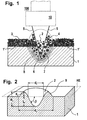
- FIG 1 1 is a cross section through part of a Tool called.
- the surface 1 'of the tool 1 is Substrate for a coating with carbide powder 3, which applied with an organic binder has been.
- the tool itself consists of a commercially available one Cold work steel 1.2601 (standard DIN 17350).
- a commercially available pulse laser system is located above it (Nd: YAG laser) 100 with a focusing lens 10; the emerging laser beam is denoted by 5 and dispersed the carbides 3 in an implantation zone 6. Through the high point energy sublimes part of the Steel 1 and alloyed or is remelted in an edge zone 7. There remains a crater 2, which is dispersed with and alloyed carbide 4 is filled. The transition between the edge zone 7 to the substrate of the tool 1 is 8 denotes and relates to a solid phase, in which only a structural change has taken place.
- FIG. 2 The simplified form of such a manufactured ideal lubrication pocket can be seen in Fig. 2, wherein here the annular edge termination is designated by 9.
- a main level HE which is identical, is also entered with the tool surface in the area of the crater is.
- outer ring diameter with d a the inner ring diameter d i, the maximum depression of the crater with respect to the main plane HE with t K and the elevation with respect to this are shown with h s .
- the total dimension is R t ; the tangential angle characterizing the slope in crater 2 is ⁇ and is generally 15 ° to 45 °.
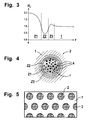
- An examination of the melting process according to FIG. 1 shows the typical layer structure according to FIG. 3, after completion mechanical ablation:
- a remelting zone Z2 which is also was remelted, but is carbide-free.
- the next Layer is a conversion zone Z3, which is in the solid phase is formed by exposure to heat. Located outside the substrate, the tool steel 1.
- the relative hardness is denoted by H v in the ordinate.
- Fig. 5 One created according to the invention with a uniform grid Tool surface is shown in Fig. 5. Depending on the local The distances between the individual are stress Craters 2 varies, but this is done for practical purposes Reasons line by line (in columns).
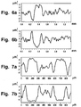
- a tool surface with the above data has an interferometric Profile in the abscissa direction according to Fig. 6a.
- V3A Stain is distilled from 100 parts Water, 100 parts hydrochloric acid (37%), 10 parts nitric acid (65%) and 0.3 parts of commercial "savings” (Dr. Vogels Sparbeize, No. 1830/170014, Wirtz-Buehler GmbH, D-40599 Düsseldorf).
- FIG. 7a and FIG. 7b show the good embossing behavior and the system not just because of its tribological Advantages, but also because of the ideal texturing of the Workpiece for subsequent coatings (body panels etc.) recommend.
- the procedure is based on economic considerations commercially available carbides; but it can also be implant other materials or alloy according to the invention.
Abstract
Description
Die vorliegende Erfindung bezieht sich auf ein Verfahren
nach Patentanspruch 1 und auf eine Schmiertasche nach Anspruch
6 sowie auf eine bevorzugte Anwendung des Verfahrens
nach Anspruch 10.The present invention relates to a method
according to
Ein Verfahren gemäss dem Oberbegriff des Anspruchs 1 wurde
in der PCT/CH99/00451 vorgeschlagen und hat zum Zweck Werkstückoberflächen
unterschiedlicher physikalischer/technischer
und/oder chemischer Eigenschaften zu bilden und den
Verschleiss an hochbeanspruchten Oberflächen zu reduzieren.
Dadurch lassen sich auch die tribologischen Eigenschaften
der Oberflächen günstig beeinflussen.A method according to the preamble of
Verfahren zur Herstellung definierter Mikrostrukturen auf
Werkzeugoberflächen und auf Werkstücken sind seit einigen
Jahren bekannt (u.a. DE -A1- 195 29 429) und finden insbesondere
in Umformprozessen Verwendung. Dabei wird während
der plastischen Umformung eine Abprägung der Textur (Mikrogeometrie)
der Werkzeugoberfläche auf der Werkstückoberfläche
erreicht; diese Abprägung wirkt sich in Bezug auf die
Standzeit der Werkzeuge in Folgeprozessen günstig aus. Eine
Analyse der Funktionen einer gezielt mit Mikrostrukturen
versehenen Oberfläche ergibt folgendes:
Eine mittelbare Strukturierung von Werkstückoberflächen empfiehlt sich vor allem bei hohen Stückzahlen; die notwendige, definierte Struktur im Werkstück setzt in der Regel mehrere Formgebungsschritte voraus, wobei die für jeden Folgeschritt tribologisch geeignete Oberflächenstruktur vorzusehen ist.An indirect structuring of workpiece surfaces is particularly recommended for large quantities; the necessary, defined structure in the workpiece usually sets several shaping steps ahead, the one for each Subsequent step tribologically suitable surface structure is to be provided.
Bekannt sind derartige Verfahren in der Feinblechherstellung, beim Tiefziehen u.a. auch beim reduzierenden Kaltwalzen mit nachfolgendem Nachwalzen. Es hat sich gezeigt, dass sich Strukturen nachteilig auswirken, bei denen die gebildeten Schmiertaschen durch Abprägen eines durch Volumenverlagerung entstandenen erhabenen Strukturanteils entstanden sind. Durch die zwangsläufige Verknüpfung eines erhabenen Strukturanteils mit einer Vertiefung resultiert zwingend eine tribologisch ungünstige Materialumlagerung, die in einer Nachbearbeitung, meist durch einen Schleifvorgang, abgetragen wird. Damit verliert eine solche Schmiertasche ihre Verschleissfestigkeit und ihren Randabschluss. Es können somit nur sehr beschränkt Schmiermittelreserven gebildet werden, die zudem durch dynamischen Vorgänge während des Formgebungsprozesses entweder ausgespült und/oder durch Wegquetschen des Schmierstoffes aus den Zonen höchster Kontaktspannungen entfernt werden.Such methods are known in the production of thin sheets, for deep drawing etc. also with reducing cold rolling with subsequent re-rolling. It has been shown that structures adversely affect the ones that are formed Lubrication pockets by embossing one by volume shift resulting raised structural portion are. By inevitably linking a sublime Structural part with a deepening results inevitably a tribologically unfavorable material rearrangement, which in one Post-processing, usually by grinding becomes. Such a lubrication bag loses their wear resistance and their edge finish. It can thus only very limited lubricant reserves are formed that are also affected by dynamic processes during of the shaping process either rinsed and / or through Squeezing the lubricant out of the zones of highest contact voltages be removed.
Es ist daher Aufgabe der vorliegenden Erfindung Verfahren
zur Erzeugung einer verbesserten, optimierten Schmiertaschengeometrie
zu schaffen, welche folgende Eigenschaften
aufweist:
Diese Aufgabe lässt sich durch ein Prägewerkzeug das nach
dem Verfahren nach den Merkmalen des Anspruchs 1 hergestellt
wurde lösen; die resultierenden Schmiertaschen erfüllen
die Merkmale von Anspruch 6.This task can be done with an embossing tool
the method according to the features of
Der im Patentanspruch 1 erwähnte Eintrag von Karbidpartikeln
kann gemäss PCT/CH99/00451 durch eine vor der thermischen
Behandlung auf die Werkzeugoberfläche aufgetragene
Schlicke, durch mit Karbidpulver belegte Klebstreifen oder
durch Karbidpartikel welche in die Schmelze eingetragen
werden, erfolgen. Letzteres wird bei der Beschichtung von
Metalloberflächen sowie ähnlichen Technologien häufig angewendet
und gilt als an sich bekannte, übliche Methode.The entry of carbide particles mentioned in
Die Menge des Eintrags an Karbidpartikel wird empirisch bestimmt und hat die durch Sublimierverdampfen, Erstarrungsschrumpfen und durch die Plasma-Schockwelle entstehenden Materialverluste in der Werkzeugoberfläche zu kompensieren, d.h. das Niveau der Werkzeugoberfläche - dessen Topographie - soll nach dem lokalen Aufschmelzen möglichst unverändert, zumindest aber reproduzierbar sein und nur im Mikrobereich variieren.The amount of carbide particle entry is determined empirically and has that through sublimation evaporation, solidification shrinking and caused by the plasma shock wave To compensate for material losses in the tool surface, i.e. the level of the tool surface - its topography - should be as unchanged as possible after the local melting, at least be reproducible and only in the micro range vary.
In der zentralen Karbide enthaltenden Zone treten diese in Form von dispergierten Partikeln aber auch als Legierungsbestandteile in Metallkarbiden auf, welche sich während des lokalen Aufschmelzens und Abkühlens bilden.These occur in the central carbide-containing zone Form of dispersed particles but also as alloy components in metal carbides, which develop during the form local melting and cooling.
Charakteristisch für eine mit einem erfindungsgemässen Prägewerkzeug hergestellte Textur ist das Vorhandensein eines vertikal orientierten "Abschlussrings" in der Werkstückoberfläche. Dieser bewirkt eine mechanische Abgrenzung, d.h. eine geschlossene Schmiertasche während der ersten Kontaktphase mit dem, beispielsweise formgebenden Werkzeug.- Dadurch kann ein hydrodynamischer Druckaufbau erfolgen, was die Schmierstoffversorgung aktiviert, selbst dann, wenn noch keine eigentlichen Formschlüsse zwischen Werkzeug und Werkstück erfolgt sind. Aufgrund der resultierenden geringen Kontaktflächen bildet sich ein Leervolumen über der die Schmiertaschen umgebenden Oberfläche, über welches Schmierstoff in die Kontaktzonen hoher Belastung geführt wird.- Dies bewirkt einen, gegenüber einer auf reiner Oberflächenbenetzung beruhenden Schmierung, beträchtlich verstärkten hydrodynamischen Schmierfilm hoher Tragfähigkeit.Characteristic of one with an embossing tool according to the invention manufactured texture is the presence of a vertically oriented "end ring" in the workpiece surface. This causes a mechanical delimitation, i.e. a closed lubrication pocket during the first Contact phase with the shaping tool, for example. This enables a hydrodynamic pressure build-up to take place what activates the lubricant supply, even then, if there is no actual form fit between the tool and workpiece are done. Because of the resulting low An empty volume forms over the contact surfaces the surface surrounding the lubrication pockets, over which Lubricant led into the contact zones of high load - This causes one, compared to one on pure surface wetting based lubrication, considerably reinforced hydrodynamic lubricating film with high load capacity.
Bei einer fortschreitenden Einebnung der Oberfläche ist das "Wegquetschen" von Schmierstoff unvermeidlich, was sich aber durch eine Vergrösserung (Überdimensionierung) des Schmiertaschenvolumens soweit kompensieren lässt, dass beispielsweise der Formgebungsprozess auch nach langer Standzeit, noch ohne grösseren Verschleiss, durchführbar ist.With a progressive leveling of the surface, this is "Squeezing" of lubricant inevitable what is but by enlarging (oversizing) the Lubrication pocket volume can be compensated so far that, for example the shaping process even after a long service life, is still feasible without major wear.
Aufgrund der bisher üblichen Voraussetzung einer annähernden Volumenkonstanz bei den konventionellen Herstellungsverfahren für Schmiertaschen sind bei erfindungsgemäss hergestellten Werkzeugoberflächen geänderte (kleinere) Spiele zwischen den Werkzeugen möglich, d.h. es können auch beim Texturieren von Oberflächen engere Masstoleranzen eingehalten werden.Due to the usual requirement of an approximate Constant volume in conventional manufacturing processes for lubrication pockets are in manufactured according to the invention Tool surfaces changed (smaller) games possible between the tools, i.e. it can also with Texturing of surfaces adhered to closer dimensional tolerances become.
Durch das im Patentanspruch erwähnte lokale thermische Umschmelzen der Werkzeugoberfläche wird eine derart hohe Energie in den Werkstoff (Substrat) eingebracht, dass eine Sublimierverdampfung stattfindet und somit nahezu keine Werkstoffumlagerung erfolgt.- Der gewünschte Randabschluss der Krater ist mehrheitlich mit Metallkarbiden und Legierungsbestandteilen aufgebaut und besitzt eine entsprechend hohe Verschleissfestigkeit, die sich zudem durch die vorbestimmbare Menge an eingetragenem Karbidpulver steuern lässt.By the local thermal remelting mentioned in the claim the tool surface becomes so high Energy introduced into the material (substrate) that a Sublimation evaporation takes place and therefore almost none Material transfer takes place - the desired edge finish the crater is mostly with metal carbides and alloy components built up and has a corresponding high wear resistance, which is also characterized by the predeterminable Control the amount of carbide powder added leaves.
Der Patentanspruch 1 beschreibt das besonders einfach und
auf zahlreichen bekannten Anlagen realisierbare Aufschmelzen
einer mit Karbidpartikeln belegten Oberfläche. The
Überraschenderweise stellt sich nach einem notorisch bekannten, spanlosen Abtragungsvorgang auf der Werkzeugoberfläche - am Ort der Wärmebehandlung - eine Struktur ein, welche hervorragend zur Abprägung geeignet ist und ideale Schmiertaschen in der Werkstückoberfläche erzeugt.Surprisingly, a notoriously known, non-cutting removal process on the tool surface - at the place of heat treatment - a structure, which is ideally suited for stamping and ideal Lubrication pockets created in the workpiece surface.
Die erfindungsgemässe Schmiertasche zeichnet sich durch ihre relativ voluminöse kraterförmige Vertiefung und einen umlaufenden Randabschluss geringer Höhe aus.The lubrication bag according to the invention is characterized by their relatively voluminous crater-shaped depression and one circumferential edge of low height.
In abhängigen Ansprüchen sind bevorzugte Weiterbildungen des Erfindungsgegenstands charakterisiert.Preferred developments are in dependent claims characterized the subject of the invention.
Besonders wirtschaftlich und rationell ist der verfahrensgemässe Einsatz eines gepulsten Nd:YAG-Lasers.The process is particularly economical and efficient Use of a pulsed Nd: YAG laser.
Grundsätzlich lässt sich mittels notorisch bekannter, gekühlter Fokusierlinsen der Brennfleck des Laserstrahls in weiten Grenzen einstellen, so dass auch bei gleicher Strahlleistung kraterförmige Vertiefungen beliebiger Grösse und Randwinkel erzielbar sind.Basically, it can be cooled by means of notoriously known Focusing lens the focal spot of the laser beam in set wide limits so that even with the same Beam power crater-shaped depressions of any size and contact angles are achievable.
Eine sehr einfache und wirtschaftliche Festlegung, und Verfeinerung der erhabenen Teile der Oberfläche, insbesondere deren Abrundung und Glättung erfolgt mittels einer Strahlbearbeitung. Dabei werden gleichzeitig lose oder schlecht haftende Karbid- und/oder Legierungsbestandteile entfernt.A very simple and economical definition and refinement the raised parts of the surface, in particular their rounding and smoothing is done by means of a beam processing. This makes them loose or bad at the same time adhering carbide and / or alloy components removed.
Anlagetechnisch günstig sind mechanische Strahlbearbeitungen, da die entsprechenden Geräte relativ klein sind und sich leicht in den Herstellungsprozess integrieren lassen. Denkbar ist aber auch der Einsatz von anderen Strahlungsquellen sowie von unter hohem Druck beaufschlagten Fluids, aber auch ein Bürsten und damit ein Abschleifen von Zonen geringerer Härte.Mechanical blasting is favorable in terms of plant technology, because the corresponding devices are relatively small and can be easily integrated into the manufacturing process. However, the use of other radiation sources is also conceivable as well as fluids under high pressure, but also brushing and thus sanding off zones lower hardness.
Gleichzeitig lässt sich durch die Strahlbearbeitung der Verschleissgradient am Werkstück und damit dieser auch zwischen dem Werkzeug und dem Werkstück einstellen, in dem die Karbidschicht auf das gewünschte Mass reduziert wird.At the same time, the beam processing enables the Wear gradient on the workpiece and therefore also between the tool and the workpiece in which the Carbide layer is reduced to the desired level.
Je nach Werkzeuggrösse und vorhanden anlagetechnischen Möglichkeiten kann auch eine chemische Abtragung vorteilhaft sein. Selbstverständlich muss das gewählte Abtragungsverfahren an die Härte des Substrats, d.h. der Werkzeugoberfläche angepasst sein, damit sich deren Masse und Oberflächenbeschaffenheit nicht nachteilig verändern; in Frage kommen auch mehrstufige Abtragungsverfahren.Depending on the size of the tool and the available technical facilities chemical ablation can also be beneficial his. Of course, the chosen deduction procedure the hardness of the substrate, i.e. the tool surface be adjusted so that their mass and surface quality do not change adversely; in question there are also multi-stage deduction procedures.
Die ursprüngliche Karbidschicht - vor dem thermischen Aufschmelzen - lässt sich besonders einfach in Form einer Schlicke auf die gewünschten Stellen auf der Werkzeugoberfläche aufbringen; ebenfalls bewährt haben sich mit Karbidpulver beschichtete Klebestreifen.The original carbide layer - before thermal melting - can be particularly easily in the form of a Click on the desired places on the tool surface apply; have also proven themselves with carbide powder coated adhesive strips.
Die eigentliche Ausgestaltung der Schmiertaschen kann in weiten Grenzen variiert werden, was eine Anpassung an die Werkzeuggeometrie, die örtliche Belastung und an das zum Einsatz gelangende Schmiermittel sowie den präsumtiv resultierenden Abrieb erlaubt. Die Form der Schmiertaschen ist nicht auf rotationssymmetrische Krater beschränkt, es können auch längliche Krater gebildet werden, wenn dies tribologisch sinnvoll erscheint. Wichtig sind in jedem Fall Randabschlüsse, welche eine Steigung aufweisen, die aufgrund der üblicherweise relativ hohen Kohäsion von Schmiermitteln verhindern dass diese aus dem Krater gezogen oder gepresst werden.- Aus diesen Kriterien ergeben sich die beanspruchten, bevorzugten Abmessungen die individuell optimierbar sind.The actual design of the lubrication pockets can be found in wide limits are varied, adapting to the Tool geometry, the local load and to the Lubricants used and the presumably resulting Abrasion allowed. The shape of the lubrication pockets is not limited to rotationally symmetrical craters, it can elongated craters are also formed if this is tribological seems reasonable. Are important in any case Edge finishes, which have a slope that due to the usually relatively high cohesion of lubricants prevent them from being pulled out of the crater or - These criteria result in the claimed, preferred dimensions that can be individually optimized are.
Bevorzugte Steigungwinkel für die Randabschlüsse sind in weiteren abhängigen Ansprüchen aufgezeigt, wobei auf flüssige Schmierstoffe mittlerer Viskosität abgestellt ist.Preferred slope angles for the edge closures are in further dependent claims are shown, with liquid Medium viscosity lubricants is turned off.
Verfahrensgemäss hergestellte Prägewalzen (= Werkzeuge) für die Feinblechherstellung bilden zusammen mit dem zu walzenden Blech (= Werkstück) bereits während des Walzvorgangs Schmiertaschen, die sich günstig auf den Verschleiss der Prägewalze auswirken. In nachfolgenden Umformprozessen gewährleisten die im Blech abgeprägten Schmiertaschen höhere Standzeiten der meist sehr kostspieligen Werkzeugformen. Wenn die erzielte Textur regelmässig auf der Blechoberfläche verteilt wird, dient sie gleichzeitig als idealer Haftgrund für spätere Beschichtungen, was besonders im Karosseriebau erwünscht ist.Embossing rollers (= tools) for form the sheet metal production together with that to be rolled Sheet (= workpiece) already during the rolling process Lubrication pockets, which are favorable to the wear of the Impact embossing roller. Ensure in subsequent forming processes the lubrication pockets embossed in the sheet metal are higher Tool life of the usually very expensive tool forms. If the texture achieved regularly on the sheet surface distributed, it also serves as an ideal adhesive base for later coatings, which is particularly important in body construction is desired.
Nachfolgend werden anhand von Zeichnungen Ausführungsbeispiele des Erfindungsgegenstands näher erläutert. Es zeigen:
- Fig. 1
- eine schematische Schnittdarstellung, welche die Karbidschicht nach der thermischen Bearbeitung der Werkzeugoberfläche aufzeigt, wobei der zur Bearbeitung benutzte Laser und der Strahlwinkel angedeutet sind,
- Fig. 2
- eine charakteristische Form eines einzelnen, durch Abprägen mit einem verfahrensgemäss hergestellten Werkzeug erzeugten Kraters, mit eingetragener Vermassung,
- Fig. 3
- in Funktion des Radius r feststellbare Zonen, die durch die thermische Bearbeitung entstanden sind, in normierter, vergrösserter Darstellung,
- Fig. 4
- die Zonen nach Fig. 2 in einer Draufsicht auf den Krater,
- Fig. 5
- eine mögliche deterministische Anordnung der
thermisch implantierten Arbeitspunkte nach Fig. 1
bis 3, in einer vereinfachten, ausschnittweisen Vergrösserung auf einer Werkzeugoberfläche , - Fig. 6a
- ine in Abszisse-Richtung interferometrisch vermessene, reale Werkzeugoberflächenstruktur,
- Fig. 6b
- die Abprägung der Oberflächenstruktur Fig. 6a im Werkstück,
- Fig. 7a
- eine in Ordinate-Richtung interferometrisch vermessene, reale Werkzeugoberflächenstruktur und
- Fig. 7b
- die Abprägung der Oberflächenstruktur Fig. 6a im Werkstück.
- Fig. 1
- 2 shows a schematic sectional illustration which shows the carbide layer after the thermal processing of the tool surface, the laser used for the processing and the beam angle being indicated,
- Fig. 2
- a characteristic shape of a single crater, produced by stamping with a tool manufactured in accordance with the method, with registered dimensions,
- Fig. 3
- Zones ascertainable as a function of the radius r, which have arisen as a result of thermal processing, in a standardized, enlarged representation,
- Fig. 4
- 2 in a plan view of the crater,
- Fig. 5
- 1 a possible deterministic arrangement of the thermally implanted working points according to FIGS. 1 to 3, in a simplified, partial enlargement on a tool surface,
- Fig. 6a
- a real tool surface structure measured interferometrically in the abscissa direction,
- Fig. 6b
- the embossing of the surface structure Fig. 6a in the workpiece,
- Fig. 7a
- a real tool surface structure measured interferometrically in the ordinate direction and
- Fig. 7b
- the embossing of the surface structure Fig. 6a in the workpiece.
In Figur 1 ist mit 1 ein Querschnitt durch ein Teil eines
Werkzeugs bezeichnet. Die Oberfläche 1' des Werkzeugs 1 ist
Substrat für eine Beschichtung mit Karbidpulver 3, welches
mit einem organischen Bindemittel versehen aufgetragen
wurde. Das Werkzeug selbst besteht aus einem handelsüblichen
Kaltarbeitsstahl 1.2601 (Norm DIN 17350). In Figure 1, 1 is a cross section through part of a
Tool called. The surface 1 'of the
Darüber befindet sich eine handelsübliche Impulslaser-Anlage
(Nd:YAG-Laser) 100 mit einer Fokusierlinse 10; der
austretenden Laserstrahl ist mit 5 bezeichnet und dispergiert
die Karbide 3 in einer Implantier-Zone 6. Durch die
hohe punktuell auftreffende Energie sublimiert ein Teil des
Stahls 1 und legiert bzw. wird in einer Randzone 7 umgeschmolzen.
Es verbleibt ein Krater 2, der mit dispergierten
und legierten Karbiden 4 ausgefüllt ist. Der Übergang zwischen
der Randzone 7 zum Substrat des Werkzeugs 1 ist mit 8
bezeichnet und betrifft eine Festphase, in welcher lediglich
eine Gefügeumwandlung statt gefunden hat.A commercially available pulse laser system is located above it
(Nd: YAG laser) 100 with a focusing
Wird nun eine solcher Art vorbereitete Werkzeugoberfläche 1' einem Abtragungsvorgang beispielsweise durch Sandstrahlen unterzogen, so verbleiben die harten, Karbide enthaltenden Schichten nahezu unverändert, während die weicheren Umschmelzonen abgetragen werden und ringförmige Ausnehmungen bilden. Durch Abprägen einer solchen Topographie lassen sich Schmiertaschen bilden.Now such a kind of prepared tool surface 1 'a removal process, for example by sandblasting subjected, so remain the hard, containing carbides Layers almost unchanged, while the softer ones Remelting zones are removed and annular recesses form. By stamping such a topography grease pockets form.
Die vereinfacht dargestellte Form einer derart hergestellten idealen Schmiertasche ist in Fig. 2 zu sehen, wobei hier der ringförmige Randabschluss mit 9 bezeichnet ist. Ebenfalls eingetragen ist eine Hauptebene HE, welche identisch mit der Werkzeugoberfläche im Bereich des Kraters ist.The simplified form of such a manufactured ideal lubrication pocket can be seen in Fig. 2, wherein here the annular edge termination is designated by 9. A main level HE, which is identical, is also entered with the tool surface in the area of the crater is.
Ferner sind der äussere Ringdurchmesser mit da, der innere
Ringdurchmesser di die maximale Vertiefung des Kraters gegenüber
der Hauptebene HE mit tK und die Überhöhung gegenüber
dieser mit hs eingezeichnet. Das Gesamtmass beträgt Rt;
der die Flankensteigung im Krater 2 charakterisierende Tangentialwinkel
ist β und beträgt in der Regel 15° bis 45°. Furthermore, the outer ring diameter with d a , the inner ring diameter d i, the maximum depression of the crater with respect to the main plane HE with t K and the elevation with respect to this are shown with h s . The total dimension is R t ; the tangential angle characterizing the slope in
Eine Untersuchung der gemäss Fig. 1 erfolgten Aufschmelzung zeigt den nach Fig. 3 typischen Schichtaufbau, nach erfolgter mechanischer Abtragung:An examination of the melting process according to FIG. 1 shows the typical layer structure according to FIG. 3, after completion mechanical ablation:
Vom Zentrum des Kraters 2 in radialer Richtung r, siehe
Fig. 4, trifft man auf die erste Schicht Z1, die dispergierte/legierte
Schicht welche durch die thermisch erfolgte
Flüssigphasenbearbeitung entstand. Danach folgt eine etwas
dünnere Schicht, eine Umschmelzone Z2, die zwar ebenfalls
umgeschmolzen wurde, aber karbidfrei ist. Die nächste
Schicht ist eine Umwandlungszone Z3, welche in der Festphase
durch Wärmeeinwirkung gebildet ist. Aussen befindet
sich das Substrat, der Werkzeugstahl 1.From the center of
Die relative Härte ist in der Ordinate mit Hv bezeichnet.The relative hardness is denoted by H v in the ordinate.
Eine mit gleichmässigem Raster erfindungsgemäss erstellte
Werkzeugoberfläche ist in Fig. 5 dargestellt. Je nach örtlicher
Belastung werden die Abstände zwischen den einzelnen
Kratern 2 variiert, doch erfolgt dies aus praktischen
Gründen linienweise (in Kolonnen).One created according to the invention with a uniform grid
Tool surface is shown in Fig. 5. Depending on the local
The distances between the individual are
Am realisierten Werkzeug wurden folgende beispielsweisen
charakteristischen Daten durch eine interferometrische
Oberflächenmessung gewonnen:
Es wurden folgende Laserparameter angewendet:
Eine Werkzeugoberfläche mit den obigen Daten weist ein interferometrisches Profil in Abszisse-Richtung gemäss Fig. 6a auf.A tool surface with the above data has an interferometric Profile in the abscissa direction according to Fig. 6a.
Besonders bewährt hat sich für den Abtragungsvorgang ein Glasstrahlen mit handelsüblichen, kugelförmigen Glasperlen von 25 - 50 µm Durchmesser unter einem Druck von 4,0 bar.Has proven particularly useful for the removal process Glass rays with commercially available, spherical glass beads of 25 - 50 µm diameter under a pressure of 4.0 bar.
Ebenfalls geeignet ist hierfür ein Ätzmittel unter der Bezeichnung "V3A Beize", welches aus 100 Teilen destilliertem Wasser, 100 Teilen Salzsäure (37 %), 10 Teilen Salpetersäure (65 %) und 0,3 Teilen handelsüblicher "Sparbeize" (Dr. Vogels Sparbeize, Nr. 1830/170014, Wirtz-Buehler GmbH, D-40599 Düsseldorf) besteht.An etchant under the name is also suitable for this "V3A Stain", which is distilled from 100 parts Water, 100 parts hydrochloric acid (37%), 10 parts nitric acid (65%) and 0.3 parts of commercial "savings" (Dr. Vogels Sparbeize, No. 1830/170014, Wirtz-Buehler GmbH, D-40599 Düsseldorf).
Die mit einem Druck von 25 bar erzeugte Abprägung in einem Aluminiumwerkstück (99,5 % Al) zeigt das zu Fig. 6a inverse Profil gemäss Fig. 6b.The impression created with a pressure of 25 bar in one Aluminum workpiece (99.5% Al) shows this inverse to Fig. 6a Profile according to Fig. 6b.
Analog sind die Aufzeichnungen in Ordinate-Richtung Fig. 7a und Fig. 7b, welche wiederum das gute Abprägeverhalten zeigen und das System nicht nur wegen seiner tribologischen Vorteile, sondern auch wegen der idealen Texturierung des Werkstücks für nachfolgende Beschichtungen (Karosseriebleche etc.) empfehlen. The recordings in the ordinate direction are analogous to FIG. 7a and FIG. 7b, which in turn show the good embossing behavior and the system not just because of its tribological Advantages, but also because of the ideal texturing of the Workpiece for subsequent coatings (body panels etc.) recommend.
Die anhand eines Werkzeugs und eines zu bearbeitenden Werkstücks geführten Betrachtungen lassen sich selbstverständlich auch auf Gleitflächen übertragen, bei denen in einer - oder bei kürzeren Gleitwegen - wechselseitig in beiden Gleitflächen erfindungsgemässe Schmiertasche an Orten hoher Belastung vorgesehen sind.Using a tool and a workpiece to be machined guided considerations can be taken for granted also transferred to sliding surfaces in which - or with shorter glide paths - alternately in both Sliding surfaces lubrication pocket according to the invention in places higher Load are provided.
Aus wirtschaftlichen Überlegungen ist das Verfahren auf handelsübliche Karbide bezogen; es lassen sich aber auch andere Werkstoffe implantieren bzw. erfindungsgemäss zulegieren.The procedure is based on economic considerations commercially available carbides; but it can also be implant other materials or alloy according to the invention.
- 11
- Werkzeug (Substrat); KaltarbeitsstahlTool (substrate); Cold work steel
- 1'1'
- WerkzeugoberflächeTool surface
- 22nd
- Krater / VertiefungCrater / depression
- 33rd
- KarbidpulverCarbide powder
- 44th
- dispergierte Metallkarbidedispersed metal carbides
- 55
- Laserstrahl (fokusiert)Laser beam (focused)
- 66
- (Karbid-) implantierte Zone(Carbide) implanted zone
- 77
- UmschmelzoneRemelting zone
- 88th
- Festphase mit GefügeumwandlungSolid phase with structural transformation
- 99
- RandabschlussEdging
- 1010th
- Fokusierlinse (gekühlt)Focusing lens (cooled)
- 100100
- Impulslaser-Anlage (Nd:YAG-Laser)Pulse laser system (Nd: YAG laser)
- HEHE
- Werkstückoberfläche (Hauptebene)Workpiece surface (main plane)
- da d a
- max. Durchmesser RandabschlussMax. Edge edge diameter
- di d i
- innerer Durchmesser Randabschlussinner diameter edge finish
- tK t K
- max. VertiefungMax. deepening
- hshs
- ÜberhöhungCant
- Hv H v
- relative Härterelative hardness
- ββ
- Tangentialwinkel (Flankensteigung)Tangential angle (slope)
- rr
- Radius (Krater)Radius (crater)
- Rt R t
- Fülltiefe SchmiermittelFilling depth lubricant
- Z1Z1
- dispergierte/legierte Schichtdispersed / alloyed layer
- Z2Z2
- UmschmelzoneRemelting zone
- Z3Z3
- UmwandlungszoneTransformation zone
Claims (10)
Priority Applications (4)
| Application Number | Priority Date | Filing Date | Title |
|---|---|---|---|
| EP00810237A EP1136574A1 (en) | 2000-03-21 | 2000-03-21 | Process for manufacturing embossing tools and their uses |
| EP01911329A EP1268864A1 (en) | 2000-03-21 | 2001-03-21 | Production of an embossing tool and use of the same |
| AU2001240411A AU2001240411A1 (en) | 2000-03-21 | 2001-03-21 | Production of an embossing tool and use of the same |
| PCT/CH2001/000180 WO2001071048A1 (en) | 2000-03-21 | 2001-03-21 | Production of an embossing tool and use of the same |
Applications Claiming Priority (1)
| Application Number | Priority Date | Filing Date | Title |
|---|---|---|---|
| EP00810237A EP1136574A1 (en) | 2000-03-21 | 2000-03-21 | Process for manufacturing embossing tools and their uses |
Publications (1)
| Publication Number | Publication Date |
|---|---|
| EP1136574A1 true EP1136574A1 (en) | 2001-09-26 |
Family
ID=8174607
Family Applications (2)
| Application Number | Title | Priority Date | Filing Date |
|---|---|---|---|
| EP00810237A Withdrawn EP1136574A1 (en) | 2000-03-21 | 2000-03-21 | Process for manufacturing embossing tools and their uses |
| EP01911329A Withdrawn EP1268864A1 (en) | 2000-03-21 | 2001-03-21 | Production of an embossing tool and use of the same |
Family Applications After (1)
| Application Number | Title | Priority Date | Filing Date |
|---|---|---|---|
| EP01911329A Withdrawn EP1268864A1 (en) | 2000-03-21 | 2001-03-21 | Production of an embossing tool and use of the same |
Country Status (3)
| Country | Link |
|---|---|
| EP (2) | EP1136574A1 (en) |
| AU (1) | AU2001240411A1 (en) |
| WO (1) | WO2001071048A1 (en) |
Cited By (4)
| Publication number | Priority date | Publication date | Assignee | Title |
|---|---|---|---|---|
| EP3438476A1 (en) * | 2017-07-31 | 2019-02-06 | Daido Metal Company Ltd. | Half bearing and sliding bearing |
| EP3486508A1 (en) * | 2017-11-17 | 2019-05-22 | Daido Metal Company Ltd. | Half bearing and sliding bearing |
| WO2021069247A1 (en) * | 2019-10-10 | 2021-04-15 | Thyssenkrupp Steel Europe Ag | Sheet steel having a deterministic surface structure |
| US20220154769A1 (en) * | 2020-11-19 | 2022-05-19 | Daido Metal Company Ltd. | Sliding member |
Families Citing this family (2)
| Publication number | Priority date | Publication date | Assignee | Title |
|---|---|---|---|---|
| DE102010028183B4 (en) | 2010-04-26 | 2017-09-14 | Hochschule Esslingen | Forming tool and method for machining the surface of a forming tool |
| WO2017144407A1 (en) | 2016-02-23 | 2017-08-31 | Salzgitter Flachstahl Gmbh | Roller, in particular skin pass roller, and skin passed flat product |
Citations (6)
| Publication number | Priority date | Publication date | Assignee | Title |
|---|---|---|---|---|
| BE901055A (en) * | 1984-11-14 | 1985-05-14 | Centre Rech Metallurgique | Surface treatment of cold rolling cylinder - by coating with hardening component prior to exposing to laser beam treatment |
| EP0230633A2 (en) * | 1985-12-20 | 1987-08-05 | Union Carbide Corporation | Friction roll with wear-resistant surface |
| EP0253366A1 (en) * | 1986-07-14 | 1988-01-20 | Kawasaki Steel Corporation | Apparatus for making a work roll with dulled surface having geometrically patterned uneven dulled sections for temper rolling |
| JPH0489122A (en) * | 1990-07-30 | 1992-03-23 | Daido Steel Co Ltd | Production of dull roll for rolling |
| WO1992005909A1 (en) * | 1990-10-05 | 1992-04-16 | Linotype-Hell Ag | Process and device for manufacturing a texturing roller |
| DE4211197A1 (en) * | 1992-04-03 | 1993-10-07 | Allgaier Werke Kg | Skin pass rolls texturing for surface topography formation - using chemical etching engraving and increasing depth of texture by grinding, for improved tribology |
-
2000
- 2000-03-21 EP EP00810237A patent/EP1136574A1/en not_active Withdrawn
-
2001
- 2001-03-21 WO PCT/CH2001/000180 patent/WO2001071048A1/en not_active Application Discontinuation
- 2001-03-21 AU AU2001240411A patent/AU2001240411A1/en not_active Abandoned
- 2001-03-21 EP EP01911329A patent/EP1268864A1/en not_active Withdrawn
Patent Citations (6)
| Publication number | Priority date | Publication date | Assignee | Title |
|---|---|---|---|---|
| BE901055A (en) * | 1984-11-14 | 1985-05-14 | Centre Rech Metallurgique | Surface treatment of cold rolling cylinder - by coating with hardening component prior to exposing to laser beam treatment |
| EP0230633A2 (en) * | 1985-12-20 | 1987-08-05 | Union Carbide Corporation | Friction roll with wear-resistant surface |
| EP0253366A1 (en) * | 1986-07-14 | 1988-01-20 | Kawasaki Steel Corporation | Apparatus for making a work roll with dulled surface having geometrically patterned uneven dulled sections for temper rolling |
| JPH0489122A (en) * | 1990-07-30 | 1992-03-23 | Daido Steel Co Ltd | Production of dull roll for rolling |
| WO1992005909A1 (en) * | 1990-10-05 | 1992-04-16 | Linotype-Hell Ag | Process and device for manufacturing a texturing roller |
| DE4211197A1 (en) * | 1992-04-03 | 1993-10-07 | Allgaier Werke Kg | Skin pass rolls texturing for surface topography formation - using chemical etching engraving and increasing depth of texture by grinding, for improved tribology |
Non-Patent Citations (1)
| Title |
|---|
| PATENT ABSTRACTS OF JAPAN vol. 016, no. 314 (M - 1278) 9 July 1992 (1992-07-09) * |
Cited By (5)
| Publication number | Priority date | Publication date | Assignee | Title |
|---|---|---|---|---|
| EP3438476A1 (en) * | 2017-07-31 | 2019-02-06 | Daido Metal Company Ltd. | Half bearing and sliding bearing |
| EP3486508A1 (en) * | 2017-11-17 | 2019-05-22 | Daido Metal Company Ltd. | Half bearing and sliding bearing |
| WO2021069247A1 (en) * | 2019-10-10 | 2021-04-15 | Thyssenkrupp Steel Europe Ag | Sheet steel having a deterministic surface structure |
| US20220154769A1 (en) * | 2020-11-19 | 2022-05-19 | Daido Metal Company Ltd. | Sliding member |
| US11614122B2 (en) * | 2020-11-19 | 2023-03-28 | Daido Metal Company Ltd | Sliding member |
Also Published As
| Publication number | Publication date |
|---|---|
| WO2001071048A1 (en) | 2001-09-27 |
| AU2001240411A1 (en) | 2001-10-03 |
| EP1268864A1 (en) | 2003-01-02 |
Similar Documents
| Publication | Publication Date | Title |
|---|---|---|
| EP0858519B1 (en) | Method of producing a sliding surface on a metal workpiece | |
| DE19915038A1 (en) | Light metal cylinder block, method for its production and device for carrying out the method | |
| WO2003091474A1 (en) | Structured coating system | |
| DE19824310C1 (en) | Bearing surface for metal bearing | |
| EP0770698B2 (en) | Process for manufacture of a sliding surface on a metallic workpiece | |
| DE10355685B4 (en) | Workpiece with a tribologically stressable surface designed as a cylinder and method for the production thereof | |
| EP1136574A1 (en) | Process for manufacturing embossing tools and their uses | |
| EP3685062B1 (en) | Method for producing a bearing component and a bearing component | |
| EP4041467B1 (en) | Sheet steel having a deterministic surface structure and method for manufacturing such steel sheet | |
| DE102011109071A1 (en) | Pipe Forging Process with Urformed Hollow Block | |
| DE4112614C2 (en) | Mandrel for cold and / or hot forming of metallic goods and process for its production | |
| WO2017144407A1 (en) | Roller, in particular skin pass roller, and skin passed flat product | |
| EP0761324A1 (en) | Metal sheet, mill roll for the manufacture of metal sheet, method of texturing the surface of the mill roll and its use | |
| EP1117846B1 (en) | Method for changing the properties of the surfaces of work pieces | |
| EP0662024B1 (en) | Tool for working the surfaces of components | |
| DE102016001774A1 (en) | Process for thermal coating and component | |
| EP0662161B1 (en) | Tool for working the surfaces of components, and a substrate material for such a tool | |
| WO2023006449A1 (en) | Metal sheet having a deterministic surface structure | |
| DE19724661C2 (en) | Process for producing a toothed gear part | |
| AT514799B1 (en) | bearings | |
| DE102011109059A1 (en) | Method for extrusion of block e.g. chrome-plated steel block, of central mandrel for manufacturing seamless pipe, involves introducing block into extruding device, pressing block over mandrel, and fixing mandrel against die during pressing | |
| DE102022209965A1 (en) | Method for producing or preparing a brake disc for a vehicle and brake disc | |
| EP2554292A1 (en) | Conduit element with surface structure and method for production and use of such a conduit element | |
| WO2017207633A1 (en) | Cylinder, method for finishing a cylinder, reciprocating piston system and use of a reciprocating piston system | |
| DE1596967B2 (en) | Process for the production of a glass-metal composite on a non-porous metal carrier with a fine-grained material embedded on the surface |
Legal Events
| Date | Code | Title | Description |
|---|---|---|---|
| PUAI | Public reference made under article 153(3) epc to a published international application that has entered the european phase |
Free format text: ORIGINAL CODE: 0009012 |
|
| AK | Designated contracting states |
Kind code of ref document: A1 Designated state(s): AT BE CH CY DE DK ES FI FR GB GR IE IT LI LU MC NL PT SE |
|
| AX | Request for extension of the european patent |
Free format text: AL;LT;LV;MK;RO;SI |
|
| AKX | Designation fees paid | ||
| REG | Reference to a national code |
Ref country code: DE Ref legal event code: 8566 |
|
| STAA | Information on the status of an ep patent application or granted ep patent |
Free format text: STATUS: THE APPLICATION IS DEEMED TO BE WITHDRAWN |
|
| 18D | Application deemed to be withdrawn |
Effective date: 20020327 |