EP1136207A1 - Stapler - Google Patents
Stapler Download PDFInfo
- Publication number
- EP1136207A1 EP1136207A1 EP01250106A EP01250106A EP1136207A1 EP 1136207 A1 EP1136207 A1 EP 1136207A1 EP 01250106 A EP01250106 A EP 01250106A EP 01250106 A EP01250106 A EP 01250106A EP 1136207 A1 EP1136207 A1 EP 1136207A1
- Authority
- EP
- European Patent Office
- Prior art keywords
- stapler
- sheets
- pile
- photo sensor
- disposed
- Prior art date
- Legal status (The legal status is an assumption and is not a legal conclusion. Google has not performed a legal analysis and makes no representation as to the accuracy of the status listed.)
- Granted
Links
- 239000013307 optical fiber Substances 0.000 claims description 18
- 238000001514 detection method Methods 0.000 abstract description 4
- 206010016275 Fear Diseases 0.000 abstract description 2
- WABPQHHGFIMREM-UHFFFAOYSA-N lead(0) Chemical compound [Pb] WABPQHHGFIMREM-UHFFFAOYSA-N 0.000 description 8
- 238000012805 post-processing Methods 0.000 description 8
- 238000007599 discharging Methods 0.000 description 2
- 238000010420 art technique Methods 0.000 description 1
- 239000000463 material Substances 0.000 description 1
- 238000000034 method Methods 0.000 description 1
- 230000000149 penetrating effect Effects 0.000 description 1
- 230000001012 protector Effects 0.000 description 1
- 238000002310 reflectometry Methods 0.000 description 1
Images




Classifications
-
- B—PERFORMING OPERATIONS; TRANSPORTING
- B27—WORKING OR PRESERVING WOOD OR SIMILAR MATERIAL; NAILING OR STAPLING MACHINES IN GENERAL
- B27F—DOVETAILED WORK; TENONS; SLOTTING MACHINES FOR WOOD OR SIMILAR MATERIAL; NAILING OR STAPLING MACHINES
- B27F7/00—Nailing or stapling; Nailed or stapled work
- B27F7/17—Stapling machines
- B27F7/19—Stapling machines with provision for bending the ends of the staples on to the work
Definitions
- the present invention relates to a stapler which is disposed to a copying machine and so on.
- a motor driven stapler which comprises, a driving out portion from which a stapler is driven out, a table which forwardly and backwardly reciprocates and a clincher which is disposed on the table.
- a pile of sheets to be bundled is put and held between the driving out portion and the table when the table forwardly moves, and at the same time a stapler is driven out from the driving out portion against the put and held pile of sheets, then the front end portions which penetrate through the pile of sheets are clinched by the clincher.
- a photo sensor of reflecting type is disposed for detection if the pile of sheets is put on the table.
- the photo sensor gives an order for the table to forwardly move and to drive out the stapler from the driving out portion by the driver when it detects the pile of sheets, and prevents useless driving out.
- the photo sensor is disposed in the table and a lead wire for the photo sensor is compelled extending and loosening in every reciprocal movement of the table and the lead wire must be given a loosed portion. Due to this fact, a problem arises that the lead wire is torn when it touches with a corner of the stapler body unless it is not covered with protector to protect the loosening portion, and it makes the regarding portion bombastic.
- the object of the invention is to provide a stapler in which there are no fears for a cutting of the lead wire or need for loosed part of the lead wire of photo sensor for detection of sheets to be bundled.
- a stapler comprising, a driving out portion from which a stapler is driven out; a table which forwardly and backwardly reciprocates; and a clincher which is disposed on said table so as to put and hold a pile of sheets to be bundled between itself and said driving out portion when said table forwardly moves and at the same time a stapler is driven out from the driving out portion against the pile of sheets, and to clinch the front end portions of the staple which penetrate through the pile of sheets, said stapler characterized in that a photo sensor is disposed in the other side of said table to said driving out portion; and one or more through holes are arranged in said table in order to guide the emitted light beam from a light emission portion of said photo sensor to the pile of sheets and to guide the reflected light beam from a
- reference numeral 10 denotes a post processing apparatus disposed to a body of copying machine 11.
- an upside down type stapler 12 is disposed for binding a pile of printed sheet which is discharged from the copying machine body 11 with the surface of copied side down.
- another upside down type stapler 20 is also provided on the top surface of post processing apparatus 10.
- a stapler body 40 of the stapler 20 (Refer to Fig. 2 to Fig. 4) has quite the same structure to that of the stapler body of stapler 12 (not shown) because the same kind of stapler is employed.
- the stapler 20 comprises a base plate 21 which is fixed on a top board 13 of the post processing apparatus 10, a bracket 30 which is rotatably attached on the base plate 21, a stapler body 40 which is fixed on the bracket 30 and a cartridge 60 (Refer to Fig. 7) which is removably loaded to the stapler body 40.
- the base plate 21 has a base board portion 22 which is fixed by screws N1 on the top board 13 of post processing apparatus 10, and plates 23, 23 are formed which are standing from both ends of the base board portion 22.
- the plate 23 is formed to have an U-shaped cross section and having support pillar board portion 24 and arm board portion 25 which is extending from upper portion of the support pillar board portion 24 to frontward (leftward in Fig. 2).
- the bracket 30 has a flat board portion 31 which is fixed by screws N2 on bottom wall portion 41A of a case 41 of the stapler body 40, and attachment piece 32, 32 are formed to hang over from both ends of the flat board portion 31.
- Respective lower portions 32K of attachment pieces 32 are supported by a shaft 34 at the front end portion of arm board portion 25 of the base plate 21, and they are rotatable around the shaft 34.
- the stapler body 40 is attached to the base plate 21 in order to turn around the shaft 34, and to be in a posture of downside up.
- the stapler body 40 is arranged to be fixed by L-shaped a stopper (fixing means) 70 which is made of magnet on the position shown in Fig. 2 to Fig. 4.
- the stopper 70 is attached to the base board portion 22 of base plate 21, and magnetically attracts the stapler body 40 facing to contact together with a top portion of support board 54, which is explained later and to fix the stapler body 40.
- a micro switch (detecting means) 39 is arranged to detect the presence and fixing of the stapler body.
- the micro switch 39 is disposed at the inside portion of arm board portion 25 of the base plate 21, it is arranged to be turned on by a concave portion 32A of the attachment piece 32 of bracket 30, by this turning on the presence and fixing of stapler body 40 is detected.
- the reference numeral 36 denotes a support plate on which a pile of sheets T to be bundled is put
- the reference numeral 37 denotes a cover which is attached at upward of the support plate 36, and is fixed on the support plate 36 through a support portion which is not shown.
- a driving mechanism (not shown) which drives sheet of staples (not shown) stored and piled in a cartridge 60 to a driving out portion 40A, a driver (not shown) which forwardly and backwardly reciprocates to drive out the staple from the driving out portion 40A, and a table 42 having a clincher (not shown) which clinches the front end portions of driven out staple.
- the cartridge 60 is disposed over the table 42 and the table 42 is disposed under the cartridge 60, then the staple is driven out from upper side to lower side of the table 42.
- Table 42 is arranged to be reciprocated upwardly and downwardly by rotational movement of a link member 43 around a shaft 44.
- a roller 45 is disposed in upper portion of the link member 43, and a cam which is not shown in the figure, is contacting with the roller 46, then the link member 43 is arranged to rotate around the shaft 44 by the rotational movement of the cam.
- An opening 46 is formed on the upper surface of table 42 as shown in Fig. 5, into which legs of staple are inserted after penetrating the pile of sheets T to be bundled, and the clincher (not shown) is disposed under the opening 46, by which the legs of staple are clinched.
- a concave portion 47 is formed at the back of opening 46 on the upper surface of table 42 and two through holes 48, 48 are formed in bottom portion 47A of the concave portion 47, and optical fibers 49A, 49B are disposed in the through holes 48, 48.
- a photo sensor 50 is disposed at lower part of the table 42 for detecting if a pile of sheets T is put on the table 42 or not.
- This photo sensor 50 consists of light emission diode (light emission portion) 51 and light receiving diode (light receiving portion) 52, the light emission diode 51 is arranged to confront with a lower end of the optical fiber 49A, and the light receiving diode 52 is arranged to confront with a lower end of the optical fiber 49B.
- the photo sensor 50 is attached to a support board 54 which is formed so as to project forwardly from a front end of the top board 41B of case 41 of the stapler body 40.
- Guide pins 55, 55 are arranged to stand and guide the pile of sheets T as shown in Fig. 6, and the guide pins 55, 55 are located in the positions that the front ends of guide pins are contacting from outside with an extending line of a common tangential line of back ends of the through hole 48 and 48 so that a distance between the guide pins is much larger than that of between the through holes. They are arranged when a pile of sheets T to be bundled is inserted and contacts with both guide pins as shown by the dotted broken line or the double dotted broken line, so that he top surfaces of optical fibers 49A and 49B of through holes 48 and 48 are covered with the sheets and confronts with the bottom surface of the pile of sheets T.
- a copied paper which is processed by the copying machine 11 is discharged to the post processing apparatus 10 with the copied surface down.
- the pile of sheets is bundled by stapler 12 as usual in the prior art technique and it goes to be discharged at the discharging tray 14.
- the copied paper is discharged at the discharging tray 14 with the copied surface down.
- the desired some of copied papers are put on the support plate 36 with their copied surface up and inserted so as to contact with both guide pins 55 and 55 as shown in Fig. 6 (B) by the dotted broken line or the double dotted broken line.
- a light emission diode 51 of the photo sensor 50 is lighted and the light beam is projected upward through the optical fiber 49A in the table 42 from the top end of optical fiber 49A.
- the projected light beam from the top end of optical fiber 49A is reflected by outer surface of the pile of sheets T and enters back to the optical fiber 49B in the table 42.
- the entered light to the optical fiber 49B is projected from the bottom end of optical fiber 49B and it is received by a light receiving diode 52 of the photo sensor 50.
- the micro switch When the light receiving diode 52 receives the light, the micro switch is turned on, and a control circuit which is not shown in the figure, judges that a pilc of sheets T to be bundled is surely put on the support plate 36, then it makes an order to start a motor (not shown) driving.
- the table 42 goes up by this driving of motor in order for pile of sheets T to be put and held between the table 42 and the driving out portion 40A. Then a staple is driven out from the driving out portion 40A and the legs of staple penetrate through the pile of sheets T and the legs of staple are clinched by the clincher arranged on the table 42, thus the pile of sheets is bundled by the stapler.
- the table 42 goes down and returns to its home position after whole process has been completed.
- the support board 54 of stapler body 40 is detached from the stopper 70 and the stapler body 40 is turned around in counter clockwise with enforcing stapler body 40 and the upper cover 35 to turn counter clockwise by handling operation at the convex portion 35A of upper cover 35 as shown in Fig. 7.
- the stapler body 40 takes a posture upside down. By this motion the stapler body 40 returns to be normal position.
- the exchange of cartridge 60 is easily attained by inserting slantwise the cartridge 60 to downward into stapler body 40.
- the stapler body 40 is turned again reverse to the above, in clockwise with the upper cover 35 in order to be in the position shown in Fig. 2 to Fig. 4.
- the pile of sheets T can be bundled with its copied surface up, and the loading of cartridge 60 can be easily achieved by turning the stapler body 40. Further, because the same upside down positioned type model of stapler is used for both of the stapler body 40 and stapler body 12, reduction of material cost is achieved, and the same type of stapler and the same way to bundle is used because the same type of cartridge is employed, the appearance of pile of sheets bundled by stapler 12 and by stapler 20 seems to be same and it gives a good feeling.
- the light is emitted through the optical fiber 49A in the table 42 to the pile of sheets T, the light which is emitted from the light emission diode 51 of photo sensor 50, can be projected on the surface of pile of sheets T without being weakened.
- the structure is arranged to receive the reflected light from pile of sheets T through the optical fiber 49B in the table 42 by the light receiving diode 52 of photo sensor 50, the reflected light from the pile of sheets T can be received without being weakened.
- two optical fiber 49A and 49B are disposed in the table 42, however, one optical fiber can be employed when the diameter of optical fiber is large. Further, the optical fiber 49A and 49B can be omitted when the power of light from the light emission diode 51 is large and at the same time the reflectivity of pile of sheets T for light is high.
Landscapes
- Engineering & Computer Science (AREA)
- Mechanical Engineering (AREA)
- Life Sciences & Earth Sciences (AREA)
- Forests & Forestry (AREA)
- Portable Nailing Machines And Staplers (AREA)
- Dovetailed Work, And Nailing Machines And Stapling Machines For Wood (AREA)
- Folding Of Thin Sheet-Like Materials, Special Discharging Devices, And Others (AREA)
- Pile Receivers (AREA)
Abstract
Description
- The present invention relates to a stapler which is disposed to a copying machine and so on.
- Heretofore a motor driven stapler is well known which comprises, a driving out portion from which a stapler is driven out, a table which forwardly and backwardly reciprocates and a clincher which is disposed on the table. In the motor driven stapler of this kind, a pile of sheets to be bundled is put and held between the driving out portion and the table when the table forwardly moves, and at the same time a stapler is driven out from the driving out portion against the put and held pile of sheets, then the front end portions which penetrate through the pile of sheets are clinched by the clincher.
- For the motor driven stapler of this kind, a photo sensor of reflecting type is disposed for detection if the pile of sheets is put on the table.
- The photo sensor gives an order for the table to forwardly move and to drive out the stapler from the driving out portion by the driver when it detects the pile of sheets, and prevents useless driving out.
- However, because the photo sensor is disposed in the table and a lead wire for the photo sensor is compelled extending and loosening in every reciprocal movement of the table and the lead wire must be given a loosed portion. Due to this fact, a problem arises that the lead wire is torn when it touches with a corner of the stapler body unless it is not covered with protector to protect the loosening portion, and it makes the regarding portion bombastic.
- The object of the invention is to provide a stapler in which there are no fears for a cutting of the lead wire or need for loosed part of the lead wire of photo sensor for detection of sheets to be bundled. To attain this object according to one aspect of the present invention, a stapler comprising, a driving out portion from which a stapler is driven out; a table which forwardly and backwardly reciprocates; and a clincher which is disposed on said table so as to put and hold a pile of sheets to be bundled between itself and said driving out portion when said table forwardly moves and at the same time a stapler is driven out from the driving out portion against the pile of sheets, and to clinch the front end portions of the staple which penetrate through the pile of sheets, said stapler characterized in that a photo sensor is disposed in the other side of said table to said driving out portion; and one or more through holes are arranged in said table in order to guide the emitted light beam from a light emission portion of said photo sensor to the pile of sheets and to guide the reflected light beam from a surface of the pile of sheets to a light receiving portion of said photo sensor, is provided.
-
- Fig. 1 is an explanatory perspective view of stapler according to the present invention which is disposed to a post processing apparatus of copying machine.
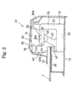
- Fig. 2 is an explanatory cross sectional side view to show the relation between stapler body and base plate thereof which are disposed on the top portion of a post processing apparatus.
- Fig. 3 is an explanatory cross sectional side view to show the stapler body of Fig. 2.
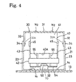
- Fig. 4 is a front view to show a stapler body.
- Fig. 5 is a perspective view to show a table.
- Fig. 6 (A) is a side view to show the positional relation among a pile of sheet, table and photo sensor.
- Fig. 6 (B) is a plan view to show the positional relation among a pile of sheets, table and a photo sensor.
- Fig. 7 is an explanatory side view of stapler body which is turned downside up.
-
- Hereafter an embodiment of the stapler according to the present invention will be explained with reference to the drawings.
- In Fig. 1
reference numeral 10 denotes a post processing apparatus disposed to a body ofcopying machine 11. In thepost processing apparatus 10, an upside downtype stapler 12 is disposed for binding a pile of printed sheet which is discharged from thecopying machine body 11 with the surface of copied side down. On the top surface ofpost processing apparatus 10, another upside downtype stapler 20 is also provided. Astapler body 40 of the stapler 20 (Refer to Fig. 2 to Fig. 4) has quite the same structure to that of the stapler body of stapler 12 (not shown) because the same kind of stapler is employed. - As shown in Fig. 2 to Fig. 4, the
stapler 20 comprises abase plate 21 which is fixed on atop board 13 of thepost processing apparatus 10, abracket 30 which is rotatably attached on thebase plate 21, astapler body 40 which is fixed on thebracket 30 and a cartridge 60 (Refer to Fig. 7) which is removably loaded to thestapler body 40. - The
base plate 21 has abase board portion 22 which is fixed by screws N1 on thetop board 13 ofpost processing apparatus 10, andplates base board portion 22. Theplate 23 is formed to have an U-shaped cross section and having supportpillar board portion 24 andarm board portion 25 which is extending from upper portion of the supportpillar board portion 24 to frontward (leftward in Fig. 2). - The
bracket 30 has aflat board portion 31 which is fixed by screws N2 onbottom wall portion 41A of acase 41 of thestapler body 40, andattachment piece flat board portion 31. Respectivelower portions 32K ofattachment pieces 32 are supported by ashaft 34 at the front end portion ofarm board portion 25 of thebase plate 21, and they are rotatable around theshaft 34. - In the above described structure, the
stapler body 40 is attached to thebase plate 21 in order to turn around theshaft 34, and to be in a posture of downside up. - The
stapler body 40 is arranged to be fixed by L-shaped a stopper (fixing means) 70 which is made of magnet on the position shown in Fig. 2 to Fig. 4. Thestopper 70 is attached to thebase board portion 22 ofbase plate 21, and magnetically attracts thestapler body 40 facing to contact together with a top portion ofsupport board 54, which is explained later and to fix thestapler body 40. When thestapler body 40 is fixed by thestopper 70 on the position shown in Fig. 2 to Fig. 4, a micro switch (detecting means) 39 is arranged to detect the presence and fixing of the stapler body. Themicro switch 39 is disposed at the inside portion ofarm board portion 25 of thebase plate 21, it is arranged to be turned on by aconcave portion 32A of theattachment piece 32 ofbracket 30, by this turning on the presence and fixing ofstapler body 40 is detected. - An
upper cover 35 is attached to thebracket 30, aconcave portion 35A is formed at a back portion of theupper cover 35 and for manual operation fingers are put on at the concave portion. Thereference numeral 36 denotes a support plate on which a pile of sheets T to be bundled is put, thereference numeral 37 denotes a cover which is attached at upward of thesupport plate 36, and is fixed on thesupport plate 36 through a support portion which is not shown. - In the
stapler body 40 there are provided a driving mechanism (not shown) which drives sheet of staples (not shown) stored and piled in acartridge 60 to a driving outportion 40A, a driver (not shown) which forwardly and backwardly reciprocates to drive out the staple from the driving outportion 40A, and a table 42 having a clincher (not shown) which clinches the front end portions of driven out staple. - According to the structure that the
stapler body 40 is attached to thebase plate 21 in downside up position, thecartridge 60 is disposed over the table 42 and the table 42 is disposed under thecartridge 60, then the staple is driven out from upper side to lower side of the table 42. - Table 42 is arranged to be reciprocated upwardly and downwardly by rotational movement of a
link member 43 around ashaft 44. Aroller 45 is disposed in upper portion of thelink member 43, and a cam which is not shown in the figure, is contacting with theroller 46, then thelink member 43 is arranged to rotate around theshaft 44 by the rotational movement of the cam. - An
opening 46 is formed on the upper surface of table 42 as shown in Fig. 5, into which legs of staple are inserted after penetrating the pile of sheets T to be bundled, and the clincher (not shown) is disposed under theopening 46, by which the legs of staple are clinched. Aconcave portion 47 is formed at the back ofopening 46 on the upper surface of table 42 and two throughholes bottom portion 47A of theconcave portion 47, andoptical fibers holes - A
photo sensor 50 is disposed at lower part of the table 42 for detecting if a pile of sheets T is put on the table 42 or not. Thisphoto sensor 50 consists of light emission diode (light emission portion) 51 and light receiving diode (light receiving portion) 52, thelight emission diode 51 is arranged to confront with a lower end of theoptical fiber 49A, and thelight receiving diode 52 is arranged to confront with a lower end of theoptical fiber 49B. Thephoto sensor 50 is attached to asupport board 54 which is formed so as to project forwardly from a front end of thetop board 41B ofcase 41 of thestapler body 40. -
Guide pins guide pins hole optical fibers holes - Hereafter the operation of stapler with above described structure will be given.
- A copied paper which is processed by the
copying machine 11 is discharged to thepost processing apparatus 10 with the copied surface down. In case when all the copied papers are bundled, the pile of sheets is bundled bystapler 12 as usual in the prior art technique and it goes to be discharged at thedischarging tray 14. - In case when all the copied papers are not bundled, the copied paper is discharged at the
discharging tray 14 with the copied surface down. - In case when only desired some of the copied paper among all are to be bundled, the desired some of copied papers are put on the
support plate 36 with their copied surface up and inserted so as to contact with bothguide pins - On the other hand, a
light emission diode 51 of thephoto sensor 50 is lighted and the light beam is projected upward through theoptical fiber 49A in the table 42 from the top end ofoptical fiber 49A. The projected light beam from the top end ofoptical fiber 49A is reflected by outer surface of the pile of sheets T and enters back to theoptical fiber 49B in the table 42. The entered light to theoptical fiber 49B is projected from the bottom end ofoptical fiber 49B and it is received by alight receiving diode 52 of thephoto sensor 50. - When the
light receiving diode 52 receives the light, the micro switch is turned on, and a control circuit which is not shown in the figure, judges that a pilc of sheets T to be bundled is surely put on thesupport plate 36, then it makes an order to start a motor (not shown) driving. The table 42 goes up by this driving of motor in order for pile of sheets T to be put and held between the table 42 and the driving outportion 40A. Then a staple is driven out from the driving outportion 40A and the legs of staple penetrate through the pile of sheets T and the legs of staple are clinched by the clincher arranged on the table 42, thus the pile of sheets is bundled by the stapler. The table 42 goes down and returns to its home position after whole process has been completed. - When the
cartridge 60 is exchanged, thesupport board 54 ofstapler body 40 is detached from thestopper 70 and thestapler body 40 is turned around in counter clockwise with enforcingstapler body 40 and theupper cover 35 to turn counter clockwise by handling operation at theconvex portion 35A ofupper cover 35 as shown in Fig. 7. Thestapler body 40 takes a posture upside down. By this motion thestapler body 40 returns to be normal position. - When the
stapler body 40 is turned around as shown in Fig. 7, it is fixed at the position by a stopper which is not shown in the figure. Then thecartridge 60 is pulled slantwise out to upward andnew cartridge 60 is inserted into thestapler body 40 in order to be loaded. - As described above, the exchange of
cartridge 60 is easily attained by inserting slantwise thecartridge 60 to downward intostapler body 40. - When the
stapler 40 is in a posture of turning around, because themicro switch 39 is turned to off, it is prevented that thestapler body 40 is driven in error. - After the loading of
cartridge 60 is completed, thestapler body 40 is turned again reverse to the above, in clockwise with theupper cover 35 in order to be in the position shown in Fig. 2 to Fig. 4. - As above described even by the upside down positioned
type stapler 20 the pile of sheets T can be bundled with its copied surface up, and the loading ofcartridge 60 can be easily achieved by turning thestapler body 40. Further, because the same upside down positioned type model of stapler is used for both of thestapler body 40 andstapler body 12, reduction of material cost is achieved, and the same type of stapler and the same way to bundle is used because the same type of cartridge is employed, the appearance of pile of sheets bundled bystapler 12 and bystapler 20 seems to be same and it gives a good feeling. - Moreover, because the
photo sensor 50 is attached to thesupport board 54 oftop board 41B of thestapler 40, it is prevented that the lead wire W is extended and loosened together with an upward and downward movement of the table 42. By this structure a cut off problem of the lead wire W with friction does not occur. And there is no need to make lead wire W longer for loosening portion. - Further, because the light is emitted through the
optical fiber 49A in the table 42 to the pile of sheets T, the light which is emitted from thelight emission diode 51 ofphoto sensor 50, can be projected on the surface of pile of sheets T without being weakened. As the structure is arranged to receive the reflected light from pile of sheets T through theoptical fiber 49B in the table 42 by thelight receiving diode 52 ofphoto sensor 50, the reflected light from the pile of sheets T can be received without being weakened. By this fact the detection of pile of sheets T can be surely achieved even when the distance between thephoto sensor 50 and the pile of sheets T is much long. - In the above described embodiment two
optical fiber optical fiber light emission diode 51 is large and at the same time the reflectivity of pile of sheets T for light is high.
Claims (5)
- A stapler comprising,a driving out portion from which a stapler is driven out;a table which forwardly and backwardly reciprocates; anda clincher which is disposed on said table so as to put and hold a pile of sheets to be bundled between itself and said driving out portion when said table forwardly moves and at the same time a stapler is driven out from the driving out portion against the pile of sheets, and to clinch the front end portions of the staple which penetrate through the pile of sheets,said stapler characterized in that,a photo sensor is disposed in the other side of said table opposite to said driving out portion; andone or more through holes are arranged in said table in order to guide the emitted light beam from a light emission portion of said photo sensor to the pile of sheets and to guide the reflected light beam from a surface of the pile of sheets to a light receiving portion of said photo sensor.
- A stapler according to claim 1, characterized in that one or more optical fibers are disposed in said one or more through holes.
- A stapler according to claim 1, characterized in that a concave portion is formed on a surface of support plate of said table on which the pile of sheets to be bundled is put, and said one or more through holes are disposed at a bottom portion of said concave portion.
- A stapler according to claim 3, characterized in that said through holes are consisted by respective two holes for light emission and light receiving.
- A stapler according to claim 4 characterized in that optical fibers are disposed in said two through holes.
Applications Claiming Priority (2)
| Application Number | Priority Date | Filing Date | Title |
|---|---|---|---|
| JP2000084790 | 2000-03-24 | ||
| JP2000084790A JP4296679B2 (en) | 2000-03-24 | 2000-03-24 | Electric stapler |
Publications (2)
| Publication Number | Publication Date |
|---|---|
| EP1136207A1 true EP1136207A1 (en) | 2001-09-26 |
| EP1136207B1 EP1136207B1 (en) | 2004-06-02 |
Family
ID=18601219
Family Applications (1)
| Application Number | Title | Priority Date | Filing Date |
|---|---|---|---|
| EP01250106A Expired - Lifetime EP1136207B1 (en) | 2000-03-24 | 2001-03-23 | Stapler |
Country Status (4)
| Country | Link |
|---|---|
| US (1) | US6484921B2 (en) |
| EP (1) | EP1136207B1 (en) |
| JP (1) | JP4296679B2 (en) |
| DE (1) | DE60103575T2 (en) |
Cited By (1)
| Publication number | Priority date | Publication date | Assignee | Title |
|---|---|---|---|---|
| EP2255935A1 (en) * | 2009-05-28 | 2010-12-01 | Max Co., Ltd. | Electric stapler |
Families Citing this family (11)
| Publication number | Priority date | Publication date | Assignee | Title |
|---|---|---|---|---|
| JP2002066952A (en) * | 2000-09-01 | 2002-03-05 | Nisca Corp | Staple storage unit and stapler device having the same |
| JP2002128381A (en) * | 2000-10-31 | 2002-05-09 | Canon Aptex Inc | Sheet processing apparatus and image forming apparatus having the same |
| SE523684C2 (en) * | 2001-10-04 | 2004-05-11 | Isaberg Rapid Ab | Control device for a drive motor in a stapler |
| ATE542653T1 (en) * | 2001-11-15 | 2012-02-15 | Max Co Ltd | BRACKET MAGAZINE |
| WO2005102610A2 (en) * | 2004-04-20 | 2005-11-03 | Acco Brands Usa Llc | Stapler with paper guide |
| CN100537153C (en) * | 2004-04-20 | 2009-09-09 | 阿科布兰兹美国有限责任公司 | Stapling machine |
| US7311236B2 (en) * | 2005-04-25 | 2007-12-25 | Tsi Manufacturing Llc | Electric stapler having two anvil plates and workpiece sensing controller |
| TWI332445B (en) * | 2008-12-05 | 2010-11-01 | Pegatron Corp | Stapler |
| JP5212259B2 (en) * | 2009-05-28 | 2013-06-19 | マックス株式会社 | Electric stapler |
| JP5724729B2 (en) * | 2011-08-01 | 2015-05-27 | マックス株式会社 | Stapler |
| US10786892B2 (en) * | 2015-11-30 | 2020-09-29 | Uchida Yoko Global Limited | Stapling device |
Citations (4)
| Publication number | Priority date | Publication date | Assignee | Title |
|---|---|---|---|---|
| US2770805A (en) * | 1955-02-25 | 1956-11-20 | Elzer Philip | Stapling machines |
| US4940177A (en) * | 1988-12-30 | 1990-07-10 | Jimena Carlos L | Electric stapler having electronic control circuit |
| EP0779134A1 (en) * | 1995-12-11 | 1997-06-18 | Max Co., Ltd. | Electric stapler |
| WO1999042253A1 (en) * | 1998-02-05 | 1999-08-26 | Josef Kihlberg Ab | Safety arrangement in a fastener driving tool |
Family Cites Families (14)
| Publication number | Priority date | Publication date | Assignee | Title |
|---|---|---|---|---|
| US3055009A (en) * | 1961-07-12 | 1962-09-25 | Earl T March | Jogger stapler |
| US3994427A (en) * | 1975-04-29 | 1976-11-30 | Pitney-Bowes, Inc. | Automatic sheet jogging and stapling machine |
| US4386725A (en) * | 1980-11-03 | 1983-06-07 | Xerox Corporation | Stapler apparatus with means to determine staple supply |
| US4676421A (en) * | 1986-03-31 | 1987-06-30 | Penn Engineering & Manufacturing Corp. | Press having a programmable ram with sensing means |
| JPS63104864A (en) * | 1986-10-22 | 1988-05-10 | Hitachi Ltd | paper detection device |
| JPS6324518A (en) * | 1987-04-21 | 1988-02-01 | マックス株式会社 | Start switch for electrically-operated stapler |
| JP3293878B2 (en) * | 1992-06-01 | 2002-06-17 | キヤノン株式会社 | Recording device |
| JPH05330268A (en) * | 1992-06-03 | 1993-12-14 | Canon Inc | Sheet binding apparatus and image forming apparatus |
| JPH06234260A (en) * | 1993-02-10 | 1994-08-23 | Seiko Epson Corp | Thermal printer |
| JPH07237788A (en) * | 1994-03-02 | 1995-09-12 | Fuji Xerox Co Ltd | Paper detection device for image forming apparatus |
| US5562064A (en) * | 1995-03-08 | 1996-10-08 | Diversified Technologies, Inc. | Apparatus and method for assessing damage and patching openings in hulls of marine vessels |
| JP3094881B2 (en) * | 1995-12-20 | 2000-10-03 | マックス株式会社 | Electric stapler |
| JP3554632B2 (en) * | 1996-05-13 | 2004-08-18 | ニスカ株式会社 | Electric stapler |
| JP3436029B2 (en) * | 1996-12-20 | 2003-08-11 | マックス株式会社 | Staple detection device for electric stapler |
-
2000
- 2000-03-24 JP JP2000084790A patent/JP4296679B2/en not_active Expired - Lifetime
-
2001
- 2001-03-23 EP EP01250106A patent/EP1136207B1/en not_active Expired - Lifetime
- 2001-03-23 DE DE60103575T patent/DE60103575T2/en not_active Expired - Fee Related
- 2001-03-26 US US09/817,553 patent/US6484921B2/en not_active Expired - Lifetime
Patent Citations (4)
| Publication number | Priority date | Publication date | Assignee | Title |
|---|---|---|---|---|
| US2770805A (en) * | 1955-02-25 | 1956-11-20 | Elzer Philip | Stapling machines |
| US4940177A (en) * | 1988-12-30 | 1990-07-10 | Jimena Carlos L | Electric stapler having electronic control circuit |
| EP0779134A1 (en) * | 1995-12-11 | 1997-06-18 | Max Co., Ltd. | Electric stapler |
| WO1999042253A1 (en) * | 1998-02-05 | 1999-08-26 | Josef Kihlberg Ab | Safety arrangement in a fastener driving tool |
Cited By (2)
| Publication number | Priority date | Publication date | Assignee | Title |
|---|---|---|---|---|
| EP2255935A1 (en) * | 2009-05-28 | 2010-12-01 | Max Co., Ltd. | Electric stapler |
| US8365970B2 (en) | 2009-05-28 | 2013-02-05 | Max Co., Ltd. | Electric stapler that detects paper |
Also Published As
| Publication number | Publication date |
|---|---|
| US6484921B2 (en) | 2002-11-26 |
| JP4296679B2 (en) | 2009-07-15 |
| JP2001269904A (en) | 2001-10-02 |
| DE60103575T2 (en) | 2005-06-09 |
| DE60103575D1 (en) | 2004-07-08 |
| EP1136207B1 (en) | 2004-06-02 |
| US20010023887A1 (en) | 2001-09-27 |
Similar Documents
| Publication | Publication Date | Title |
|---|---|---|
| EP1136207B1 (en) | Stapler | |
| US6698640B2 (en) | Motor operated stapler | |
| EP1426155B1 (en) | Staple detection mechanism of electric stapler | |
| EP1136208B1 (en) | Stapler | |
| JP5333083B2 (en) | Electric stapler | |
| US8365970B2 (en) | Electric stapler that detects paper | |
| US7105760B2 (en) | Operation button mounting structure, and image forming apparatus and electronic apparatus equipped with the same | |
| JP3094881B2 (en) | Electric stapler | |
| JP5233843B2 (en) | Electric stapler | |
| GB2260289A (en) | An electrically-powered stapling machine | |
| JP4103700B2 (en) | Staple detection mechanism of electric stapler | |
| EP1649991A1 (en) | Staple leg-bending mechanism | |
| JPH01146674A (en) | sheet binding device | |
| JPH058580A (en) | Sheet binding device | |
| JPH01146672A (en) | Sheet binder | |
| JP3467996B2 (en) | Clip device | |
| JPH0994770A (en) | Standby position detection mechanism for driver plate in electric stapler | |
| JP3489304B2 (en) | Electric stapler | |
| JP4923354B2 (en) | Driver unit and electric stapler | |
| JP3468006B2 (en) | Clip device | |
| JP2004114354A (en) | Sensor device of motor-driven stapler | |
| JPS6274848A (en) | recording device |
Legal Events
| Date | Code | Title | Description |
|---|---|---|---|
| PUAI | Public reference made under article 153(3) epc to a published international application that has entered the european phase |
Free format text: ORIGINAL CODE: 0009012 |
|
| AK | Designated contracting states |
Kind code of ref document: A1 Designated state(s): DE FR GB NL SE Kind code of ref document: A1 Designated state(s): AT BE CH CY DE DK ES FI FR GB GR IE IT LI LU MC NL PT SE TR |
|
| AX | Request for extension of the european patent |
Free format text: AL;LT;LV;MK;RO;SI |
|
| 17P | Request for examination filed |
Effective date: 20011128 |
|
| AKX | Designation fees paid |
Free format text: DE FR GB NL SE |
|
| GRAP | Despatch of communication of intention to grant a patent |
Free format text: ORIGINAL CODE: EPIDOSNIGR1 |
|
| GRAS | Grant fee paid |
Free format text: ORIGINAL CODE: EPIDOSNIGR3 |
|
| GRAA | (expected) grant |
Free format text: ORIGINAL CODE: 0009210 |
|
| AK | Designated contracting states |
Kind code of ref document: B1 Designated state(s): DE FR GB NL SE |
|
| REG | Reference to a national code |
Ref country code: GB Ref legal event code: FG4D |
|
| REF | Corresponds to: |
Ref document number: 60103575 Country of ref document: DE Date of ref document: 20040708 Kind code of ref document: P |
|
| REG | Reference to a national code |
Ref country code: SE Ref legal event code: TRGR |
|
| ET | Fr: translation filed | ||
| PLBE | No opposition filed within time limit |
Free format text: ORIGINAL CODE: 0009261 |
|
| STAA | Information on the status of an ep patent application or granted ep patent |
Free format text: STATUS: NO OPPOSITION FILED WITHIN TIME LIMIT |
|
| 26N | No opposition filed |
Effective date: 20050303 |
|
| PGFP | Annual fee paid to national office [announced via postgrant information from national office to epo] |
Ref country code: NL Payment date: 20070228 Year of fee payment: 7 |
|
| PGFP | Annual fee paid to national office [announced via postgrant information from national office to epo] |
Ref country code: SE Payment date: 20070306 Year of fee payment: 7 |
|
| PGFP | Annual fee paid to national office [announced via postgrant information from national office to epo] |
Ref country code: GB Payment date: 20070329 Year of fee payment: 7 |
|
| PGFP | Annual fee paid to national office [announced via postgrant information from national office to epo] |
Ref country code: DE Payment date: 20070330 Year of fee payment: 7 |
|
| PGFP | Annual fee paid to national office [announced via postgrant information from national office to epo] |
Ref country code: FR Payment date: 20070328 Year of fee payment: 7 |
|
| EUG | Se: european patent has lapsed | ||
| GBPC | Gb: european patent ceased through non-payment of renewal fee |
Effective date: 20080323 |
|
| PG25 | Lapsed in a contracting state [announced via postgrant information from national office to epo] |
Ref country code: NL Free format text: LAPSE BECAUSE OF NON-PAYMENT OF DUE FEES Effective date: 20081001 |
|
| NLV4 | Nl: lapsed or anulled due to non-payment of the annual fee |
Effective date: 20081001 |
|
| REG | Reference to a national code |
Ref country code: FR Ref legal event code: ST Effective date: 20081125 |
|
| PG25 | Lapsed in a contracting state [announced via postgrant information from national office to epo] |
Ref country code: DE Free format text: LAPSE BECAUSE OF NON-PAYMENT OF DUE FEES Effective date: 20081001 Ref country code: SE Free format text: LAPSE BECAUSE OF NON-PAYMENT OF DUE FEES Effective date: 20080324 |
|
| PG25 | Lapsed in a contracting state [announced via postgrant information from national office to epo] |
Ref country code: FR Free format text: LAPSE BECAUSE OF NON-PAYMENT OF DUE FEES Effective date: 20080331 |
|
| PG25 | Lapsed in a contracting state [announced via postgrant information from national office to epo] |
Ref country code: GB Free format text: LAPSE BECAUSE OF NON-PAYMENT OF DUE FEES Effective date: 20080323 |