JP3554632B2 - Electric stapler - Google Patents
Electric stapler Download PDFInfo
- Publication number
- JP3554632B2 JP3554632B2 JP11751596A JP11751596A JP3554632B2 JP 3554632 B2 JP3554632 B2 JP 3554632B2 JP 11751596 A JP11751596 A JP 11751596A JP 11751596 A JP11751596 A JP 11751596A JP 3554632 B2 JP3554632 B2 JP 3554632B2
- Authority
- JP
- Japan
- Prior art keywords
- sheet bundle
- sheet
- guide member
- actuator
- electric stapler
- Prior art date
- Legal status (The legal status is an assumption and is not a legal conclusion. Google has not performed a legal analysis and makes no representation as to the accuracy of the status listed.)
- Expired - Lifetime
Links
Images


Classifications
-
- B—PERFORMING OPERATIONS; TRANSPORTING
- B27—WORKING OR PRESERVING WOOD OR SIMILAR MATERIAL; NAILING OR STAPLING MACHINES IN GENERAL
- B27F—DOVETAILED WORK; TENONS; SLOTTING MACHINES FOR WOOD OR SIMILAR MATERIAL; NAILING OR STAPLING MACHINES
- B27F7/00—Nailing or stapling; Nailed or stapled work
- B27F7/02—Nailing machines
- B27F7/025—Nailing machines for inserting joint-nails
Landscapes
- Engineering & Computer Science (AREA)
- Mechanical Engineering (AREA)
- Life Sciences & Earth Sciences (AREA)
- Forests & Forestry (AREA)
- Portable Nailing Machines And Staplers (AREA)
- Dovetailed Work, And Nailing Machines And Stapling Machines For Wood (AREA)
Description
【0001】
【発明の属する技術分野】
本発明は、シート束(シート状物)をステープルにより綴じるための電動ステープラに関し、特に、シート束に対する平行打ちのみでなく斜め打ちも可能な電動ステープラに関する。
【0002】
【従来の技術】
従来より、シート束挿入用間隙の奥部にステープリング部を備え、上記間隙に対しシート束の端縁が挿入されるのに伴い該シート束の端縁の2箇所に当接し、該シート束に押されて移動することによりスイッチを作動して上記シート束に平行打ちステープリングを施すアクチュエータを備えてなる電動ステープラが知られている。
【0003】
ここで、「平行打ち」とは、シート束の直線状端縁を、この端縁の延長方向と直角方向に移動させる態様でステープラの間隙内に挿入して、ステープルを上記端縁の近傍にこの端縁と平行になるように打ち込むことを意味し、「斜め打ち」とは、シート束の隅部をステープラの間隙内に挿入して、ステープルを上記隅部に、この隅部を挟むシート束の2側縁に対し斜めになるように打ち込むことを意味する。
【0004】
【発明が解決しようとする課題】
ところで、通常の電動ステープラにおいては、上記アクチュエータがシート束の幅方向に所定の間隔を保って上記間隙内に配置された一対の部材を備えていて、これら部材が平行打ちの場合にシート束の端縁に当接して、シート束を所定の平行打ち位置に案内するガイド部材として機能するように構成されているが、このステープラを用いてシート束に斜め打ちを施す場合、シート束の隅部の所定位置がステープラの間隙の奥部のステープリング部に達しても、このシート束の位置では、隅部を挟むシート束の2側縁がアクチュエータに当接することができず、敢えて2側縁がアクチュエータに当接する位置までシート束を間隙内に挿入すると、シート束の隅部の所定位置から遙かに離れた位置に斜め打ちが施されてしまうことになる。
【0005】
もっとも、電動ステープラを作動させるための手動の押しボタンスイッチ等を別個に設け、斜め打ちの場合は、ステープラの間隙内にシート束の隅部を適当に挿入した位置で上記押しボタンスイッチを押すことによって、斜め打ちを行なうことは可能であるが、その場合はシート束上の一定位置にステープリングを施すことは困難である。
【0006】
そのため、従来は、この種の電動ステープラを用いてシート束に斜め打ちを施すために、電動ステープラに斜め打ち専用のアダプタを電動ステープラに取り付けて行なっていたが、平行打ちと併用する場合は、このアダプタをその度に着脱しなければならず、また取り外されたアダプタが紛失したりする等の問題があった。
【0007】
上述の事情に鑑み、本発明は、シート束に対する平行打ちが可能な状態と斜め打ちが可能な状態とを極めて簡単な操作で切り換えることができる電動ステープラを提供することを目的とする。
【0008】
【課題を解決するための手段】
本発明による電動ステープラは、ステープリング部を通過して挿入されるシート状物の端縁の2箇所以上に当接し上記シート状物の挿入に伴って移動することによりスイッチを作動してステープリング動作を起動させるためのアクチュエータを備えた電動ステープラにおいて、
上記アクチュエータよりもシート状物の挿入方向手前に位置しこの挿入されるシート状物に当接しない倒伏状態と当接する起立状態とに切換え可能であって、上記起立状態ではシート状物の隅部が上記ステープリング部を通過して挿入されるとき該隅部を挟む2側縁に当接し、かつシート状物の挿入に伴って移動することにより上記アクチュエータを移動させて上記スイッチを作動するガイド部材を備えてなることを特徴とするものである。
【0009】
その場合、上記斜め打ち用ガイド部材を一方向に付勢するばね部材を設け、上ガイド部材が上記ばね部材の付勢力に抗して移動せしめられることにより上記アクチュエータに当接して該アクチュエータを作動させるように構成することが好ましい。
【0010】
【発明の効果】
本発明によれば、上記ガイド部材を起倒させるだけで、平行打ちが可能な状態と斜め打ちとが可能な状態とに直ちに切り換えることができるから、切り換えが極めて簡単であり、かつ上記ガイド部材に恒久的に電動ステープラ本体に取り付けられているから、従来の専用アダプタを用いる場合のように、紛失の問題が解消される。
【0011】
また、平行打ちの場合も斜め打ちの場合も、共通のアクチュエータがスイッチを作動させるように構成されているから、制御系が簡単になる利点がある。
【0012】
【発明の実施の形態】
以下、電動ステープラの実施の形態を図面に基づいて説明する。
【0013】
図は本発明による電動ステープラの一形態の構成を示すもので、本実施の形態の電動ステープラは、印刷機、複写機等から排出された記録済みシートを順次受容して集積する複数段の分配ビンを備えた「ソータ」と呼ばれるシート分配装置に外付けされるものである。
【0014】
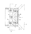
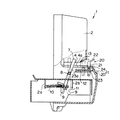
図1は斜め打ち用ガイド部材が起立状態にあるときの正面図、図2は斜め打ち用ガイド部材が起立状態にあるときのシート束挿入用間隙のシート束載置面上の配置を、シート束載置面よりも下方の構造部分は省略して示す平面図、図3は斜め打ち用ガイド部材が倒伏状態にあるときの背面側から透視的に見た斜視図、図4は斜め打ち用ガイド部材が起立状態にあるときの縦断側面図、図5は図4の要部の拡大図である。
【0015】
図において、この電動ステープラ1は、ステープリングを施すべきシート束3(図2)の挿入用間隙4を、本体フレーム2の前面から両側面に亘って開口する態様で備え、この間隙4は、平坦な水平面をシート束載置面4aとして有している。間隙4の奥部にはステープリング部5が設けられ、ステープリング部5の両側のシート束載置面4a上には、シート束挿入方向(図2および図4の右方から左方に向かう方向)に沿って延びる一対の溝6,6が形成され、これら溝6,6からレバー7,7がそれぞれシート束載置面4a上に突出している。
【0016】
各レバー7は、シート束載置面4aの下方において図4の紙面に垂直な方向を軸線方向とする軸8に揺動自在に軸支されているとともに、両レバー7,7の下端部は、図4の紙面に垂直な方向に延びる連結部材9によって互いに連結されている。さらに、連結部材9には、本体フレーム2に垂設された係止片2aに一端が係止されたコイルばね10の他端が係止されていることによって、レバー7,7は、その上端が間隙4の入口に向かう方向、すなわち図4の時計方向に回転するように付勢され、溝6,6の間隙4の入口側の端部に当接した状態で、図4に実線で示す位置に停止している。
【0017】
本体フレーム2内には、この電動ステープラ1を作動させるためのスイッチ11が取付け片2bを介して固設されており、上記レバー7,7の下端部あるいは連結部材9が図4の反時計方向に回動して所定位置に達すると、スイッチ11がONになってステープリングが行なわれるように構成されている。すなわち、レバー7,7はスイッチ11を作動させるためのアクチュエータとして機能する。
【0018】
上記間隙4の入口近傍には、斜め打ち用ガイド部材20が起倒可能に設けられている。シート束載置面4a上には、図2から明らかなように、前記レバー7,7が突出している溝6,6から間隙4の入口側に離れた位置に、シート束挿入方向に沿って延びる一対の溝13,13が所定の間隔を隔てて形成されており、上記ガイド部材20は、図1,図2および図4に示すその起立状態において上記溝13,13内からシート束載置面4a上に突出する一対の脚片21,21と、これら脚片21,21の上端部間を連結する細長い平板状の連結バー22とによって一体に構成され、かつ連結バー22は、図4から明らかなように、間隙4の奥側に向かって低くなるような所定の傾斜角を有する。
【0019】
シート束載置面4aの上記溝13,13の下方には、本体フレーム2に水平状態に設けられたガイド板12に案内されて図4の左右方向に摺動可能な一対の摺動部材23,23が設けられている。そして、摺動部材23,23は、図3に示すように、ビス14によって中央部分を本体フレームに係止された線状のばね25(図4、図5では省略)によって、図4および図5の右方に付勢されている。
【0020】
上記摺動部材23,23の間隙入口側の端部には、上記ガイド部材20の各脚片21の基端が、それぞれ図4および図5の紙面に垂直な方向を軸線方向とする軸24の周りで約90°の角度範囲内で回動可能に取り付けられている。ガイド部材20は、図4および図5に実線で示すように、脚片21,21が直立した起立状態と、図4および図5に仮想線で示すように、脚片21,21が水平になった倒伏状態との各位置において、適当なクリック・ストップ機構によってそれぞれ係止されるようになっている。
【0021】
ガイド部材20は、その脚片21,21が起立状態にあるとき、脚片21,21を支持している摺動部材23,23がばね部材25によって図4の右方に付勢されていることによって、実線で示す位置に停止しており、図2に示すように、シート束3の隅部を挟む2側縁3b,3cが間隙4内に挿入されるのに伴って、脚片21,21がシート束3の隅部を挟む2側縁3b,3cにそれぞれ当接し、シート束3をガイドしつつシート束3に押されてばね部材25の付勢力に抗して摺動部材23,23とともに溝13,13に沿って図4の左方に移動するように構成されている。
【0022】
また、上記ガイド部材20は、作業者が連結バー22を指で押すことによって、軸24の周りで図4の時計方向にほぼ90°回動して仮想線で示す倒伏状態になり、また、この倒伏状態から作業者が連結バー22を指で引き起こしてガイド部材20を図4の反時計方向にほぼ90°回動させることによって起立状態となる。なお、本体フレーム2には、連結バー22を引き起こしを容易にするために、図1に示すように、倒伏状態にあるガイド部材20の連結バー22の下縁に沿って凹部15が形成されている。
【0023】
そして、ガイド部材20が倒伏状態にあるときには、図3および図4に示すように、脚片21,21の上面がシート束載置面4aとほぼ同一高さとなり、かつ連結バー22が上述のように傾斜していることによって、倒伏状態では、連結バー22が間隙4の入口においてシート束載置面4aから下方に傾斜した本体フレーム2の傾斜面2cに密着した姿勢をとり、ガイド部材20が平行打ちのためのシート束3の間隙4への挿入を阻害しないように構成されている。
【0024】
したがって、平行打ちステープリングを行なう場合は、ガイド部材20を倒伏状態にしておいて、図2に示すように、シート束3の直線状端縁3aを、この端縁3aの延長方向と直角方向に移動する態様で間隙4内に挿入すると、この挿入に伴って、レバー7,7がシート束3の端縁3aの2箇所に当接し、端縁3aが斜めにならないようにシート束3をガイドしつつシート束3に押されてコイルばね10の付勢力に抗して図4の反時計方向に回動し、シート束3の端縁3aがステープリング部5よりも前方に進入するのを許容する。そして、レバー7,7の下端部あるいは前記連結部材9が所定位置に達すると、スイッチ11がONになって電動ステープラ1が作動され、シート束3の端縁3a近傍に平行打ちステープリングが施されることになる。
【0025】
一方、斜め打ちステープリングを行なうときには、ガイド部材20を起立状態にする。この状態で、図2に示すようにシート束3の隅部を間隙4内に挿入すると、この隅部を挟む2側縁3b,3cがガイド部材20の脚片21,21にそれぞれ当接するから、脚片21,21がシート束3をガイドしつつシート束3に押されてばね部材25の付勢力に抗して溝13,13内を左方に移動する。したがって、脚片21,21を支持している摺動部材23,23も図4の左方に移動する。脚片21,21が所定位置まで移動すると、摺動部材23,23の端面23a,23aがレバー7,7に当接してレバー7,7を回動させ、レバー7,7の下端部あるいは前記連結部材9が所定位置に達すると、スイッチ11がONになって電動ステープラ1が作動されて、シート束3の隅部の図2に仮想線Sで示す位置に斜め打ちステープリングが施されることになる。
【0026】
以上の説明で、電動ステープラの一実施の形態の構成およびその動作が明らかとなったが、本実施の形態によれば、斜め打ち用ガイド部材20を起倒させるだけで、直ちに平行打ちが可能な状態と斜め打ちが可能な状態とに切り換えることができるから、切り換えが極めて簡単であり、かつガイド部材20は電動ステープラ本体に恒久的に設けられているものであるから、従来の専用アダプタを用いる場合のように、紛失の問題が解消される。
【0027】
また、平行打ちの場合も斜め打ちの場合も、レバー7,7あるいは連結部材9が共通のアクチュエータとしてスイッチ11を作動させるように構成されているから、制御系が簡単になる利点がある。
【0028】
なお、本実施の形態では、レバー7,7の下端部あるいは連結部材9によって、スイッチ11が作動されるように構成されているが、これに代え、レバー7,7の回動位置を検出するセンサを用いて電動ステープラを起動させてもよい。
【図面の簡単な説明】
【図1】本発明による電動ステープラの一実施の形態において斜め打ち用ガイド部材が起立状態にあるときの正面図
【図2】同 斜め打ち用ガイド部材が起立状態にあるときのシート束挿入用間隙のシート束載置面上の配置を、シート束載置面よりも下方の構造部分は省略して示す平面図
【図3】同 斜め打ち用ガイド部材が倒伏状態にあるときの背面側から透視的に見た斜視図
【図4】同 斜め打ち用ガイド部材が起立状態にあるときの縦断側面図
【図5】 図4の要部の拡大図 [0001]
TECHNICAL FIELD OF THE INVENTION
The present invention relates to an electric stapler for binding a sheet bundle (sheet-like material) with staples, and more particularly, to an electric stapler that can perform not only parallel hitting but also oblique hitting on a sheet bundle.
[0002]
[Prior art]
Conventionally, a stapling portion is provided at the back of the sheet bundle insertion gap, and the sheet bundle abuts on two edges of the sheet bundle as the edge of the sheet bundle is inserted into the gap. 2. Description of the Related Art There is known an electric stapler including an actuator for operating a switch by being pushed by a member to perform parallel stapling on the sheet bundle.
[0003]
Here, `` parallel striking '' refers to inserting a linear edge of a sheet bundle into a gap of a stapler in a manner to move the edge in a direction perpendicular to the direction in which the edge extends, and placing the staple near the edge. This means that the sheet is driven so as to be parallel to the edge, and "oblique hit" means that the corner of the sheet bundle is inserted into the gap of the stapler, the staple is inserted into the corner, and the sheet sandwiching the corner is inserted. This means that the bundle is driven obliquely with respect to the two side edges.
[0004]
[Problems to be solved by the invention]
By the way, in a usual electric stapler, the actuator includes a pair of members arranged in the gap at a predetermined interval in the width direction of the sheet bundle. The sheet bundle is configured to function as a guide member that guides the sheet bundle to a predetermined parallel hitting position by contacting the edge, but when the sheet bundle is obliquely beaten using this stapler, a corner of the sheet bundle is used. Even if the predetermined position of the sheet bundle reaches the stapling portion deep in the gap of the stapler, the two side edges of the sheet bundle sandwiching the corner portion cannot contact the actuator at the position of the sheet bundle, When the sheet bundle is inserted into the gap to a position where the sheet bundle comes into contact with the actuator, oblique hitting is performed at a position far away from a predetermined position at a corner of the sheet bundle.
[0005]
However, a manual push button switch for operating the electric stapler is separately provided, and in the case of slanting, the push button switch is pressed at a position where the corner of the sheet bundle is appropriately inserted into the gap of the stapler. , It is possible to perform slanting, but in that case, it is difficult to perform stapling at a fixed position on the sheet bundle.
[0006]
For this reason, conventionally, in order to perform oblique hitting on a sheet bundle using this type of electric stapler, an adapter dedicated to oblique hitting was attached to the electric stapler, and this was performed. This adapter must be attached and detached each time, and the removed adapter may be lost.
[0007]
In view of the circumstances described above, an object of the present invention is to provide an electric stapler that can switch between a state in which a sheet bundle can be hit in parallel and a state in which it can be slanted by a very simple operation.
[0008]
[Means for Solving the Problems]
An electric stapler according to the present invention is capable of stapling by operating a switch by abutting at two or more edges of a sheet-like object inserted through a stapling portion and moving with the insertion of the sheet-like object. In an electric stapler provided with an actuator for activating an operation,
It is possible to switch between a falling state in which the actuator is located in the insertion direction of the sheet-like object and a standing state in which the actuator does not contact the inserted sheet-like object and an upright state in which the actuator is in contact with the sheet-like object. A guide that contacts the two side edges sandwiching the corner when inserted through the stapling portion and moves with the insertion of the sheet-like material, thereby moving the actuator to operate the switch. It is characterized by comprising a member.
[0009]
In this case, a spring member for urging the oblique driving guide member in one direction is provided, and the upper guide member is moved against the urging force of the spring member so that the upper guide member comes into contact with the actuator to operate the actuator. It is preferable to configure so that
[0010]
【The invention's effect】
According to the present invention, it is possible to immediately switch between a state in which parallel hitting is possible and a state in which oblique hitting is possible only by raising and lowering the guide member. Since it is permanently attached to the electric stapler body, the problem of loss as in the case of using a conventional dedicated adapter is eliminated.
[0011]
In addition, since the common actuator is configured to operate the switch in both the parallel hit and the oblique hit, there is an advantage that the control system is simplified.
[0012]
BEST MODE FOR CARRYING OUT THE INVENTION
Hereinafter, an embodiment of an electric stapler will be described with reference to the drawings.
[0013]
FIG. 1 shows a configuration of one embodiment of an electric stapler according to the present invention. The electric stapler according to the present embodiment has a multi-stage distribution for sequentially receiving and stacking recorded sheets discharged from a printing machine, a copying machine, or the like. It is externally attached to a sheet distribution device called a "sorter" having a bin.
[0014]
Figure 1 is a front view of the diagonal beating guide member is in the standing state, Figure 2 is disposed on the sheet stack loading surface of the sheet stack insertion gap when the oblique beating guide member is in the upright position, the seat FIG. 3 is a plan view showing a structure portion below the stack mounting surface by omitting the parts , FIG. 3 is a perspective view seen from the back side when the oblique driving guide member is in a lying state, and FIG. FIG . 5 is an enlarged view of a main part of FIG. 4 when the guide member is in an upright state.
[0015]
In this figure, the electric stapler 1 includes a
[0016]
Each of the
[0017]
In the
[0018]
In the vicinity of the entrance of the
[0019]
Below the
[0020]
At the ends of the sliding
[0021]
When the
[0022]
When the operator presses the connecting
[0023]
Then, when the
[0024]
Therefore, when performing the parallel-stapling stapling, the
[0025]
On the other hand, when performing the oblique stapling, the
[0026]
In the above description, the configuration and operation of the embodiment of the electric stapler have been clarified. According to the embodiment, however, the parallel stapling can be immediately performed only by raising and lowering the oblique hitting
[0027]
Further, in both the parallel hit and the oblique hit, since the
[0028]
In the present embodiment, the
[Brief description of the drawings]
FIG. 1 is a front view of an electric stapler according to an embodiment of the present invention when a guide member for oblique driving is in an upright state; FIG. 2 is a view for inserting a sheet bundle when the guide member for oblique driving is in an upright state; FIG. 3 is a plan view showing the arrangement of the gaps on the sheet bundle mounting surface, omitting a structural portion below the sheet bundle mounting surface; FIG. 3 is a view from the back side when the oblique driving guide member is in a lying state; FIG. 4 is a perspective side view of the oblique view. FIG. 4 is a longitudinal side view of the oblique driving guide member in an upright state.
FIG. 5 is an enlarged view of a main part of FIG . 4;
Claims (2)
前記アクチュエータよりも前記シート状物の挿入方向手前に位置し該挿入されるシート状物に当接しない倒伏状態と当接する起立状態とに切換え可能であって、前記起立状態では前記シート状物の隅部が前記ステープリング部を通過して挿入されるとき該隅部を挟む2側縁に当接し、かつ該シート状物の挿入に伴って移動することにより前記アクチュエータを移動させて前記スイッチを作動するガイド部材を備えてなることを特徴とする電動ステープラ。Actuator for starting a stapling operation by operating a switch by abutting at two or more edges of a sheet-like material inserted through a stapling portion and moving with the insertion of the sheet-like material In the electric stapler provided with
It is possible to switch between an upright state in which the actuator is positioned in front of the actuator in a direction of insertion of the sheet and does not contact the inserted sheet, and an upright state in which the sheet is in contact with the sheet. When the corner is inserted through the stapling section, the corner contacts the two side edges sandwiching the corner, and moves along with the insertion of the sheet-like material, thereby moving the actuator to switch the switch. An electric stapler comprising a guide member that operates.
Priority Applications (4)
| Application Number | Priority Date | Filing Date | Title |
|---|---|---|---|
| JP11751596A JP3554632B2 (en) | 1996-05-13 | 1996-05-13 | Electric stapler |
| DE69716995T DE69716995T2 (en) | 1996-05-13 | 1997-05-12 | Electric stapler |
| EP97107728A EP0807499B1 (en) | 1996-05-13 | 1997-05-12 | Electric stapler |
| US08/855,390 US5803337A (en) | 1996-05-13 | 1997-05-13 | Electric stapler |
Applications Claiming Priority (1)
| Application Number | Priority Date | Filing Date | Title |
|---|---|---|---|
| JP11751596A JP3554632B2 (en) | 1996-05-13 | 1996-05-13 | Electric stapler |
Publications (2)
| Publication Number | Publication Date |
|---|---|
| JPH09300307A JPH09300307A (en) | 1997-11-25 |
| JP3554632B2 true JP3554632B2 (en) | 2004-08-18 |
Family
ID=14713680
Family Applications (1)
| Application Number | Title | Priority Date | Filing Date |
|---|---|---|---|
| JP11751596A Expired - Lifetime JP3554632B2 (en) | 1996-05-13 | 1996-05-13 | Electric stapler |
Country Status (4)
| Country | Link |
|---|---|
| US (1) | US5803337A (en) |
| EP (1) | EP0807499B1 (en) |
| JP (1) | JP3554632B2 (en) |
| DE (1) | DE69716995T2 (en) |
Families Citing this family (15)
| Publication number | Priority date | Publication date | Assignee | Title |
|---|---|---|---|---|
| JP3510746B2 (en) * | 1996-11-14 | 2004-03-29 | 理想科学工業株式会社 | Electric stapler |
| US6341772B1 (en) * | 1997-01-10 | 2002-01-29 | Canon Kabushiki Kaisha | In line rotatable stapling device |
| US6199852B1 (en) * | 1998-09-03 | 2001-03-13 | Xerox Corporation | Device for positioning a sheet stack for stapling |
| US6173949B1 (en) * | 1998-09-03 | 2001-01-16 | Xerox Corporation | Device for positioning a sheet stack for stapling |
| US6135337A (en) * | 1999-01-15 | 2000-10-24 | Hunt Holdings, Inc. | Electric stapler |
| JP4296679B2 (en) * | 2000-03-24 | 2009-07-15 | マックス株式会社 | Electric stapler |
| US6547119B2 (en) * | 2001-04-30 | 2003-04-15 | Chien Kai Huang | Power stapler |
| US7090110B2 (en) * | 2003-07-23 | 2006-08-15 | Acco Brands Usa Llc | Paper locator for a stapler |
| US20050023321A1 (en) * | 2003-07-31 | 2005-02-03 | Eric Tsai | Double trigger electric stapler |
| CN100509299C (en) * | 2004-04-20 | 2009-07-08 | 阿科布兰兹美国有限责任公司 | Stapler with paper guide |
| US20060016848A1 (en) * | 2004-07-26 | 2006-01-26 | Iraj Basti | Apparatus for evenly stapling stacks of paper at a desired angle |
| US7311236B2 (en) * | 2005-04-25 | 2007-12-25 | Tsi Manufacturing Llc | Electric stapler having two anvil plates and workpiece sensing controller |
| SE0500911L (en) * | 2005-04-25 | 2006-02-21 | Isaberg Rapid Ab | Stapler |
| EP1955822B1 (en) * | 2005-11-28 | 2012-06-13 | Max Co., Ltd. | Stapler |
| US20110033218A1 (en) * | 2009-08-04 | 2011-02-10 | Kabushiki Kaisha Toshiba | Stapling apparatus, finishing apparatus, and stapling method |
Family Cites Families (8)
| Publication number | Priority date | Publication date | Assignee | Title |
|---|---|---|---|---|
| US4491260A (en) * | 1980-05-27 | 1985-01-01 | Jimena Carlos L | Electric stapler |
| IT1184850B (en) * | 1985-01-25 | 1987-10-28 | Balma Capoduri & C Spa | DRIVE ELEMENT FOR ELECTROMECHANICAL DEVICES FOR THE AUTOMATION OF TABLE STAPLES WITH METAL STITCHES |
| NL8501337A (en) * | 1985-05-10 | 1986-12-01 | Oce Nederland B V Patents And | COPIER EQUIPPED WITH A SHEET ADAPTER. |
| GB2260289B (en) * | 1991-09-10 | 1994-10-19 | Ofrex Group Holdings Plc | Improvements in or relating to an electrically-powered stapling machine |
| JPH05155510A (en) * | 1991-11-29 | 1993-06-22 | Ricoh Co Ltd | Sheet material distribution and storage device |
| JPH07290373A (en) * | 1994-04-21 | 1995-11-07 | Matsushita Electric Ind Co Ltd | Electric stapler |
| US5427296A (en) * | 1994-10-21 | 1995-06-27 | Chen; Bruce | Power stapler |
| US5595336A (en) * | 1995-11-01 | 1997-01-21 | Xerox Corporation | Safety stapler |
-
1996
- 1996-05-13 JP JP11751596A patent/JP3554632B2/en not_active Expired - Lifetime
-
1997
- 1997-05-12 EP EP97107728A patent/EP0807499B1/en not_active Expired - Lifetime
- 1997-05-12 DE DE69716995T patent/DE69716995T2/en not_active Expired - Fee Related
- 1997-05-13 US US08/855,390 patent/US5803337A/en not_active Expired - Lifetime
Also Published As
| Publication number | Publication date |
|---|---|
| EP0807499A3 (en) | 1998-11-18 |
| JPH09300307A (en) | 1997-11-25 |
| DE69716995D1 (en) | 2002-12-19 |
| DE69716995T2 (en) | 2003-03-20 |
| EP0807499B1 (en) | 2002-11-13 |
| US5803337A (en) | 1998-09-08 |
| EP0807499A2 (en) | 1997-11-19 |
Similar Documents
| Publication | Publication Date | Title |
|---|---|---|
| JP3554632B2 (en) | Electric stapler | |
| JP4857504B2 (en) | Electric stapler staple detection mechanism | |
| JP4152893B2 (en) | Stapler having a bending arm for cutting a leg portion of a staple with a pad | |
| JP3344455B2 (en) | Clinch mechanism in stapler | |
| JP3510746B2 (en) | Electric stapler | |
| CN101400484A (en) | Isaberg rapid ab | |
| AU2004315246A1 (en) | Stapler | |
| US7090110B2 (en) | Paper locator for a stapler | |
| JPH05270716A (en) | Sheet depositing device | |
| JP3236647B2 (en) | Staple device | |
| US4515356A (en) | Spring biased crank arm drive for tray mounted stapler | |
| US5181643A (en) | Sheet-stapling device | |
| JP2024092214A (en) | Stapler | |
| EP0189009B1 (en) | A trigger mechanism for an electromechanical actuator for operating a desk stapler | |
| JPH05147285A (en) | Printer | |
| JP4103700B2 (en) | Staple detection mechanism of electric stapler | |
| JP4650611B2 (en) | Stapler clincher mechanism | |
| JP4513439B2 (en) | Stapler movable clincher drive mechanism | |
| JPH0647662Y2 (en) | stapler | |
| WO2005115698A1 (en) | Clincher device for stapler | |
| JP2908865B2 (en) | Sheet folding machine | |
| JPS6030749Y2 (en) | Paper feed device in copying machine | |
| JPH0768478A (en) | Paper binder used for relatively thick stacks of bound materials | |
| JPH0970768A (en) | Clinch mechanism in stapler | |
| GB2072565A (en) | An improved spring-energised strapling machine |
Legal Events
| Date | Code | Title | Description |
|---|---|---|---|
| A131 | Notification of reasons for refusal |
Free format text: JAPANESE INTERMEDIATE CODE: A131 Effective date: 20040120 |
|
| A521 | Written amendment |
Free format text: JAPANESE INTERMEDIATE CODE: A523 Effective date: 20040319 |
|
| TRDD | Decision of grant or rejection written | ||
| A01 | Written decision to grant a patent or to grant a registration (utility model) |
Free format text: JAPANESE INTERMEDIATE CODE: A01 Effective date: 20040420 |
|
| A61 | First payment of annual fees (during grant procedure) |
Free format text: JAPANESE INTERMEDIATE CODE: A61 Effective date: 20040510 |
|
| R150 | Certificate of patent or registration of utility model |
Free format text: JAPANESE INTERMEDIATE CODE: R150 |
|
| R250 | Receipt of annual fees |
Free format text: JAPANESE INTERMEDIATE CODE: R250 |
|
| FPAY | Renewal fee payment (event date is renewal date of database) |
Free format text: PAYMENT UNTIL: 20080514 Year of fee payment: 4 |
|
| FPAY | Renewal fee payment (event date is renewal date of database) |
Free format text: PAYMENT UNTIL: 20090514 Year of fee payment: 5 |
|
| FPAY | Renewal fee payment (event date is renewal date of database) |
Free format text: PAYMENT UNTIL: 20100514 Year of fee payment: 6 |
|
| FPAY | Renewal fee payment (event date is renewal date of database) |
Free format text: PAYMENT UNTIL: 20100514 Year of fee payment: 6 |
|
| FPAY | Renewal fee payment (event date is renewal date of database) |
Free format text: PAYMENT UNTIL: 20110514 Year of fee payment: 7 |
|
| FPAY | Renewal fee payment (event date is renewal date of database) |
Free format text: PAYMENT UNTIL: 20120514 Year of fee payment: 8 |
|
| S531 | Written request for registration of change of domicile |
Free format text: JAPANESE INTERMEDIATE CODE: R313531 |
|
| FPAY | Renewal fee payment (event date is renewal date of database) |
Free format text: PAYMENT UNTIL: 20120514 Year of fee payment: 8 |
|
| R350 | Written notification of registration of transfer |
Free format text: JAPANESE INTERMEDIATE CODE: R350 |
|
| FPAY | Renewal fee payment (event date is renewal date of database) |
Free format text: PAYMENT UNTIL: 20120514 Year of fee payment: 8 |
|
| FPAY | Renewal fee payment (event date is renewal date of database) |
Free format text: PAYMENT UNTIL: 20130514 Year of fee payment: 9 |
|
| FPAY | Renewal fee payment (event date is renewal date of database) |
Free format text: PAYMENT UNTIL: 20140514 Year of fee payment: 10 |
|
| R250 | Receipt of annual fees |
Free format text: JAPANESE INTERMEDIATE CODE: R250 |
|
| R250 | Receipt of annual fees |
Free format text: JAPANESE INTERMEDIATE CODE: R250 |
|
| EXPY | Cancellation because of completion of term |