EP1135562B1 - Wall protector assemblies - Google Patents
Wall protector assemblies Download PDFInfo
- Publication number
- EP1135562B1 EP1135562B1 EP99962897A EP99962897A EP1135562B1 EP 1135562 B1 EP1135562 B1 EP 1135562B1 EP 99962897 A EP99962897 A EP 99962897A EP 99962897 A EP99962897 A EP 99962897A EP 1135562 B1 EP1135562 B1 EP 1135562B1
- Authority
- EP
- European Patent Office
- Prior art keywords
- retainer
- cover
- wall
- straight
- integral
- Prior art date
- Legal status (The legal status is an assumption and is not a legal conclusion. Google has not performed a legal analysis and makes no representation as to the accuracy of the status listed.)
- Expired - Lifetime
Links
Images



Classifications
-
- E—FIXED CONSTRUCTIONS
- E04—BUILDING
- E04F—FINISHING WORK ON BUILDINGS, e.g. STAIRS, FLOORS
- E04F11/00—Stairways, ramps, or like structures; Balustrades; Handrails
- E04F11/18—Balustrades; Handrails
- E04F11/1802—Handrails mounted on walls, e.g. on the wall side of stairs
- E04F11/1804—Details of anchoring to the wall
-
- E—FIXED CONSTRUCTIONS
- E04—BUILDING
- E04F—FINISHING WORK ON BUILDINGS, e.g. STAIRS, FLOORS
- E04F19/00—Other details of constructional parts for finishing work on buildings
- E04F19/02—Borders; Finishing strips, e.g. beadings; Light coves
- E04F19/026—Borders; Finishing strips, e.g. beadings; Light coves specially adapted for cushioning impacts
-
- E—FIXED CONSTRUCTIONS
- E04—BUILDING
- E04F—FINISHING WORK ON BUILDINGS, e.g. STAIRS, FLOORS
- E04F19/00—Other details of constructional parts for finishing work on buildings
- E04F19/02—Borders; Finishing strips, e.g. beadings; Light coves
- E04F19/026—Borders; Finishing strips, e.g. beadings; Light coves specially adapted for cushioning impacts
- E04F19/028—Borders; Finishing strips, e.g. beadings; Light coves specially adapted for cushioning impacts used at protruding corners
Definitions
- ACROVYN ® Construction Specialties, Inc.
- the ACROVYN ® line currently includes handrails, bumper guards, crash rails, corner guards and feature rails that are mounted on building walls, particularly in building areas where impacts from objects moving about are likely to occur, and protect the walls from impacts.
- ACROVYN ® wall protection products are widely used in, for example, hospitals and nursing homes where equipment carts, food carts, wheelchairs, litters and other moving things are ubiquitous. Handrails in such settings also provide the needed support for infirm persons moving about. Products similar to those of the ACROVYN ® line are available from several sources.
- CSI's ACROVYN ® wall protection products and similar handrails, bumper guards, crash rails, corner guards and feature rails generally consist of either continuous extruded aluminum or rigid plastic retainers or spaced-apart mounting clips, which are suitably attached to the wall, and covers of an impact-resistant polymeric material in extruded profile form, such as polyvinyl chloride blended with a small amount of an acrylic polymer, which are attached to the retainers or clips.
- the retainers or clips support the covers on the wall and, in the case of most continuous retainers, provide strength and rigidity; the covers conceal the retainers or clips, provide a good-looking, durable surface, protect walls from impact, are resistant to marring and breaking, are easy to keep clean, and provide architects and designers with an aesthetically versatile system of wall protection devices that comes in many colors, textures and styles. Should the covers be damaged, they can easily be removed from the retainers or clips and replaced. Color coding of wall protectors can provide guidance for occupants, visitors and patients in medical-care and other settings.
- Handrails, bumper guards, crash rails, corner guards, and feature rails having elongated retainers or clips that support covers of a polymeric material are referred to hereinafter as "wall protectors"; the retainers or clips of wall protectors are referred to as “retainers”; and the covers of polymeric material in thin web-like form mounted on the retainers are referred to as "covers.”
- a length of a horizontal wall protector such as a crash rail or a handrail, that is spaced apart from the wall has an exposed end, such as at a door or other opening or at the end of a wall
- an end return piece is attached to the exposed end of the protector, usually by fastening it to the retainer.
- sections of horizontal wall protectors are mounted on walls forming an outside corner, it is common to use a corner piece to join the ends of the sections.
- the ends of corner guards and sections of crash rails and feature rails that are mounted directly against the wall usually have end caps, which close the ends of the cover, conceal the end of the retainer, and hold the cover in position on the retainer in the longitudinal direction.
- end return pieces, corner pieces, and end caps of all wall protectors are separate from the covers, are usually solid bodies that are in most cases made by injection-molding of a polymeric material, and are externally shaped to provide a generally rounded transition between the cover of the wall protector and either the wall on which it is mounted or another cover member on another wall.
- end return pieces have ends that lie close to the wall surface, finish the ends of rail sections for good appearance, and close up the space between the end of the rail section and the wall so that objects that impact them do not get caught on the end of the section. Generally, they are curved so that they deflect an object that contacts them away from the wall.
- Corner pieces usually have an external profile that matches that of the rail so that the surface of the corner piece is flush with the surfaces of the covers of the sections joined by the corner piece.
- end return pieces and corner pieces include mounting brackets for fastening them to the retainers of the wall protectors, the retainers, in turn, being configured to accept the mounting brackets. End caps are sometimes attached directly to the wall.
- Document US 5, 096, 753 discloses a wall protective assembly having an elongated base member fixed to a wall and an overfitting protective member interlocked on the base member. Two protective assemblies on intersecting walls may be joined by an L-shaped corner connector. An end cap may be fitted on the end of a protective assembly so as to cover the base member.
- One object of the present invention is to provide wall protectors that do not require end return pieces or corner pieces that are separate from the covers. Another object is to reduce the number of components that have to be produced and stocked for a given style of wall protector. It is also an object of the invention to improve the appearance of wall protectors by eliminating visible lines where end return pieces or corner pieces abut covers and also eliminating the color and texture differences resulting from the use of end return pieces or corner pieces that are separate from the covers. Still a further object is to simplify the installation of wall protectors.
- a wall protector assembly that includes a retainer adapted to be attached to a building wall and comprising a cover retainer portion, and a cover of an impact resistant thermoplastic polymeric material attached to the cover retainer portion of the retainer.
- the cover includes at least one substantially straight portion of substantially uniform cross section along its length and has an external face portion overlying the retainer on the opposite side of the retainer from the building wall and a transition portion that is integral with the straight portion and has an end wall that curves smoothly away in the lengthwise direction of the straight portion from the external face portion of the straight portion from a rounded juncture with the external face portion and overlies and conceals the end of the retainer.
- the integral transition portion may be configured as an end return piece that forms a transition between the straight portion and a wall surface or as a corner piece that joins sections of wall protectors mounted on walls that intersect at a corner.
- the wall protector assembly according to the invention is defined in claim 1 or claim 4.
- integral transition portion means a portion of a cover that: (1) functions as an end return piece by making a transition between the straight portion and a wall on which the wall protector is mounted and thus closing a gap that would otherwise be left at the end of the straight portion between the wall and both the cover and the retainer on which the cover is mounted; or (2) functions as a corner piece by making a transition between the straight portion and a section of a wall protector that is mounted on an adjacent, intersecting wall.
- the integral transition portion of a cover member provided in accordance with the present invention has several advantages over end return pieces and corner pieces that are separate from the cover of a wall protector, including:
- Figures 1-10, 15, 16, 18-21 are not according to the invention, but are useful to understand it.
- Figures 11 to 14, 17 and 22-25 show wall protector assemblies according to the invention and/or parts thereof.
- the corner guard shown in Figs. 1 to 5 is the same in most respects as CSI's style SM-20 ACROVYN ® corner guard. As shown in Fig. 15, the corner guard is installed vertically on an outside corner where two wall surfaces W1 and W2 intersect. It may extend the full height of the wall corner from a baseboard BB to the ceiling or along only a portion of the height of the wall corner.
- the corner guard consists of a retainer 20 and a cover 30 that overlies and is held in place by the retainer.
- the retainer 20 is a piece cut to the desired length from an extrusion of aluminum or a rigid polymeric material and has in cross section an L-shaped body portion 22 and a retainer flange portion 24 along each edge of the body portion.
- the flange portions 24 diverge from the body portion and are offset from the wall surfaces.
- the cover 30 is formed in the manner described below from an extruded sheet of an impact-resistant thermoplastic polymeric sheet material, polyvinyl chloride (“PVC") blended with a small amount of an acrylic resin being preferred.
- PVC polyvinyl chloride
- the cover has a straight portion of uniform cross section along its length that consists in cross section of an L-shaped face or web portion 32 and a rounded inturned flange portion 34 along each edge of the web portion. As shown in Fig. 1, the groove along each edge of the cover formed by the respective inturned flange portion 34 receives a retainer flange portion 24 of the retainer 20.
- the cover is installed by inserting one leg of the cover over one flange portion 24 of the retainer, pushing that leg toward the retainer to deform the cover, which allows the other cover flange portion to slide past the other retainer flange portion, and then releasing the cover, whereupon the resiliency of the cover pulls the then free leg portion into place to engage the cover and retainer flanges.
- the two legs of the cover web form an inside angle of a few degrees less than 90 degrees.
- the two legs spread apart, thus biasing the flange portions into engagement with the retainer flanges 24 such that the cover is secured on the retainer.
- the resiliency of the two legs allows the cover to yield and thereby absorb some of the energy of the impact.
- At least the upper end of the cover 30, and optionally both ends, has a transition portion 36 that is integral with the straight portion and forms an end wall that is L-shaped in plan (see Figs. 2 and 3) and diverges from the straight portion at rounded junctures with both the web portion and the flange portions.
- the integral transition portion When in place on the retainer, the integral transition portion overlies and conceals the end of the retainer.
- the edge 38 of the integral transition portion 36 is proximate to the wall corner.
- the integral transition portion 36 of the cover of the corner guard provides a transition between the straight portion and the wall. Inasmuch as it is integral with the straight portion, the cover end portion of the cover presents a smooth and unbroken appearance. The color and surface finish of the integral transition portion match those of the straight portion.
- the separate end caps of the prior art corner guards are eliminated, and installation of the cover is facilitated.
- the cover 30 is produced from an initially flat sheet of the PVC/acrylic material by thermal compression molding.
- the sheet is heated to a temperature slightly above the softening point but below the melting point so that it can be deformed plastically and while heated shaped using suitable compression molding apparatus.
- the integral transition portion 36 (or portions) of the cover has in end plan (as viewed from the end) a width slightly greater than the final width, and each edge is faired at the juncture with the inturned retainer flange portions from being turned in to being approximately perpendicular to the plane of the corresponding leg of the web portion 32.
- the integral transition portion is cut away along the free edge and the faired portions to form the finished edge 38.
- the inturned parts of the flange portions 34 end a short distance from the end wall formed by the integral transition portion (see Fig. 5).
- the cover of a corner guard may be formed in one piece to a standard length, say, four feet, that is suitable for most installations. Where a greater height is needed for a particular installation, standard pieces can be cut in half and each half used with a straight length of cover that has no integral transition portions, the straight length forming a butt joint with an upper section having an integral transition portion or upper and lower sections, each of which has an integral transition portion. It is also possible to make unitary covers of various lengths with integral transition portions at both ends.
- a surface-mounted crash rail which is similar in most respects to C/S's ACROVYN ® style SCR-48 crash rail and is shown in Figs. 6 to 10, includes a retainer composed of spaced-apart clips 60, which are fastened at a suitable spacing to the wall W by suitable fasteners, such as expanding wallboard anchors 62, and a longitudinally continuous support channel 64 that snaps onto the clips 60 and carries a cushion 66.
- Each clip 60 has a flange portion 68 at each end.
- a cover 70 having a straight portion 72 which is of uniform cross section along its length and includes a planar web portion 74 and an L-shaped flange portion 76 along each side of the web portion, is received over the retainer and held in place by engagement of the cover flange portions 76 under the retainer flange portions 68 of the clips 60.
- An integral transition portion 78 at the end of the cover 70 turns smoothly away from the straight portion 72 from rounded junctures with the web portion and the flange portions and forms an end wall of the cover that overlies and conceals the retainer clips 60 and support channel 64.
- the end wall formed by the integral transition portion has an external surface that is generated by moving of a straight line along a smoothly curved path, such as an arcuate path.
- the edge 78a of the integral transition portion is planar and substantially flush with the inturned legs of the flange portions 76, and thus lies proximate to the wall as installed.
- the integral transition portion functions as an end cap for the straight portion.
- the cover of Figs. 6 to 10 may be produced by thermal compression forming from flat sheet material in essentially the same way as the corner guard cover of Fig. 1 to 5.
- the edge 78a and faired portions of the integral transition portion as molded are trimmed to the form shown in the drawings (see Fig. 10).
- the cover of Figs. 6 to 10 snaps onto the retainer by hooking one edge to one set of flanges of the clips and pressing the web portion toward the wall; the curved faces of the flange portions 68 of the clips induce flexure of the cover by a camming action, thus causing the other flange portion of the cover 70 to pass by and snap in behind the other set of flange portions of the clips.
- the covers 30 and 70 of Figs. 1 to 10 may also be produced by thermal compression molding from straight lengths of extruded material that have the cross-sectional profile of the final product.
- the end portions are heated and compression-molded using split male mandrels within the profile and female molds with cavities matching the final shapes of the integral transition portions 36 and 78.
- Figs. 11 to 13 show a CSI style HRB-4C ACROVYN ® handrail, which is modified according to the present invention by providing a cover having a transition portion that is integral with a straight portion and serves as an end return at an end of a length of the handrail, such as at a door opening or the end of a section at an outside wall corner.
- Toggle bolts 140 and brackets 142 strongly support a retainer 120 on a wall W that is strengthened by horizontal channels 144 installed between the studs (not shown).
- a curved upper flange portion 122 of the retainer 120 which is an aluminum extrusion, provides the dual functions of securing an upper handgrip portion 132 of a cover 130 to the retainer and supporting the handgrip portion, by which it is engaged.
- a lower flange portion 124 of the retainer receives a lower, inturned flange portion 134 of the cover.
- An elastomeric bumper member 146 which is received by a slot formed by ribs 126 that project out from the web portion 128 of the retainer, engages the web portion 136 of the cover 130 and allows the web portion of the cover to deflect under an impact.
- the cover 130 has a straight portion 130a that is received by an end portion of the retainer and a transition portion 130b that is integral with the straight portion and diverges along a smooth curve from the straight portion toward the wall.
- the cover 130 has a substantially uniform cross section along its entire extent, i.e., along both the straight portion 130a and the integral transition portion 130b.
- the integral transition portion provides an end return that overlies and visually conceals the end of the retainer and closes the gap that would otherwise exist between the end of a straight portion of the handrail and the wall, thus preventing objects from possibly being caught between the end of the rail section and the wall.
- the curvature of the integral transition portion tends to deflect objects that contact it away from the wall.
- the end 130b' of the integral transition portion 130b is planar and located proximate to the wall.
- the shape of the integral transition portion 130b is maintained, and the integral transition portion is strengthened, by a substantially rigid insert 150, which may be molded from a suitable polymeric material.
- a substantially rigid insert 150 which may be molded from a suitable polymeric material.
- One end 150a of the insert 150 abuts the end of the retainer 120; the other end 150b is flush with the end 130b' of the cover. If the integral transition portion 130b is arcuate along its extent, the insert 150 can be inserted from the end. A small amount of an adhesive will hold it in place. If the integral transition portion is not arcuate, the insert can be made in three pieces, one for the upper portion, one for the lower portion and one for the center.
- a straight portion of an HRB-4C cover can be installed on the retainer by engaging the handgrip portion 132 of the cover with the handgrip flange portion 122 of the retainer. With the cover web portion 136 deformed outwardly away from the retainer web portion 128 and the lower flange portion 134 of the cover engaging the sloping front face of the retainer flange portion 124, the cover is pushed toward the retainer, which causes the cover to be deformed by a camming action of the lower retainer flange portion 124 on the lower cover flange portion 134. The lower cover flange portion 134 cover snaps into place on the lower retainer flange portion 124.
- the double curvature of the integral transition portion 130b of the cover 130 limits deformation of a part of the straight portion 130a immediately adjacent to it. Therefore, it will be necessary to either slide the cover 130 on the retainer from the end or snap it on with the integral transition portion displaced longitudinally away from the end of the retainer and then slide it longitudinally into place.
- the cover 130 may be made by thermal forming from either an initially flat extruded sheet of the PVC/acrylic material or an extruded profile of the PVC/acrylic material.
- the sheet In the case of a sheet, the sheet is heated to a high enough temperature to enable it to be plastically deformed and compression molded.
- An extruded profile is likewise heated and compression molded.
- a relatively long length of an extruded profile requires heating and compression-forming only the end portion that is shaped to form the end return.
- the corner piece cover 230 for a CSI HRB-4C handrail according to the invention which is shown in Fig. 14, is very similar to the end return cover 130 of Figs. 11 to 13. It is used to join handrail sections that extend along walls that intersect at an outside corner.
- a smoothly curved integral transition portion 230b joins two substantially straight portions 230a. Each of the straight portions 230a is received on the end portion of a retainer (see Fig. 11).
- the cover 230 is of substantially uniform cross section along its length.
- An insert 250 strengthens and helps retain the shape of the integral transition portion of the cover.
- the corner piece cover of Fig. 14 is made in the same manner as the end return piece cover of Figs. 11 to 13, which is described above.
- Fig. 16 shows a longitudinally continuous retainer 60' for a crash rail, which is known per se. Adhesive or tape strips A are applied to the retainer flange portions 68'.
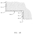
- Crash rails, bumper guards, and feature rails may be installed along portions of walls that meet at inside or outside corners, as shown in Fig. 18.
- one section 60-1 may have a cover 70-1 with an integral transition portion 78-1 that projects beyond the wall corner and overlaps the end of the section 60-2 on the adjoining wall, the end of which adjacent the outside corner has no transition portion.
- the section 60-2 has an integral transition portion 78-2, which is spaced apart from the inside corner.
- the section 60-3 has integral transition portions 78-3 at both ends.
- Figs. 19 to 21 show common installation conditions of crash rails, bumper guards, and feature rails ("protector").
- a protector 60-4 has a cover 70-4 that is unitary along its entire extent and has integral transition portions 78-4 at both ends.
- the protector 60-5 has two covers 70-5a and 70-5b that meet at a butt joint J-5 and have integral transition portions 78-5a and 78-5b.
- the protector 60-6 of Fig. 21 has a center cover 70-6a that meets at butt joints J-6a and J-6b with covers 70-6b and 70-6c, each of which has an integral transition portion 78-6b and 78-6c.
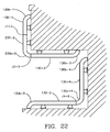
- Figs. 22 to 25 show common installation conditions of handrails.
- one wall adjacent an outside corner receives a handrail section that is composed of a cover 130-1 having an integral transition portion 130b-1 (an end return) at the end remote from the corner and a cover 230-2 that meets the cover 130-1 at a butt joint J1-2 and has an integral transition portion 230b-2 (an outside corner) at the corner end that projects beyond the wall corner and meet the end of a cover section 130-3 on the adjoining wall at a butt joint J2-3.
- the section 130-3 has an integral transition portion 130b-3 (an end return).
- the cover 130-4 has an integral transition portion 130b-4 (an end return) adjacent an inside corner and an inside corner integral transition portion 130c-4 that forms a butt joint J4-5 with a cover 130-5.
- the end of the cover 130-5 remote from the inside corner has an integral transition portion 130b-5.
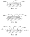
- a handrail section has a cover 130-6 that is unitary along its entire extent and has integral transition portions 130b-6 at both ends.
- the handrail section has two covers 130-7 and 130-8 that meet at a butt joint J7-8 and have integral transition portions 130b-7 and 130b-8 at their ends remote from the joint.
- the handrail of Fig. 25 has a center cover 130-9 that meets at butt joints J9 and J10 with covers 130-10 and 130-11, each of which has an integral transition portion 130b-10 and 130b-11.
- the lengths of the covers may vary considerably, depending on the concepts of the tooling and stocking. It is possible, for example, to provide relatively short cover modules with integral transition portions and use them with cover sections cut to length from straight profiles, which is the concept of Figs. 21 and 25. It is also possible to form unitary covers to custom lengths on a job-by-job basis, which is the concept of Figs. 19 and 23. And the covers can be formed with an integral transition portion at one end, cut to length at the other end, and spliced at a butt joint to make a section, as shown in Fig. 20 and 24. The concepts described above can also be used in combination.
Landscapes
- Engineering & Computer Science (AREA)
- Architecture (AREA)
- Civil Engineering (AREA)
- Structural Engineering (AREA)
- Building Environments (AREA)
- Steps, Ramps, And Handrails (AREA)
- Buffer Packaging (AREA)
- Vibration Dampers (AREA)
Description
- For about twenty-five years, Construction Specialties, Inc. ("CSI"), has marketed a line of wall protection products under the trademark ACROVYN®. The ACROVYN® line currently includes handrails, bumper guards, crash rails, corner guards and feature rails that are mounted on building walls, particularly in building areas where impacts from objects moving about are likely to occur, and protect the walls from impacts. ACROVYN® wall protection products are widely used in, for example, hospitals and nursing homes where equipment carts, food carts, wheelchairs, litters and other moving things are ubiquitous. Handrails in such settings also provide the needed support for infirm persons moving about. Products similar to those of the ACROVYN® line are available from several sources.
- CSI's ACROVYN® wall protection products and similar handrails, bumper guards, crash rails, corner guards and feature rails generally consist of either continuous extruded aluminum or rigid plastic retainers or spaced-apart mounting clips, which are suitably attached to the wall, and covers of an impact-resistant polymeric material in extruded profile form, such as polyvinyl chloride blended with a small amount of an acrylic polymer, which are attached to the retainers or clips. The retainers or clips support the covers on the wall and, in the case of most continuous retainers, provide strength and rigidity; the covers conceal the retainers or clips, provide a good-looking, durable surface, protect walls from impact, are resistant to marring and breaking, are easy to keep clean, and provide architects and designers with an aesthetically versatile system of wall protection devices that comes in many colors, textures and styles. Should the covers be damaged, they can easily be removed from the retainers or clips and replaced. Color coding of wall protectors can provide guidance for occupants, visitors and patients in medical-care and other settings. Handrails, bumper guards, crash rails, corner guards, and feature rails having elongated retainers or clips that support covers of a polymeric material are referred to hereinafter as "wall protectors"; the retainers or clips of wall protectors are referred to as "retainers"; and the covers of polymeric material in thin web-like form mounted on the retainers are referred to as "covers."
- Universally, wherever a length of a horizontal wall protector, such as a crash rail or a handrail, that is spaced apart from the wall has an exposed end, such as at a door or other opening or at the end of a wall, an end return piece is attached to the exposed end of the protector, usually by fastening it to the retainer. Where sections of horizontal wall protectors are mounted on walls forming an outside corner, it is common to use a corner piece to join the ends of the sections. The ends of corner guards and sections of crash rails and feature rails that are mounted directly against the wall usually have end caps, which close the ends of the cover, conceal the end of the retainer, and hold the cover in position on the retainer in the longitudinal direction.
- The end return pieces, corner pieces, and end caps of all wall protectors are separate from the covers, are usually solid bodies that are in most cases made by injection-molding of a polymeric material, and are externally shaped to provide a generally rounded transition between the cover of the wall protector and either the wall on which it is mounted or another cover member on another wall. In particular, end return pieces have ends that lie close to the wall surface, finish the ends of rail sections for good appearance, and close up the space between the end of the rail section and the wall so that objects that impact them do not get caught on the end of the section. Generally, they are curved so that they deflect an object that contacts them away from the wall. Corner pieces usually have an external profile that matches that of the rail so that the surface of the corner piece is flush with the surfaces of the covers of the sections joined by the corner piece. In most cases, end return pieces and corner pieces include mounting brackets for fastening them to the retainers of the wall protectors, the retainers, in turn, being configured to accept the mounting brackets. End caps are sometimes attached directly to the wall.
- Document
US 5, 096, 753 discloses a wall protective assembly having an elongated base member fixed to a wall and an overfitting protective member interlocked on the base member. Two protective assemblies on intersecting walls may be joined by an L-shaped corner connector. An end cap may be fitted on the end of a protective assembly so as to cover the base member. - The use of separate end return pieces, corner pieces and end caps in wall protectors means that there is always a visible line at the intersection of the cover with the end return piece, corner piece, or end cap. It is also difficult to provide a good match between the colors and textures of the end return pieces, cover pieces or end caps and the covers, inasmuch as the methods of making the covers differ from the methods of making the end return pieces, cover pieces and end caps. The visible lines and the differences in color and texture detract from the appearance of the wall protector. The requirement for having separate end return pieces, corner pieces, and end caps involves the costs of manufacturing them, the very high costs of maintaining an inventory, and the costs of installing them, all of which, of course, contribute to the total cost of a wall protector system in a building.
- One object of the present invention is to provide wall protectors that do not require end return pieces or corner pieces that are separate from the covers. Another object is to reduce the number of components that have to be produced and stocked for a given style of wall protector. It is also an object of the invention to improve the appearance of wall protectors by eliminating visible lines where end return pieces or corner pieces abut covers and also eliminating the color and texture differences resulting from the use of end return pieces or corner pieces that are separate from the covers. Still a further object is to simplify the installation of wall protectors.
- The foregoing objects are attained, in accordance with the present invention, by a wall protector assembly that includes a retainer adapted to be attached to a building wall and comprising a cover retainer portion, and a cover of an impact resistant thermoplastic polymeric material attached to the cover retainer portion of the retainer. The cover includes at least one substantially straight portion of substantially uniform cross section along its length and has an external face portion overlying the retainer on the opposite side of the retainer from the building wall and a transition portion that is integral with the straight portion and has an end wall that curves smoothly away in the lengthwise direction of the straight portion from the external face portion of the straight portion from a rounded juncture with the external face portion and overlies and conceals the end of the retainer. The integral transition portion may be configured as an end return piece that forms a transition between the straight portion and a wall surface or as a corner piece that joins sections of wall protectors mounted on walls that intersect at a corner.
- More precisely, the wall protector assembly according to the invention is defined in
claim 1 orclaim 4. - As used herein, in particular, the term "integral transition portion" means a portion of a cover that: (1) functions as an end return piece by making a transition between the straight portion and a wall on which the wall protector is mounted and thus closing a gap that would otherwise be left at the end of the straight portion between the wall and both the cover and the retainer on which the cover is mounted; or (2) functions as a corner piece by making a transition between the straight portion and a section of a wall protector that is mounted on an adjacent, intersecting wall.
- The integral transition portion of a cover member provided in accordance with the present invention has several advantages over end return pieces and corner pieces that are separate from the cover of a wall protector, including:
- (1) elimination of the visible line where the cover meets the separate end return piece or corner piece, thus improving the appearance of the wall protector;
- (2) ensuring uniformity of color and texture of the straight portion and the transition portion;
- (3) eliminating the need to produce and maintain an inventory of, as well as to allocate, pack, and ship to job sites, separate end caps, end return pieces, and corner pieces;
- (4) facilitating installation of the wall protectors.
- For a better understanding of the invention, reference may be made to the following description of exemplary embodiments, taken in conjunction with the accompanying drawings.
-
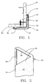
- Fig. 1 is a top cross-sectional view of a corner guard;
- Fig. 2 is a pictorial view of the end portion of the cover of the corner guard of Fig. 1, viewed from above and to one side;
- Fig. 3 is a transverse cross-sectional view of the cover of Fig. 2, taken along the lines 3-3 of Fig. 4 and in the direction of the arrows;
- Fig. 4 is a side cross-sectional view of the cover of Fig. 2, taken along the lines 4-4 of Fig. 3 and in the direction of the arrows;
- Fig. 5 is a fragmentary rear elevational view of a corner portion of one leg of the cover of Fig. 2, viewing the side that faces the wall;
- Fig. 6 is an end cross-sectional view of a crash rail;
- Fig. 7 is a pictorial view of the end portion of the cover of the crash rail of Fig. 6, viewed from in front and to one side;
- Fig. 8 is a transverse cross-sectional view of the cover of Fig. 6, taken along the lines 8-8 of Fig. 9 and in the direction of the arrows;
- Fig. 9 is a side cross-sectional view of the cover of Fig. 6, taken along the lines 9-9 of Fig. 8 and in the direction of the arrows;
- Fig. 10 is a fragmentary rear elevational view of the end portion of the cover of Fig. 6, viewing the side that faces the wall;
- Fig. 11 is an end cross-sectional view of a handrail;
- Fig. 12 is a pictorial view of the end portion of the cover of the handrail of Fig. 11, looking toward the side that faces away from the wall;
- Fig. 13 is a pictorial view of the end portion of the handrail cover of Fig. 12, looking toward the side that faces toward the wall;
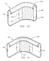
- Fig. 14 is a pictorial view of a corner piece for a handrail of the configuration shown in Fig. 11, viewing the side that faces toward the wall;
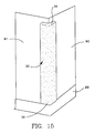
- Fig. 15 is a pictorial view, showing a corner guard installed on a wall corner;
- Fig. 16 is a pictorial view of a portion of a crash rail retainer;
- Fig. 17 is a pictorial view of a portion of a handrail retainer;
- Fig. 18 is a schematic top plan view, illustrating typical installations of crash rails, bumper guards, and feature rails on walls;
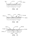
- Figs. 19 to 21 are schematic top plan views of different configurations of crash rails, bumper guards, and feature rails installed on walls;
- Fig. 22 is a schematic top plan view, illustrating typical installations of handrails on walls; and
- Figs. 23 to 25 are schematic top plan views of various configurations of handrails installed on walls.
- The embodiments of Figures 1-10, 15, 16, 18-21 are not according to the invention, but are useful to understand it. Figures 11 to 14, 17 and 22-25 show wall protector assemblies according to the invention and/or parts thereof.
- The corner guard shown in Figs. 1 to 5 is the same in most respects as CSI's style SM-20 ACROVYN® corner guard. As shown in Fig. 15, the corner guard is installed vertically on an outside corner where two wall surfaces W1 and W2 intersect. It may extend the full height of the wall corner from a baseboard BB to the ceiling or along only a portion of the height of the wall corner. The corner guard consists of a
retainer 20 and acover 30 that overlies and is held in place by the retainer. Theretainer 20 is a piece cut to the desired length from an extrusion of aluminum or a rigid polymeric material and has in cross section an L-shapedbody portion 22 and aretainer flange portion 24 along each edge of the body portion. Theflange portions 24 diverge from the body portion and are offset from the wall surfaces. Thecover 30 is formed in the manner described below from an extruded sheet of an impact-resistant thermoplastic polymeric sheet material, polyvinyl chloride ("PVC") blended with a small amount of an acrylic resin being preferred. The cover has a straight portion of uniform cross section along its length that consists in cross section of an L-shaped face orweb portion 32 and a roundedinturned flange portion 34 along each edge of the web portion. As shown in Fig. 1, the groove along each edge of the cover formed by the respectiveinturned flange portion 34 receives aretainer flange portion 24 of theretainer 20. The cover is installed by inserting one leg of the cover over oneflange portion 24 of the retainer, pushing that leg toward the retainer to deform the cover, which allows the other cover flange portion to slide past the other retainer flange portion, and then releasing the cover, whereupon the resiliency of the cover pulls the then free leg portion into place to engage the cover and retainer flanges. As initially formed, the two legs of the cover web form an inside angle of a few degrees less than 90 degrees. When the cover is in place on the retainer, the two legs spread apart, thus biasing the flange portions into engagement with theretainer flanges 24 such that the cover is secured on the retainer. Upon an impact to the cover, the resiliency of the two legs allows the cover to yield and thereby absorb some of the energy of the impact. - At least the upper end of the
cover 30, and optionally both ends, has atransition portion 36 that is integral with the straight portion and forms an end wall that is L-shaped in plan (see Figs. 2 and 3) and diverges from the straight portion at rounded junctures with both the web portion and the flange portions. When in place on the retainer, the integral transition portion overlies and conceals the end of the retainer. Theedge 38 of theintegral transition portion 36 is proximate to the wall corner. Theintegral transition portion 36 of the cover of the corner guard provides a transition between the straight portion and the wall. Inasmuch as it is integral with the straight portion, the cover end portion of the cover presents a smooth and unbroken appearance. The color and surface finish of the integral transition portion match those of the straight portion. The separate end caps of the prior art corner guards are eliminated, and installation of the cover is facilitated. - The
cover 30 is produced from an initially flat sheet of the PVC/acrylic material by thermal compression molding. The sheet is heated to a temperature slightly above the softening point but below the melting point so that it can be deformed plastically and while heated shaped using suitable compression molding apparatus. - As initially formed, the integral transition portion 36 (or portions) of the cover has in end plan (as viewed from the end) a width slightly greater than the final width, and each edge is faired at the juncture with the inturned retainer flange portions from being turned in to being approximately perpendicular to the plane of the corresponding leg of the
web portion 32. The integral transition portion is cut away along the free edge and the faired portions to form thefinished edge 38. The inturned parts of theflange portions 34 end a short distance from the end wall formed by the integral transition portion (see Fig. 5). - The cover of a corner guard may be formed in one piece to a standard length, say, four feet, that is suitable for most installations. Where a greater height is needed for a particular installation, standard pieces can be cut in half and each half used with a straight length of cover that has no integral transition portions, the straight length forming a butt joint with an upper section having an integral transition portion or upper and lower sections, each of which has an integral transition portion. It is also possible to make unitary covers of various lengths with integral transition portions at both ends.
- A surface-mounted crash rail, which is similar in most respects to C/S's ACROVYN® style SCR-48 crash rail and is shown in Figs. 6 to 10, includes a retainer composed of spaced-apart clips 60, which are fastened at a suitable spacing to the wall W by suitable fasteners, such as expanding wallboard anchors 62, and a longitudinally
continuous support channel 64 that snaps onto theclips 60 and carries acushion 66. Eachclip 60 has aflange portion 68 at each end. Acover 70 having astraight portion 72, which is of uniform cross section along its length and includes aplanar web portion 74 and an L-shapedflange portion 76 along each side of the web portion, is received over the retainer and held in place by engagement of thecover flange portions 76 under theretainer flange portions 68 of theclips 60. Anintegral transition portion 78 at the end of thecover 70 turns smoothly away from thestraight portion 72 from rounded junctures with the web portion and the flange portions and forms an end wall of the cover that overlies and conceals the retainer clips 60 andsupport channel 64. The end wall formed by the integral transition portion has an external surface that is generated by moving of a straight line along a smoothly curved path, such as an arcuate path. Theedge 78a of the integral transition portion is planar and substantially flush with the inturned legs of theflange portions 76, and thus lies proximate to the wall as installed. The integral transition portion functions as an end cap for the straight portion. - The cover of Figs. 6 to 10 may be produced by thermal compression forming from flat sheet material in essentially the same way as the corner guard cover of Fig. 1 to 5. The
edge 78a and faired portions of the integral transition portion as molded are trimmed to the form shown in the drawings (see Fig. 10). The cover of Figs. 6 to 10 snaps onto the retainer by hooking one edge to one set of flanges of the clips and pressing the web portion toward the wall; the curved faces of theflange portions 68 of the clips induce flexure of the cover by a camming action, thus causing the other flange portion of thecover 70 to pass by and snap in behind the other set of flange portions of the clips. - The
covers integral transition portions - Figs. 11 to 13 show a CSI style HRB-4C ACROVYN® handrail, which is modified according to the present invention by providing a cover having a transition portion that is integral with a straight portion and serves as an end return at an end of a length of the handrail, such as at a door opening or the end of a section at an outside wall corner.
Toggle bolts 140 andbrackets 142 strongly support aretainer 120 on a wall W that is strengthened byhorizontal channels 144 installed between the studs (not shown). A curvedupper flange portion 122 of theretainer 120, which is an aluminum extrusion, provides the dual functions of securing anupper handgrip portion 132 of acover 130 to the retainer and supporting the handgrip portion, by which it is engaged. Alower flange portion 124 of the retainer receives a lower,inturned flange portion 134 of the cover. Anelastomeric bumper member 146, which is received by a slot formed byribs 126 that project out from theweb portion 128 of the retainer, engages theweb portion 136 of thecover 130 and allows the web portion of the cover to deflect under an impact. - The
cover 130 has astraight portion 130a that is received by an end portion of the retainer and atransition portion 130b that is integral with the straight portion and diverges along a smooth curve from the straight portion toward the wall. Thecover 130 has a substantially uniform cross section along its entire extent, i.e., along both thestraight portion 130a and theintegral transition portion 130b. The integral transition portion provides an end return that overlies and visually conceals the end of the retainer and closes the gap that would otherwise exist between the end of a straight portion of the handrail and the wall, thus preventing objects from possibly being caught between the end of the rail section and the wall. The curvature of the integral transition portion tends to deflect objects that contact it away from the wall. Theend 130b' of theintegral transition portion 130b is planar and located proximate to the wall. - The shape of the
integral transition portion 130b is maintained, and the integral transition portion is strengthened, by a substantiallyrigid insert 150, which may be molded from a suitable polymeric material. One end 150a of theinsert 150 abuts the end of theretainer 120; theother end 150b is flush with theend 130b' of the cover. If theintegral transition portion 130b is arcuate along its extent, theinsert 150 can be inserted from the end. A small amount of an adhesive will hold it in place. If the integral transition portion is not arcuate, the insert can be made in three pieces, one for the upper portion, one for the lower portion and one for the center. - A straight portion of an HRB-4C cover can be installed on the retainer by engaging the
handgrip portion 132 of the cover with thehandgrip flange portion 122 of the retainer. With thecover web portion 136 deformed outwardly away from theretainer web portion 128 and thelower flange portion 134 of the cover engaging the sloping front face of theretainer flange portion 124, the cover is pushed toward the retainer, which causes the cover to be deformed by a camming action of the lowerretainer flange portion 124 on the lowercover flange portion 134. The lowercover flange portion 134 cover snaps into place on the lowerretainer flange portion 124. - The double curvature of the
integral transition portion 130b of thecover 130 limits deformation of a part of thestraight portion 130a immediately adjacent to it. Therefore, it will be necessary to either slide thecover 130 on the retainer from the end or snap it on with the integral transition portion displaced longitudinally away from the end of the retainer and then slide it longitudinally into place. - The
cover 130 may be made by thermal forming from either an initially flat extruded sheet of the PVC/acrylic material or an extruded profile of the PVC/acrylic material. In the case of a sheet, the sheet is heated to a high enough temperature to enable it to be plastically deformed and compression molded. An extruded profile is likewise heated and compression molded. A relatively long length of an extruded profile requires heating and compression-forming only the end portion that is shaped to form the end return. - The
corner piece cover 230 for a CSI HRB-4C handrail according to the invention, which is shown in Fig. 14, is very similar to theend return cover 130 of Figs. 11 to 13. It is used to join handrail sections that extend along walls that intersect at an outside corner. A smoothly curvedintegral transition portion 230b joins two substantiallystraight portions 230a. Each of thestraight portions 230a is received on the end portion of a retainer (see Fig. 11). Thecover 230 is of substantially uniform cross section along its length. Aninsert 250 strengthens and helps retain the shape of the integral transition portion of the cover. The corner piece cover of Fig. 14 is made in the same manner as the end return piece cover of Figs. 11 to 13, which is described above. - In installations of the previously known protective devices that use separate end caps, end return pieces or corner pieces, straight lengths of covers are held against moving axially along the retainers by shoulders on the end caps, end return pieces or corner pieces. Inasmuch as the integral transition portions of covers according to the present invention lack such shoulders, it is desirable to secure the covers to the retainers by applying areas of adhesive or pieces of double-faced adhesive tape A to the retainer flange portions, as is shown in Figs. 16 and 17. The adhesive or tape strips A bond the covers to the retainer. The bond areas can be kept small and can be located near the ends of cover sections to facilitate breaking the bonds for removal of the covers, should it be necessary or desired to replace the covers. Fig. 16 shows a longitudinally continuous retainer 60' for a crash rail, which is known per se. Adhesive or tape strips A are applied to the retainer flange portions 68'.
- Crash rails, bumper guards, and feature rails, all of which are installed with little or no spacing between the flanges of the covers and the wall, may be installed along portions of walls that meet at inside or outside corners, as shown in Fig. 18. At an outside corner one section 60-1 may have a cover 70-1 with an integral transition portion 78-1 that projects beyond the wall corner and overlaps the end of the section 60-2 on the adjoining wall, the end of which adjacent the outside corner has no transition portion. At an inside corner, the section 60-2 has an integral transition portion 78-2, which is spaced apart from the inside corner. The section 60-3 has integral transition portions 78-3 at both ends.
- Figs. 19 to 21 show common installation conditions of crash rails, bumper guards, and feature rails ("protector"). In Fig. 19, a protector 60-4 has a cover 70-4 that is unitary along its entire extent and has integral transition portions 78-4 at both ends. In Fig. 20, the protector 60-5 has two covers 70-5a and 70-5b that meet at a butt joint J-5 and have integral transition portions 78-5a and 78-5b. The protector 60-6 of Fig. 21 has a center cover 70-6a that meets at butt joints J-6a and J-6b with covers 70-6b and 70-6c, each of which has an integral transition portion 78-6b and 78-6c.
- Figs. 22 to 25 show common installation conditions of handrails. As shown to the upper left in Fig. 22, one wall adjacent an outside corner receives a handrail section that is composed of a cover 130-1 having an
integral transition portion 130b-1 (an end return) at the end remote from the corner and a cover 230-2 that meets the cover 130-1 at a butt joint J1-2 and has anintegral transition portion 230b-2 (an outside corner) at the corner end that projects beyond the wall corner and meet the end of a cover section 130-3 on the adjoining wall at a butt joint J2-3. At an inside corner, the section 130-3 has anintegral transition portion 130b-3 (an end return). The cover 130-4 has anintegral transition portion 130b-4 (an end return) adjacent an inside corner and an inside cornerintegral transition portion 130c-4 that forms a butt joint J4-5 with a cover 130-5. The end of the cover 130-5 remote from the inside corner has anintegral transition portion 130b-5. - In Fig. 23, a handrail section has a cover 130-6 that is unitary along its entire extent and has
integral transition portions 130b-6 at both ends. In Fig. 24, the handrail section has two covers 130-7 and 130-8 that meet at a butt joint J7-8 and haveintegral transition portions 130b-7 and 130b-8 at their ends remote from the joint. The handrail of Fig. 25 has a center cover 130-9 that meets at butt joints J9 and J10 with covers 130-10 and 130-11, each of which has anintegral transition portion 130b-10 and 130b-11. - In the various installations shown in Figs. 18 to 25, the lengths of the covers may vary considerably, depending on the concepts of the tooling and stocking. It is possible, for example, to provide relatively short cover modules with integral transition portions and use them with cover sections cut to length from straight profiles, which is the concept of Figs. 21 and 25. It is also possible to form unitary covers to custom lengths on a job-by-job basis, which is the concept of Figs. 19 and 23. And the covers can be formed with an integral transition portion at one end, cut to length at the other end, and spliced at a butt joint to make a section, as shown in Fig. 20 and 24. The concepts described above can also be used in combination.
Claims (6)
- A wall protector assembly having a retainer (120) adapted to be attached to a building wall and comprising a cover retainer portion (128), and a cover (130) of an impact resistant thermoplastic polymeric material attached to the cover retainer portion of the retainer, the cover including at least one substantially straight portion (130a) of substantially uniform transverse cross section along its length and having an external face portion overlying the retainer on the opposite side of the retainer from the building wall, characterized in that the cover has a transition portion (130b) that is integral with the straight portion and has an end wall that curves smoothly away in the lengthwise direction of the straight portion from the external face portion of the straight portion from a rounded juncture with the external face portion and overlies and conceals the lengthwise end of the retainer, the retainer (120) of the assembly being adapted to be mounted on a wall in spaced apart relation, in that the integral transition portion (130b) is configured as an end return piece and makes a transition between the straight portion (130a) and the wall, thus closing a gap that would otherwise be left at the end of the straight portion between the wall and both the cover and the retainer on which the cover is mounted, and in that the shape of the integral transition portion is maintained and the integral transition portion is strengthened by a substantially rigid insert (150).
- The wall protector assembly according to claim 1, characterized in that the insert (150) is molded from a suitable polymeric material.
- The wall protector assembly according to claim 1, characterized in that one end of the insert (150) abuts the end of the retainer and the other end is substantially flush with the end of the cover.
- A wall protector assembly having a retainer adapted to be attached to a building wall and comprising a cover retainer portion (128), and a cover (230) of an impact resistant thermoplastic polymeric material attached to the cover retainer portion of the retainer, the cover including at least one substantially straight portion (230a) of substantially uniform transverse cross section along its length and having an external face portion overlying the retainer on the opposite side of the retainer from the building wall, characterized in that the cover has a transition portion (230b) that is integral with the straight portion and has an end wall that curves smoothly away in the lengthwise direction of the straight portion from the external face portion of the straight portion from a rounded juncture with the external face portion and overlies and conceals the lengthwise end of the retainer, the assembly having first and second sections mounted on intersecting walls, and the integral transition portion (230b) of the cover (230) having two substantially straight portions of the same cross section, one of the straight portions (230a) being received on a retainer mounted on one of the walls and the other straight portion being received on a retainer mounted on the other wall, in that the integral transition portion is intermediate and connects the straight portions, has a cross-sectional shape substantially the same as that of the straight portions and is smoothly curved along its extent, and in that the shape of the integral transition portion is maintained and the integral transition portion is strengthened by a substantially rigid insert (250).
- The wall protector assembly according to claim 4, and further characterized in that the insert (250) is molded from a suitable polymeric material.
- The wall protector assembly according to claim 4 or 5, and further characterized in that one end of the insert (250) abuts the end of the retainer on one wall and the other end abuts the retainer on the other wall.
Applications Claiming Priority (3)
| Application Number | Priority Date | Filing Date | Title |
|---|---|---|---|
| US11039398P | 1998-12-01 | 1998-12-01 | |
| US110393P | 1998-12-01 | ||
| PCT/US1999/028126 WO2000032885A1 (en) | 1998-12-01 | 1999-11-30 | Wall protection assemblies |
Publications (3)
| Publication Number | Publication Date |
|---|---|
| EP1135562A1 EP1135562A1 (en) | 2001-09-26 |
| EP1135562A4 EP1135562A4 (en) | 2004-03-10 |
| EP1135562B1 true EP1135562B1 (en) | 2008-01-16 |
Family
ID=22332773
Family Applications (1)
| Application Number | Title | Priority Date | Filing Date |
|---|---|---|---|
| EP99962897A Expired - Lifetime EP1135562B1 (en) | 1998-12-01 | 1999-11-30 | Wall protector assemblies |
Country Status (7)
| Country | Link |
|---|---|
| US (1) | US6625950B1 (en) |
| EP (1) | EP1135562B1 (en) |
| AU (1) | AU1924400A (en) |
| CA (1) | CA2353671C (en) |
| DE (1) | DE69938007D1 (en) |
| NZ (1) | NZ512028A (en) |
| WO (1) | WO2000032885A1 (en) |
Families Citing this family (39)
| Publication number | Priority date | Publication date | Assignee | Title |
|---|---|---|---|---|
| US6689451B1 (en) | 1999-11-19 | 2004-02-10 | James Hardie Research Pty Limited | Pre-finished and durable building material |
| MXPA03009029A (en) | 2001-04-03 | 2004-02-12 | James Hardie Res Pty Ltd | Spline for siding planks, methods of making and installing. |
| US8281535B2 (en) | 2002-07-16 | 2012-10-09 | James Hardie Technology Limited | Packaging prefinished fiber cement articles |
| JP4406360B2 (en) | 2002-07-16 | 2010-01-27 | ジェイムズ ハーディー インターナショナル ファイナンス ベスローテン フェンノートシャップ | Packaging of prefinished fiber cement products |
| US7155866B2 (en) | 2002-11-05 | 2007-01-02 | Certainteed Corporation | Cementitious exterior sheathing product having improved interlaminar bond strength |
| US7028436B2 (en) | 2002-11-05 | 2006-04-18 | Certainteed Corporation | Cementitious exterior sheathing product with rigid support member |
| US6945730B1 (en) | 2004-04-30 | 2005-09-20 | Rts Plastics Inc. | Bollard |
| AU300233S (en) | 2004-06-17 | 2004-11-18 | Hardie James Technology Ltd | Trim system component |
| AU300238S (en) | 2004-06-17 | 2004-11-18 | Hardie James Technology Ltd | Trim system component |
| AU300239S (en) | 2004-06-17 | 2004-11-18 | Hardie James Technology Ltd | Trim system component |
| AU300236S (en) | 2004-06-17 | 2004-11-18 | Hardie James Technology Ltd | Trim system component |
| AU300234S (en) | 2004-06-17 | 2004-11-18 | Hardie James Technology Ltd | Trim system component |
| AU300237S (en) | 2004-06-17 | 2004-11-18 | Hardie James Technology Ltd | Trim system component |
| AU302237S (en) | 2004-06-17 | 2005-06-29 | James Hardie Int Finance B V | Sheet cutting knife |
| AU300235S (en) | 2004-06-17 | 2004-11-18 | Hardie James Technology Ltd | Trim system component |
| AU300240S (en) | 2004-06-17 | 2004-11-18 | Hardie James Technology Ltd | Trim system component |
| AU300232S (en) | 2004-06-17 | 2004-11-18 | Hardie James Technology Ltd | Trim system component |
| AU300671S (en) | 2004-06-29 | 2005-02-11 | Hardie James Technology Ltd | Trim element |
| US7998571B2 (en) | 2004-07-09 | 2011-08-16 | James Hardie Technology Limited | Composite cement article incorporating a powder coating and methods of making same |
| US20060068188A1 (en) | 2004-09-30 | 2006-03-30 | Morse Rick J | Foam backed fiber cement |
| WO2007115379A1 (en) | 2006-04-12 | 2007-10-18 | James Hardie International Finance B.V. | A surface sealed reinforced building element |
| AT503464B1 (en) * | 2006-06-29 | 2007-10-15 | Werner Dr Kampichler | PROFILE SYSTEM FOR THE PRODUCTION OF ECKA TRAINING IN DRY CONSTRUCTION |
| US20080283719A1 (en) * | 2007-05-18 | 2008-11-20 | Sonoco Development, Inc. | Wall Protector |
| US8623648B2 (en) * | 2008-04-24 | 2014-01-07 | Janssen Biotech, Inc. | Treatment of pluripotent cells |
| US20090313935A1 (en) * | 2008-06-24 | 2009-12-24 | Environmental Interiors, Inc. | High Impact, Moisture Resistant Wall Panel System |
| WO2010039110A1 (en) * | 2008-10-04 | 2010-04-08 | Picken Heath D | System and method for removably connecting trim to a wall or ceiling or both |
| US20100151203A1 (en) * | 2008-12-16 | 2010-06-17 | Steven Gregory Good | Long-term Impact and Puncture Resistant Corner-edge Protector with Flex Notch for Flexible Application |
| US8607516B2 (en) * | 2010-05-28 | 2013-12-17 | John Patrick O'Brien | Quoin construction and installation system |
| US9370708B2 (en) | 2011-03-11 | 2016-06-21 | Marc-Andre Seguin | Curved safety component for a skating rink |
| US8661751B1 (en) * | 2011-04-06 | 2014-03-04 | James Robert Lawrie | Alignment spacer for siding outside corner |
| AU2014320099B2 (en) * | 2013-09-16 | 2018-07-05 | A-Fax Limited | Structure protector |
| US9850664B2 (en) | 2013-10-11 | 2017-12-26 | Itasca Plastics, Inc. | Handrail mounting system |
| US20190194955A1 (en) * | 2017-12-21 | 2019-06-27 | Shield-It Systems | Modular curbs |
| US10648173B1 (en) * | 2018-04-19 | 2020-05-12 | Daniel J. Harkins | Pressure absorbing expansion spacers |
| US10995502B2 (en) * | 2018-06-06 | 2021-05-04 | Itasca Plastics, Inc. | Cover member and end cap for wall guard and corner guard |
| FR3082857B1 (en) * | 2018-06-25 | 2020-12-18 | Usines Gabriel Wattelez | ANGLE PROTECTION. |
| US12601182B2 (en) * | 2022-01-10 | 2026-04-14 | John Patrick O'Brien | Decorative quoin installation and illumination system and method |
| US20250222970A1 (en) * | 2024-01-09 | 2025-07-10 | Javier Lopez | Corner protector system |
| US12516560B1 (en) * | 2024-07-03 | 2026-01-06 | Macneil Ip Llc | Wall protector |
Citations (1)
| Publication number | Priority date | Publication date | Assignee | Title |
|---|---|---|---|---|
| US5096753A (en) * | 1990-02-12 | 1992-03-17 | Mccue Corporation | Protective strip assembly |
Family Cites Families (9)
| Publication number | Priority date | Publication date | Assignee | Title |
|---|---|---|---|---|
| US3717968A (en) * | 1970-07-16 | 1973-02-27 | Specialties Const | Surface-mounted wall guards |
| US3742668A (en) * | 1971-05-19 | 1973-07-03 | Bendix Corp | Corner closure assembly |
| US4161853A (en) * | 1977-11-25 | 1979-07-24 | A. R. Nelson Co., Inc. | Resilient wall protector |
| US4196552A (en) * | 1978-10-10 | 1980-04-08 | Construction Specialties, Inc. | Crash rail |
| US4430833A (en) * | 1981-04-13 | 1984-02-14 | Balco, Inc. | Wall protection assembly |
| US4706426A (en) * | 1986-11-28 | 1987-11-17 | Balco, Inc. | Fire-rated flush mounted corner guard |
| EP0295404B1 (en) * | 1987-06-13 | 1991-06-26 | Signode System Gmbh | Edge protector section |
| US4852318A (en) * | 1988-03-24 | 1989-08-01 | Arthur Anderson | Bull nose corner piece |
| US5233804A (en) * | 1991-06-27 | 1993-08-10 | Miller Donald W | Corner protector assembly and retainer clip therefor |
-
1999
- 1999-11-30 NZ NZ512028A patent/NZ512028A/en not_active IP Right Cessation
- 1999-11-30 DE DE69938007T patent/DE69938007D1/en not_active Expired - Lifetime
- 1999-11-30 WO PCT/US1999/028126 patent/WO2000032885A1/en not_active Ceased
- 1999-11-30 EP EP99962897A patent/EP1135562B1/en not_active Expired - Lifetime
- 1999-11-30 AU AU19244/00A patent/AU1924400A/en not_active Abandoned
- 1999-11-30 CA CA002353671A patent/CA2353671C/en not_active Expired - Fee Related
-
2000
- 2000-10-23 US US09/694,842 patent/US6625950B1/en not_active Expired - Fee Related
Patent Citations (1)
| Publication number | Priority date | Publication date | Assignee | Title |
|---|---|---|---|---|
| US5096753A (en) * | 1990-02-12 | 1992-03-17 | Mccue Corporation | Protective strip assembly |
Also Published As
| Publication number | Publication date |
|---|---|
| US6625950B1 (en) | 2003-09-30 |
| EP1135562A1 (en) | 2001-09-26 |
| AU1924400A (en) | 2000-06-19 |
| CA2353671A1 (en) | 2000-06-08 |
| CA2353671C (en) | 2008-09-16 |
| EP1135562A4 (en) | 2004-03-10 |
| WO2000032885A1 (en) | 2000-06-08 |
| DE69938007D1 (en) | 2008-03-06 |
| NZ512028A (en) | 2003-07-25 |
Similar Documents
| Publication | Publication Date | Title |
|---|---|---|
| CA2353671C (en) | Wall protection assemblies | |
| US5836134A (en) | Protective bumper railing | |
| US5678380A (en) | Elastomeric edge molding with integrally extruded decor line | |
| CA2088328C (en) | Corner/return construction for impact-resistant handrails | |
| US20030037495A1 (en) | Ornamented corner post | |
| US20010054266A1 (en) | Multi-colored co-extruded corner guard | |
| US4971849A (en) | Readily bendable extruded elastomeric trim strip | |
| JPH06509039A (en) | automotive trim pieces | |
| US5427359A (en) | Ergonomic handrail/bumper | |
| US8973321B2 (en) | Two-part molding system | |
| EP1513432B1 (en) | Improved finishing for floor covering | |
| US20090293392A1 (en) | Moulding Assembly | |
| US20120085048A1 (en) | Cove former | |
| CA2176978A1 (en) | Flexible plastic edge strip for floor covering thresholds | |
| US20070094996A1 (en) | Trim piece | |
| CA2132109C (en) | Improvements relating to edging strips for floorcoverings | |
| CA1157602A (en) | Plastic shower enclosure | |
| JP2003119999A (en) | Building panel connection structure | |
| JPS5845392Y2 (en) | Guardrail for buildings | |
| CA2764344A1 (en) | Cove former | |
| IE914087A1 (en) | Improvements relating to Edging Strips for Floorcoverings | |
| JPH0657902A (en) | Vertical joint structure | |
| JPH0723052B2 (en) | Peripheral mold for automobile window glass | |
| JPH05125813A (en) | Exterior building material and method of mounting this exterior building material | |
| JPH02112556A (en) | Lower stop edge of window |
Legal Events
| Date | Code | Title | Description |
|---|---|---|---|
| PUAI | Public reference made under article 153(3) epc to a published international application that has entered the european phase |
Free format text: ORIGINAL CODE: 0009012 |
|
| 17P | Request for examination filed |
Effective date: 20010530 |
|
| AK | Designated contracting states |
Kind code of ref document: A1 Designated state(s): AT BE CH CY DE DK ES FI FR GB GR IE IT LI LU MC NL PT SE |
|
| AX | Request for extension of the european patent |
Free format text: AL;LT;LV;MK;RO;SI |
|
| A4 | Supplementary search report drawn up and despatched |
Effective date: 20040123 |
|
| RIC1 | Information provided on ipc code assigned before grant |
Ipc: 7E 04F 19/02 B Ipc: 7E 04F 11/18 A |
|
| RBV | Designated contracting states (corrected) |
Designated state(s): DE FR GB IT |
|
| 17Q | First examination report despatched |
Effective date: 20061220 |
|
| GRAP | Despatch of communication of intention to grant a patent |
Free format text: ORIGINAL CODE: EPIDOSNIGR1 |
|
| RTI1 | Title (correction) |
Free format text: WALL PROTECTOR ASSEMBLIES |
|
| RAP1 | Party data changed (applicant data changed or rights of an application transferred) |
Owner name: E.M.E.H. INC. |
|
| RAP1 | Party data changed (applicant data changed or rights of an application transferred) |
Owner name: EMEH, INC. |
|
| GRAS | Grant fee paid |
Free format text: ORIGINAL CODE: EPIDOSNIGR3 |
|
| GRAA | (expected) grant |
Free format text: ORIGINAL CODE: 0009210 |
|
| AK | Designated contracting states |
Kind code of ref document: B1 Designated state(s): DE FR GB IT |
|
| REG | Reference to a national code |
Ref country code: GB Ref legal event code: FG4D |
|
| REF | Corresponds to: |
Ref document number: 69938007 Country of ref document: DE Date of ref document: 20080306 Kind code of ref document: P |
|
| EN | Fr: translation not filed | ||
| PLBE | No opposition filed within time limit |
Free format text: ORIGINAL CODE: 0009261 |
|
| STAA | Information on the status of an ep patent application or granted ep patent |
Free format text: STATUS: NO OPPOSITION FILED WITHIN TIME LIMIT |
|
| 26N | No opposition filed |
Effective date: 20081017 |
|
| PG25 | Lapsed in a contracting state [announced via postgrant information from national office to epo] |
Ref country code: DE Free format text: LAPSE BECAUSE OF FAILURE TO SUBMIT A TRANSLATION OF THE DESCRIPTION OR TO PAY THE FEE WITHIN THE PRESCRIBED TIME-LIMIT Effective date: 20080417 |
|
| PG25 | Lapsed in a contracting state [announced via postgrant information from national office to epo] |
Ref country code: FR Free format text: LAPSE BECAUSE OF FAILURE TO SUBMIT A TRANSLATION OF THE DESCRIPTION OR TO PAY THE FEE WITHIN THE PRESCRIBED TIME-LIMIT Effective date: 20081107 |
|
| GBPC | Gb: european patent ceased through non-payment of renewal fee |
Effective date: 20081130 |
|
| PG25 | Lapsed in a contracting state [announced via postgrant information from national office to epo] |
Ref country code: IT Free format text: LAPSE BECAUSE OF FAILURE TO SUBMIT A TRANSLATION OF THE DESCRIPTION OR TO PAY THE FEE WITHIN THE PRESCRIBED TIME-LIMIT Effective date: 20080116 |
|
| PG25 | Lapsed in a contracting state [announced via postgrant information from national office to epo] |
Ref country code: GB Free format text: LAPSE BECAUSE OF NON-PAYMENT OF DUE FEES Effective date: 20081130 |