EP1135541B1 - Sliding member and manufacturing method therefor - Google Patents
Sliding member and manufacturing method therefor Download PDFInfo
- Publication number
- EP1135541B1 EP1135541B1 EP99949366A EP99949366A EP1135541B1 EP 1135541 B1 EP1135541 B1 EP 1135541B1 EP 99949366 A EP99949366 A EP 99949366A EP 99949366 A EP99949366 A EP 99949366A EP 1135541 B1 EP1135541 B1 EP 1135541B1
- Authority
- EP
- European Patent Office
- Prior art keywords
- substrate
- nitride
- sliding member
- sliding
- hard coating
- Prior art date
- Legal status (The legal status is an assumption and is not a legal conclusion. Google has not performed a legal analysis and makes no representation as to the accuracy of the status listed.)
- Expired - Lifetime
Links
- 238000004519 manufacturing process Methods 0.000 title description 3
- 238000000576 coating method Methods 0.000 claims description 65
- 239000011248 coating agent Substances 0.000 claims description 46
- 239000000758 substrate Substances 0.000 claims description 45
- 239000000463 material Substances 0.000 claims description 35
- 238000000034 method Methods 0.000 claims description 35
- 239000010936 titanium Substances 0.000 claims description 28
- 150000004767 nitrides Chemical class 0.000 claims description 23
- OKTJSMMVPCPJKN-UHFFFAOYSA-N Carbon Chemical compound [C] OKTJSMMVPCPJKN-UHFFFAOYSA-N 0.000 claims description 17
- 229910052799 carbon Inorganic materials 0.000 claims description 17
- 229910052804 chromium Inorganic materials 0.000 claims description 15
- 238000000151 deposition Methods 0.000 claims description 14
- 229910052735 hafnium Inorganic materials 0.000 claims description 14
- -1 nitride compound Chemical class 0.000 claims description 14
- 229910052726 zirconium Inorganic materials 0.000 claims description 14
- 229910052757 nitrogen Inorganic materials 0.000 claims description 13
- IJGRMHOSHXDMSA-UHFFFAOYSA-N nitrogen Substances N#N IJGRMHOSHXDMSA-UHFFFAOYSA-N 0.000 claims description 12
- 229910052796 boron Inorganic materials 0.000 claims description 9
- 229910052710 silicon Inorganic materials 0.000 claims description 9
- 230000003068 static effect Effects 0.000 claims description 9
- 239000000203 mixture Substances 0.000 claims description 8
- 239000013078 crystal Substances 0.000 claims description 7
- 238000010884 ion-beam technique Methods 0.000 claims description 7
- 229910052719 titanium Inorganic materials 0.000 claims description 7
- 239000007769 metal material Substances 0.000 claims description 6
- 239000012535 impurity Substances 0.000 claims description 5
- 230000007246 mechanism Effects 0.000 claims description 5
- 239000000126 substance Substances 0.000 claims description 5
- 239000010409 thin film Substances 0.000 claims description 4
- 230000001678 irradiating effect Effects 0.000 claims description 2
- NRTOMJZYCJJWKI-UHFFFAOYSA-N Titanium nitride Chemical compound [Ti]#N NRTOMJZYCJJWKI-UHFFFAOYSA-N 0.000 claims 3
- ATJFFYVFTNAWJD-UHFFFAOYSA-N Tin Chemical compound [Sn] ATJFFYVFTNAWJD-UHFFFAOYSA-N 0.000 description 34
- 239000000654 additive Substances 0.000 description 21
- YEJCDKJIEMIWRQ-UHFFFAOYSA-N Linopirdine Chemical compound O=C1N(C=2C=CC=CC=2)C2=CC=CC=C2C1(CC=1C=CN=CC=1)CC1=CC=NC=C1 YEJCDKJIEMIWRQ-UHFFFAOYSA-N 0.000 description 20
- 239000011651 chromium Substances 0.000 description 20
- 238000005260 corrosion Methods 0.000 description 17
- 230000007797 corrosion Effects 0.000 description 17
- 230000000996 additive effect Effects 0.000 description 13
- 230000001133 acceleration Effects 0.000 description 12
- 230000008021 deposition Effects 0.000 description 11
- 229910052782 aluminium Inorganic materials 0.000 description 10
- 239000010408 film Substances 0.000 description 10
- 229910052751 metal Inorganic materials 0.000 description 9
- 230000008569 process Effects 0.000 description 8
- 238000012360 testing method Methods 0.000 description 8
- 239000002184 metal Substances 0.000 description 7
- 229910045601 alloy Inorganic materials 0.000 description 6
- 239000000956 alloy Substances 0.000 description 6
- 238000005516 engineering process Methods 0.000 description 6
- 238000010586 diagram Methods 0.000 description 5
- PXHVJJICTQNCMI-UHFFFAOYSA-N Nickel Chemical compound [Ni] PXHVJJICTQNCMI-UHFFFAOYSA-N 0.000 description 4
- 239000003575 carbonaceous material Substances 0.000 description 4
- 238000005520 cutting process Methods 0.000 description 4
- 238000002513 implantation Methods 0.000 description 4
- 150000002500 ions Chemical class 0.000 description 4
- QVGXLLKOCUKJST-UHFFFAOYSA-N atomic oxygen Chemical compound [O] QVGXLLKOCUKJST-UHFFFAOYSA-N 0.000 description 3
- 238000005524 ceramic coating Methods 0.000 description 3
- 229910010293 ceramic material Inorganic materials 0.000 description 3
- 230000008878 coupling Effects 0.000 description 3
- 238000010168 coupling process Methods 0.000 description 3
- 238000005859 coupling reaction Methods 0.000 description 3
- 239000012530 fluid Substances 0.000 description 3
- 239000007789 gas Substances 0.000 description 3
- 229910001293 incoloy Inorganic materials 0.000 description 3
- 150000002739 metals Chemical class 0.000 description 3
- 125000004433 nitrogen atom Chemical group N* 0.000 description 3
- 229910052760 oxygen Inorganic materials 0.000 description 3
- 239000001301 oxygen Substances 0.000 description 3
- 238000012545 processing Methods 0.000 description 3
- 239000006104 solid solution Substances 0.000 description 3
- 229910001220 stainless steel Inorganic materials 0.000 description 3
- 229910052582 BN Inorganic materials 0.000 description 2
- RYGMFSIKBFXOCR-UHFFFAOYSA-N Copper Chemical compound [Cu] RYGMFSIKBFXOCR-UHFFFAOYSA-N 0.000 description 2
- FAPWRFPIFSIZLT-UHFFFAOYSA-M Sodium chloride Chemical compound [Na+].[Cl-] FAPWRFPIFSIZLT-UHFFFAOYSA-M 0.000 description 2
- 229910000831 Steel Inorganic materials 0.000 description 2
- 238000002441 X-ray diffraction Methods 0.000 description 2
- 238000004833 X-ray photoelectron spectroscopy Methods 0.000 description 2
- 238000005229 chemical vapour deposition Methods 0.000 description 2
- 230000000052 comparative effect Effects 0.000 description 2
- 239000002131 composite material Substances 0.000 description 2
- 150000001875 compounds Chemical class 0.000 description 2
- 229910052802 copper Inorganic materials 0.000 description 2
- 239000010949 copper Substances 0.000 description 2
- 230000008020 evaporation Effects 0.000 description 2
- 238000001704 evaporation Methods 0.000 description 2
- 229910021385 hard carbon Inorganic materials 0.000 description 2
- 238000009684 ion beam mixing Methods 0.000 description 2
- 238000005468 ion implantation Methods 0.000 description 2
- 230000001788 irregular Effects 0.000 description 2
- 230000013011 mating Effects 0.000 description 2
- 229910003465 moissanite Inorganic materials 0.000 description 2
- 229910052759 nickel Inorganic materials 0.000 description 2
- 238000005240 physical vapour deposition Methods 0.000 description 2
- 238000005498 polishing Methods 0.000 description 2
- 230000005855 radiation Effects 0.000 description 2
- 229910010271 silicon carbide Inorganic materials 0.000 description 2
- 238000004544 sputter deposition Methods 0.000 description 2
- 239000010959 steel Substances 0.000 description 2
- 229910052715 tantalum Inorganic materials 0.000 description 2
- 229910017083 AlN Inorganic materials 0.000 description 1
- PIGFYZPCRLYGLF-UHFFFAOYSA-N Aluminum nitride Chemical compound [Al]#N PIGFYZPCRLYGLF-UHFFFAOYSA-N 0.000 description 1
- 229920000049 Carbon (fiber) Polymers 0.000 description 1
- 229910000975 Carbon steel Inorganic materials 0.000 description 1
- LFQSCWFLJHTTHZ-UHFFFAOYSA-N Ethanol Chemical compound CCO LFQSCWFLJHTTHZ-UHFFFAOYSA-N 0.000 description 1
- 229910052581 Si3N4 Inorganic materials 0.000 description 1
- 229910010421 TiNx Inorganic materials 0.000 description 1
- RTAQQCXQSZGOHL-UHFFFAOYSA-N Titanium Chemical compound [Ti] RTAQQCXQSZGOHL-UHFFFAOYSA-N 0.000 description 1
- PNEYBMLMFCGWSK-UHFFFAOYSA-N aluminium oxide Inorganic materials [O-2].[O-2].[O-2].[Al+3].[Al+3] PNEYBMLMFCGWSK-UHFFFAOYSA-N 0.000 description 1
- 239000004917 carbon fiber Substances 0.000 description 1
- 239000010962 carbon steel Substances 0.000 description 1
- 239000000919 ceramic Substances 0.000 description 1
- 238000006243 chemical reaction Methods 0.000 description 1
- 238000004140 cleaning Methods 0.000 description 1
- 230000006835 compression Effects 0.000 description 1
- 238000007906 compression Methods 0.000 description 1
- 238000007796 conventional method Methods 0.000 description 1
- 229910052593 corundum Inorganic materials 0.000 description 1
- 239000010432 diamond Substances 0.000 description 1
- 229910003460 diamond Inorganic materials 0.000 description 1
- 230000006872 improvement Effects 0.000 description 1
- 238000011835 investigation Methods 0.000 description 1
- 238000010849 ion bombardment Methods 0.000 description 1
- 238000007733 ion plating Methods 0.000 description 1
- 235000000396 iron Nutrition 0.000 description 1
- 239000011159 matrix material Substances 0.000 description 1
- VNWKTOKETHGBQD-UHFFFAOYSA-N methane Chemical compound C VNWKTOKETHGBQD-UHFFFAOYSA-N 0.000 description 1
- 238000012544 monitoring process Methods 0.000 description 1
- 229910052758 niobium Inorganic materials 0.000 description 1
- 230000003647 oxidation Effects 0.000 description 1
- 238000007254 oxidation reaction Methods 0.000 description 1
- 239000002245 particle Substances 0.000 description 1
- 230000002093 peripheral effect Effects 0.000 description 1
- 238000005268 plasma chemical vapour deposition Methods 0.000 description 1
- 239000010453 quartz Substances 0.000 description 1
- 239000011208 reinforced composite material Substances 0.000 description 1
- 230000000630 rising effect Effects 0.000 description 1
- 239000004065 semiconductor Substances 0.000 description 1
- 238000010008 shearing Methods 0.000 description 1
- VYPSYNLAJGMNEJ-UHFFFAOYSA-N silicon dioxide Inorganic materials O=[Si]=O VYPSYNLAJGMNEJ-UHFFFAOYSA-N 0.000 description 1
- 239000011780 sodium chloride Substances 0.000 description 1
- 239000010935 stainless steel Substances 0.000 description 1
- 239000002344 surface layer Substances 0.000 description 1
- 230000003746 surface roughness Effects 0.000 description 1
- 238000004506 ultrasonic cleaning Methods 0.000 description 1
- 238000007740 vapor deposition Methods 0.000 description 1
- 238000009834 vaporization Methods 0.000 description 1
- 230000008016 vaporization Effects 0.000 description 1
- XLYOFNOQVPJJNP-UHFFFAOYSA-N water Substances O XLYOFNOQVPJJNP-UHFFFAOYSA-N 0.000 description 1
- 229910001845 yogo sapphire Inorganic materials 0.000 description 1
Images


Classifications
-
- C—CHEMISTRY; METALLURGY
- C23—COATING METALLIC MATERIAL; COATING MATERIAL WITH METALLIC MATERIAL; CHEMICAL SURFACE TREATMENT; DIFFUSION TREATMENT OF METALLIC MATERIAL; COATING BY VACUUM EVAPORATION, BY SPUTTERING, BY ION IMPLANTATION OR BY CHEMICAL VAPOUR DEPOSITION, IN GENERAL; INHIBITING CORROSION OF METALLIC MATERIAL OR INCRUSTATION IN GENERAL
- C23C—COATING METALLIC MATERIAL; COATING MATERIAL WITH METALLIC MATERIAL; SURFACE TREATMENT OF METALLIC MATERIAL BY DIFFUSION INTO THE SURFACE, BY CHEMICAL CONVERSION OR SUBSTITUTION; COATING BY VACUUM EVAPORATION, BY SPUTTERING, BY ION IMPLANTATION OR BY CHEMICAL VAPOUR DEPOSITION, IN GENERAL
- C23C16/00—Chemical coating by decomposition of gaseous compounds, without leaving reaction products of surface material in the coating, i.e. chemical vapour deposition [CVD] processes
- C23C16/22—Chemical coating by decomposition of gaseous compounds, without leaving reaction products of surface material in the coating, i.e. chemical vapour deposition [CVD] processes characterised by the deposition of inorganic material, other than metallic material
- C23C16/30—Deposition of compounds, mixtures or solid solutions, e.g. borides, carbides, nitrides
- C23C16/34—Nitrides
-
- C—CHEMISTRY; METALLURGY
- C23—COATING METALLIC MATERIAL; COATING MATERIAL WITH METALLIC MATERIAL; CHEMICAL SURFACE TREATMENT; DIFFUSION TREATMENT OF METALLIC MATERIAL; COATING BY VACUUM EVAPORATION, BY SPUTTERING, BY ION IMPLANTATION OR BY CHEMICAL VAPOUR DEPOSITION, IN GENERAL; INHIBITING CORROSION OF METALLIC MATERIAL OR INCRUSTATION IN GENERAL
- C23C—COATING METALLIC MATERIAL; COATING MATERIAL WITH METALLIC MATERIAL; SURFACE TREATMENT OF METALLIC MATERIAL BY DIFFUSION INTO THE SURFACE, BY CHEMICAL CONVERSION OR SUBSTITUTION; COATING BY VACUUM EVAPORATION, BY SPUTTERING, BY ION IMPLANTATION OR BY CHEMICAL VAPOUR DEPOSITION, IN GENERAL
- C23C14/00—Coating by vacuum evaporation, by sputtering or by ion implantation of the coating forming material
- C23C14/0021—Reactive sputtering or evaporation
- C23C14/0036—Reactive sputtering
-
- C—CHEMISTRY; METALLURGY
- C23—COATING METALLIC MATERIAL; COATING MATERIAL WITH METALLIC MATERIAL; CHEMICAL SURFACE TREATMENT; DIFFUSION TREATMENT OF METALLIC MATERIAL; COATING BY VACUUM EVAPORATION, BY SPUTTERING, BY ION IMPLANTATION OR BY CHEMICAL VAPOUR DEPOSITION, IN GENERAL; INHIBITING CORROSION OF METALLIC MATERIAL OR INCRUSTATION IN GENERAL
- C23C—COATING METALLIC MATERIAL; COATING MATERIAL WITH METALLIC MATERIAL; SURFACE TREATMENT OF METALLIC MATERIAL BY DIFFUSION INTO THE SURFACE, BY CHEMICAL CONVERSION OR SUBSTITUTION; COATING BY VACUUM EVAPORATION, BY SPUTTERING, BY ION IMPLANTATION OR BY CHEMICAL VAPOUR DEPOSITION, IN GENERAL
- C23C14/00—Coating by vacuum evaporation, by sputtering or by ion implantation of the coating forming material
- C23C14/06—Coating by vacuum evaporation, by sputtering or by ion implantation of the coating forming material characterised by the coating material
- C23C14/0641—Nitrides
-
- C—CHEMISTRY; METALLURGY
- C23—COATING METALLIC MATERIAL; COATING MATERIAL WITH METALLIC MATERIAL; CHEMICAL SURFACE TREATMENT; DIFFUSION TREATMENT OF METALLIC MATERIAL; COATING BY VACUUM EVAPORATION, BY SPUTTERING, BY ION IMPLANTATION OR BY CHEMICAL VAPOUR DEPOSITION, IN GENERAL; INHIBITING CORROSION OF METALLIC MATERIAL OR INCRUSTATION IN GENERAL
- C23C—COATING METALLIC MATERIAL; COATING MATERIAL WITH METALLIC MATERIAL; SURFACE TREATMENT OF METALLIC MATERIAL BY DIFFUSION INTO THE SURFACE, BY CHEMICAL CONVERSION OR SUBSTITUTION; COATING BY VACUUM EVAPORATION, BY SPUTTERING, BY ION IMPLANTATION OR BY CHEMICAL VAPOUR DEPOSITION, IN GENERAL
- C23C14/00—Coating by vacuum evaporation, by sputtering or by ion implantation of the coating forming material
- C23C14/22—Coating by vacuum evaporation, by sputtering or by ion implantation of the coating forming material characterised by the process of coating
-
- C—CHEMISTRY; METALLURGY
- C23—COATING METALLIC MATERIAL; COATING MATERIAL WITH METALLIC MATERIAL; CHEMICAL SURFACE TREATMENT; DIFFUSION TREATMENT OF METALLIC MATERIAL; COATING BY VACUUM EVAPORATION, BY SPUTTERING, BY ION IMPLANTATION OR BY CHEMICAL VAPOUR DEPOSITION, IN GENERAL; INHIBITING CORROSION OF METALLIC MATERIAL OR INCRUSTATION IN GENERAL
- C23C—COATING METALLIC MATERIAL; COATING MATERIAL WITH METALLIC MATERIAL; SURFACE TREATMENT OF METALLIC MATERIAL BY DIFFUSION INTO THE SURFACE, BY CHEMICAL CONVERSION OR SUBSTITUTION; COATING BY VACUUM EVAPORATION, BY SPUTTERING, BY ION IMPLANTATION OR BY CHEMICAL VAPOUR DEPOSITION, IN GENERAL
- C23C30/00—Coating with metallic material characterised only by the composition of the metallic material, i.e. not characterised by the coating process
-
- Y—GENERAL TAGGING OF NEW TECHNOLOGICAL DEVELOPMENTS; GENERAL TAGGING OF CROSS-SECTIONAL TECHNOLOGIES SPANNING OVER SEVERAL SECTIONS OF THE IPC; TECHNICAL SUBJECTS COVERED BY FORMER USPC CROSS-REFERENCE ART COLLECTIONS [XRACs] AND DIGESTS
- Y10—TECHNICAL SUBJECTS COVERED BY FORMER USPC
- Y10T—TECHNICAL SUBJECTS COVERED BY FORMER US CLASSIFICATION
- Y10T428/00—Stock material or miscellaneous articles
- Y10T428/25—Web or sheet containing structurally defined element or component and including a second component containing structurally defined particles
- Y10T428/252—Glass or ceramic [i.e., fired or glazed clay, cement, etc.] [porcelain, quartz, etc.]
Definitions
- This invention relates to a high-temperature sliding member and a method for manufacturing the sliding member for use in bearings and seals in high-temperature rotating machines such as steam turbines and gas turbines, or to a sliding member that is suitable for applications requiring wear resistance and low friction such as cutting tools.
- Ceramic coating to improve wear resistance and corrosion resistance of bearings and seals made of metal materials is widely practiced.
- Materials used for making such ceramic coatings include titanium nitrides (TiN), titanium carbides (TiC), chromium nitrides (CrN), boron nitrides (BN), and diamond-like carbon (DLC).
- TiN and CrN are already widely applied industrially as hard coatings on metal molds and cutting tools.
- ion plating method including physical vapor deposition (PVD) or chemical vapor deposition (CVD), sputter deposition, plasma CVD and ion implantation.
- PVD physical vapor deposition
- CVD chemical vapor deposition
- sputter deposition plasma CVD
- ion implantation ion plating method including physical vapor deposition (PVD) or chemical vapor deposition (CVD), sputter deposition, plasma CVD and ion implantation.
- PVD physical vapor deposition
- CVD chemical vapor deposition
- sputter deposition sputter deposition
- plasma CVD plasma CVD
- ion implantation ion implantation
- TiN which is a typical substance forming an interstitial solid solution compound, is known to have a face-centered cubic crystalline structure.
- TiN has a NaCl type crystalline structure where nitrogen atoms enter in the lattices formed of Ti.
- the composition range of TiNx is as broad as 0.8 ⁇ x ⁇ 1.16, and when x is changed within this range, the lattice spacing of TiN is altered. Because of the superior resistance to wear and corrosion, TiN coating is also being used in bearings or seal components.
- TiN coating is being considered for such applications, but it is known from experimental results to date that, because of insufficient corrosion resistance at high temperatures of TiN coating itself, durability of TiN coating has been in doubt when TiN coating is to be exposed to high-temperature air atmosphere or high-temperature steam. Therefore, the current state of art of TiN does not permit the use of TiN coating for such applications.
- This invention was made to solve the problems outlined above, and an object is to provide a sliding member that can resist high-temperature corrosion while retaining the superior wear resistance and low frictional properties of TiN coating. Another object is to provide a sliding member having superior sliding properties to meet the needs of rotating machines operating at high rotational speeds and high pressures, by further improving the superior wear resistance and low frictional properties of TiN coating.
- This invention relates to a sliding member comprising a substrate and a hard coating formed on the substrate, wherein the hard coating comprises a nitride-based material containing substantially TiN and at least one element selected from the group consisting of Cr, Zr and Hf, and having a face-centered cubic crystalline structure with a lattice constant ranging from 0.414 to 0.423 nm in a crystal of the nitride-based material.
- the primary object is to improve the resistance to high-temperature corrosion without losing the excellent sliding properties of TiN (wear resistance and low friction coefficient) by developing technologies for producing nitride-based thin films containing elements other than Ti and N.
- Such a material has a face-centered cubic crystalline structure and contains substantially TiN and at least one element selected from the group containing Al, Cr, Zr and Hf, and that the lattice constant should be less than 0.423 nm, because if it exceeds this value, Vickers hardness becomes no more than 2000 and wear resistance becomes insufficient. These materials may also be used generally where sliding resistant properties are required.
- a nitride-based material of this invention which substantially comprises TiN but also containing at least one of Al, Cr, Zr and Hf, is a material in which some sites of Ti in a face-centered cubic crystalline structure is substituted by at least one of the elements selected from the group consisting of Al, Cr, Zr and Hf, and also has a face-centered cubic crystalline structure.
- the object is achieved when the nitride-based material has a face-centered cubic crystalline structure, the lattice constant is between 0.414 to 0.423 nm, the Vickers hardness of the material is not less than 2500 when the crystallite size of the nitride-based material is optimized, and has the following composition, excepting inevitable impurities such as carbon, oxygen, etc.
- a preferable chemical composition of a sliding member made of the nitride-based material is defined in a formula, excepting inevitable impurities: Ti (100-x) Me x nitride compound, where Me represents at least one element selected from the group consisting of Al, Cr, Zr and Hf, and x is in a range given by a relation: 2 atomic % ⁇ x ⁇ 30 atomic %.
- Such a member may be made by the DM method, which allows metallic elements, Ti and additives, to be vapor deposited on a substrate in a vacuum while implanting nitrogen ions into the deposit.
- This method enables to produce a coated product having the coating adhering tightly to the substrate in a relatively low temperature process.
- the substrate have a low coefficient of thermal expansion of not more than 11x10 -6 so as to produce tight bonding, which can be met by stainless steels, such as SUS420J2 or SUS630, or nickel-based alloys such as Incoloy 909.
- the acceleration voltage for the ion beam be less than 40 kV, because a higher acceleration voltage requires a large sized acceleration device, leading to a higher processing cost and a need for radiation protection.
- the acceleration voltage is less than 1 kV, coating does not bond tightly to the substrate so that the product is not suitable for high-temperature sliding applications.
- the preferred crystallite size is several nm to 100 nm. Thickness of the hard coating may be adjusted for each application but it is preferable that the thickness be less than several tens of micrometers because of cost and residual stress considerations.
- the proportion of additives during the process of making the hard coating using the DM method can be adjusted by controlling the evaporation rate of Ti and the additive elements respectively.
- the face-centered cubic crystalline structure of TiN is produced by entering of nitrogen atoms in the Ti lattice as interstitial solid solution.
- the face-centered cubic crystalline structure of TiN becomes irregular as the concentration of the additive element increases, and ultimately reaches an amorphous state or attains other crystalline structures. Therefore, to retain wear resistance and lower coefficient of friction, it is preferable that the total concentration of additive elements be not more than 30 atomic %.
- the crystals be oriented to (111) planes. It is possible to orient the crystals to (111) planes during the DM method, by controlling the implantation conditions of the nitrogen ion beam such as, for example, acceleration voltage, current density, implantation energy (W/cm 2 ), and the beam incidence angle.
- the nitrogen ion beam such as, for example, acceleration voltage, current density, implantation energy (W/cm 2 ), and the beam incidence angle.
- Such a sliding member comprises a substrate and a hard coating formed on the substrate, wherein the hard coating comprises a nitride-based material containing substantially TiN and at least one element selected from a group consisting of B and Si, and having a face-centered cubic crystalline structure comprising crystallites of an average size of not more than 9 nm.
- the process leading to such a concept is outlined below.
- the inventors For the purpose of improving the hardness of TiN coatings and wear resistance, the inventors have been investigating technologies for obtaining nitride-based coatings containing elements other than Ti and N as well as methods for producing such products. That is, the primary object is to improve the hardness and wear resistance by developing technologies for producing nitride-based thin films containing elements other than Ti and N.
- the result is a discovery that such a material has a face-centered cubic crystalline structure and contains substantially TiN and at least one element selected from the group containing B and Si, and Vickers hardness is higher than 3000 when the crystallite size is not more than 9 nm, and has the following composition, excepting inevitable impurities such as carbon, oxygen, etc.
- a sliding member made of a second group of nitride-based materials has a chemical composition defined in a formula, excepting inevitable impurities: Ti (100-x) Me x nitride compound where Me represents at least one element selected from the group consisting of B and Si, and x is in a range given by a relation: 2 atomic % ⁇ x ⁇ 30 atomic %.
- such a member may be produced by the DM method, which allows metallic elements, Ti and additives, to be vapor deposited on a substrate in a vacuum while implanting nitrogen ions in the deposit.
- This method enables to produce a coated product having the coating adhering tightly to the substrate in a relatively low temperature process.
- the substrate have a low coefficient of thermal expansion of not more than 11x10 -6 so as to produce tight bonding, which can be met by stainless steels, such as SUS420J2 or SUS630, or nickel-based alloys such as Incoloy 909.
- the substrate may include other steel materials than the above referred.
- various ceramic materials such as SiC, Si 3 N 4 and Al 2 O 3 as well as super-hard alloys such as WC may be used.
- the acceleration voltage for the ion beam be less than 40 kv, because a higher acceleration voltage requires a large sized acceleration device, leading to higher processing cost and a need for radiation protection.
- the acceleration voltage is less than 1 kV, coating does not bond tightly to the substrate, and the product is not suitable for sliding applications. Thickness of the hard coating may be adjusted for each application but it is preferable that the thickness be less than several tens of micrometers because of cost and residual stress considerations.
- the proportion of additives during the process of making the hard coating using the DM method can be adjusted by controlling the evaporation rate of Ti and the additive elements.
- the face-centered cubic crystalline structure of TiN is produced by entering of nitrogen atoms in the Ti lattice as interstitial solid solution.
- the concentration of the additive element increases, face-centered cubic crystalline structure of TiN becomes irregular, and ultimately attains other crystalline structures. Therefore, to retain superior wear resistance and lower coefficient of friction, it is preferable that the total concentration of additive elements be not more than 30 atomic %. Also, studies to date indicate that the hardness and wear resistance are increased as the concentration of the additive element is increased, but it is preferable that the lower limit of concentration be determined so as to enable customizing the product to the severity of sliding conditions.
- the crystals be oriented to (111) planes. It is possible to orient the crystals to (111) planes during the DM method, by controlling the implantation conditions of the nitrogen ion beam such as, for example, acceleration voltage, current density, implantation energy (W/cm 2 ), and the beam incidence angle.
- the nitrogen ion beam such as, for example, acceleration voltage, current density, implantation energy (W/cm 2 ), and the beam incidence angle.
- a hard coating on the substrate by simultaneously depositing in a vacuum Ti and at least one element selected from the group consisting of Al, Cr, Zr, Hf, B and Si on the substrate while irradiating the substrate with ion beams containing substantially nitrogen ions.
- Another aspect of the present invention is a sliding mechanism comprising a combination of a movable member and a static member, wherein either the movable member or the static member is made of a sliding member according to any of claims 1 to 4, or made by a method according to claim 5, and a remaining member is made of a material containing carbon.
- the material containing carbon may be a material containing substantially carbon, a material infiltrated with carbon or a thin film containing carbon.
- the substrate may be a metal material.
- Another aspect of the present invention is a dressing tool comprising a sliding member according to any of claims 1 to 4, or comprising a sliding member made by a method according to claim 5.
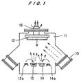
- the apparatus comprises a hermetic film deposition chamber 11 containing: a copper holder 12 for holding a substrate W on its bottom surface; vapor sources 13, 14 having respective heaters 13a, 14a and disposed below the holder 12; and an ion source 15 to irradiate ions to the substrate W from below by an oblique incident angle.
- a rotation shaft 16 is provided to rotate the substrate W so as to deposit a film uniformly, and the copper holder 12 is cooled by circulating water flowing through the rotation shaft 16 to prevent the substrate temperature from rising due to ion bombardment.
- the chamber 11 is evacuated to reach a vacuum of less than 1x10 -5 torr, and sputter cleaning of the specimen was performed using nitrogen ions irradiated at an acceleration voltage of 10 kV, ion current density of 0.2 mA/cm 2 , and an incident angle of 45 degrees.
- nitrogen ions were irradiated while controlling the current density in the ion beam source 15, and the vapor sources 13, 14 for respective Ti and additive element were heated with the heaters 13a, 14a.
- the process of deposition was continued while controlling the vaporization speed, until a film thickness of 4 ⁇ m is obtained. Film deposition conditions are shown in Table 1.
- compositions of the deposited coatings shown in Table 2 indicate that, in the first group, at least one element selected from a group of Al, Cr, Zr and Hf, is present in an amount ranging from 2 ⁇ 30 atomic %, and in the second group, either B or Si is contained in an amount ranging from 2 ⁇ 30 atomic %.
- the supply rate of additives is shown as a ratio given by, (Me deposition speed) / (Ti deposition speed).
- Coating thickness was controlled by monitoring the deposition thickness by a quartz oscillator.
- Comparative specimens were prepared in the same manner using substrates meeting a following condition: those that did not contain additive elements, those that do not form a face-centered cubic crystalline structure, those that are not within a range of lattice constants 0.414 to 0.423 nm, those that contain additives (Al, Cr, Cr, Zr and Hf) outside the range of 2 ⁇ 30 atomic % with respect to Ti, those that contain Nb and Ta in a range of 4 ⁇ 8 atomic % with respect to Ti.
- Figure 2 shows a relationship between the Vickers hardness and the size of crystallite for a number of various nitride-based coatings in the second group.
- the sliding test specimens in the second group have high values of Vickers hardness in excess of 3500 and high resistance to sliding wear.
- FIG. 3 shows a schematic view of the test apparatus comprising a trap 17, a holding case 18 for holding a substrate (specimen) W, a furnace 19 for maintaining the substrate W at a temperature, and a steam generator 20 for supplying steam to the substrate W.
- the specimen was held in the furnace for 300 hours at 450°C.
- the exposed specimen was subjected to sputtering with Ar ions for a given length of time to remove the surface layer, and the sputtered surface was examined by x-ray photoelectron spectroscopy (XPS) to examine the composition. This process was repeated to determine the oxygen content at different depth to estimate the depth of corrosion reaction. Table 3 shows the results of such tests, which indicate that those nitride-based hard coatings containing added elements exhibit resistance to high-temperature corrosion. Trial No.
- FIG 4 shows an example of the structure of a non-contact end-face seal of a steam turbine.
- a rotation shaft 22 with a shaft sleeve 23 is housed in a seal housing 21.
- the shaft sleeve 23 holds rotation rings 25 (mating rings) with keys 24.
- Each rotation ring 25 has an opposing fixed ring 26.
- the material for the rotation ring 25 is stainless steel (SUS420J2), and the sliding surface is coated with the high-temperature sliding wear resistant hard coating in the first group of this invention using the DM method.
- a groove is formed on the sliding surface of the rotation ring 25 from the high pressure side H towards the low pressure side L.
- Each fixed ring 26 is connected to a seal ring retainer 28 through a pin 27, and a spring 29 is provided between the seal ring retainer 28 and the seal housing 21.
- Each fixed ring 26 is pressed against the rotation ring 25 by means of the spring 29 and seal ring retainer 28.
- a locking plate 30 and shearing key 31 are also provided.
- the non-contact end-face seal of the above structure is operated by rotating the rotation shaft 22 so that the rotation ring 25 and the fixed ring 26 undergo relative motion and the groove provided on the rotation ring 25 swirls the fluid on the high-pressure side H and forms a fluid seal on the hermetic surface. Because of the fluid film, the hermetic surfaces are not in contact, and creates a minute space between the fixed ring 25 and the rotation ring 26.
- the seal in Figure 4 may be regarded to be in a normal compression state, and in such a case, the sliding wear resistance may be improved by applying the coating made by the DM method on the sliding surface of the rotation ring 25 in the second group.
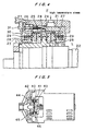
- Figure 5 shows an application of this invention to a thrust bearing in a magnetic pump.
- the thrust bearing comprises a static member 41 mounted on a dividing wall 40, and a movable member 42 facing the static member 41 and fixed on the impeller 44.
- a permanent magnet 46 is fixed on the magnetic coupling 43 via the dividing wall 40 and faces a permanent magnet 45 fixed on the impeller 44. Rotation of the magnetic coupling 43 is transmitted through the permanent magnets 46, 45 by the magnetic coupling force to the impeller 44 which rotates with a thrust support of the thrust bearing.
- the hard coating of this invention of either the group 1 or group 2 is applied to the sliding surface of the movable member 42 constructing the thrust bearing through DM method.
- the static member 41 is made of a primarily carbon-based material. By making such a thrust bearing, a superior thrust bearing having a low friction coefficient and a low wear rate of carbon is obtained.
- the sliding surface of the movable member of a radial bearing may also be coated with the hard coating of this invention and the static member may be made with a carbon-based material, thereby producing a similarly superior radial bearing.
- Figures 6A, 6B show another embodiment of this invention in which this invention is applied to a dressing tool for reconditioning a degraded surface of a chemical/mechanical polishing tool for producing a flat surface on a semiconductor substrate.
- the surface of a circular metal base 52 of the dressing tool is provided with protrusions 54 having an apex spacing of 0.3 mm and a height of 0.15 mm, and the protrusions are coated with the hard coating 56 of this invention in the first or second group using the DM method to produce surface protrusions having high hardness.
- Such a dressing tool exhibits strong bonding between the base 52 and the hard coating 56 while maintaining the same or superior resistance to wear and sliding friction compared with the conventional dressing tool shown in Figure 6C made by imbedding diamond particles 58 in an electro plated metal matrix 60, resulting in overall higher strength and durability.
- metal materials were used as a substrate, this invention is not limited to metal substrates, and super-hard alloys, ceramics may also be used to produced the same results.
- movable members of a bearing unit was made of metals, super-hard alloy or ceramic materials, and the hard coating of this invention was applied to the sliding surface of the member.
- the static member may be made of metals, super-hard alloys or ceramic materials, and the hard coating of this invention may be applied to the sliding surface and the movable member may be made of a carbon-based material.
- a material to be paired with sliding member having the hard coating of this invention was either resin-infiltrated hard carbon or hard carbon alone, but the pairing material is not limited to such a combination.
- a wide variety of carbon-based material can be used, including carbon-infiltrated materials.
- Carbon containing material may include carbon-based composite material (carbon fiber reinforced composite material, carbon composite material), carbon steel, cast irons, carbide compounds (SiC, Cr 3 C 4 , TiC and the like), and carbon-group coatings (DLC film, TiC coating).
- the first group sliding member of this invention provides a hard coating for high-temperature sliding application having improved resistance to high-temperature corrosion while maintaining the excellent wear resistance and low friction properties of TiN coating. Also, according to the second group sliding member of this invention, the hardness of TiN coating and its wear resistance are further improved so that high resistance to sliding wear demanded as a result of higher speed and pressures used in rotating machines of today.
- This invention is applicable to high-temperature sliding components such as bearings and seals used in rotating machines operating high-temperature such as steam turbines, gas turbines, or to those elements such as cutting tools that require high resistance to wear and low friction properties.
Description
- This invention relates to a high-temperature sliding member and a method for manufacturing the sliding member for use in bearings and seals in high-temperature rotating machines such as steam turbines and gas turbines, or to a sliding member that is suitable for applications requiring wear resistance and low friction such as cutting tools.
- Application of a ceramic coating to improve wear resistance and corrosion resistance of bearings and seals made of metal materials is widely practiced. Materials used for making such ceramic coatings include titanium nitrides (TiN), titanium carbides (TiC), chromium nitrides (CrN), boron nitrides (BN), and diamond-like carbon (DLC). Among these, TiN and CrN are already widely applied industrially as hard coatings on metal molds and cutting tools.
- As conventional methods for making such hard coatings, following surface improvement techniques are on the table: ion plating method including physical vapor deposition (PVD) or chemical vapor deposition (CVD), sputter deposition, plasma CVD and ion implantation. In particular, dynamic ion beam mixing (DM) method, which combines the vapor deposition method with the ion implantation technology is receiving keen interest, because the coating can bond tightly to the substrate and the coatings can be produced at low processing temperatures.
- One of the ceramic coatings that is widely in use is TiN, which is a typical substance forming an interstitial solid solution compound, is known to have a face-centered cubic crystalline structure. TiN has a NaCl type crystalline structure where nitrogen atoms enter in the lattices formed of Ti. The composition range of TiNx is as broad as 0.8< x <1.16, and when x is changed within this range, the lattice spacing of TiN is altered. Because of the superior resistance to wear and corrosion, TiN coating is also being used in bearings or seal components.
- For application to rotating machines operating at high temperatures, such as steam turbines and gas turbines, there has been a need for hard coatings having a superior wear resistance, a high temperature corrosion resistance as well as superior high temperature sliding properties, as operating temperatures become higher in practice today. TiN coating is being considered for such applications, but it is known from experimental results to date that, because of insufficient corrosion resistance at high temperatures of TiN coating itself, durability of TiN coating has been in doubt when TiN coating is to be exposed to high-temperature air atmosphere or high-temperature steam. Therefore, the current state of art of TiN does not permit the use of TiN coating for such applications.
- Also, for general purpose rotating machines such as pumps, there has been a tendency to increase rotational speed and operating pressure, resulting in a need for sliding components that can withstand severe operating conditions of high loads and high peripheral speeds. Conventional TiN coatings has become known to be inappropriate for such applications that present severe sliding conditions, because of inadequate hardness and wear resistance of TiN coating itself.
- Regarding the prior art, reference may also be had to the following documents:
- MUENZ W-D: 'TITANIUM ALUMINIUM NITRIDE FILMS: A NEW ALTERNATIVE TO TIN COATINGS' JOURNAL OF VACUUM SCIENCE AND TECHNOLOGY: PART A, US, AMERICAN INSTITUTE OF PHYSICS, NEW YORK, vol. 4, no. 6, November 1986 (1986-11), page 2717-2725, XP002064735, ISSN: 0734-2101;
- VAZ F ET AL: 'Physical, structural and mechanical characterization of Ti1-xSixNy films' 25TH INTERNATIONAL CONFERENCE ON METALLURGICAL COATINGS AND THIN FILMS, SAN DIEGO, CA, USA, 27 APRIL-1 MAY 1998, vol. 108-109, no. 1-3, pages 236-240, XP000869552, Surface and Coatings Technology, 10 Oct. 1998, Elsevier, Switzerland, ISSN:0257-8972;
- TAKANO I ET AL: 'Formation of Ti-Al-N thin films by the dynamic ion mixing method' 9TH INTERNATIONAL CONFERENCE ON SURFACE MODIFICATION OF METALS BY ION BEAMS, SAN SEBASTIAN, SPAIN, 4-8 SEPT. 1995, vol. 84, no. 1-3, pages 409-413, XP000869550, Surface and Coatings Technology, Oct. 1996, Elsevier, Switzerland, ISSN: 0257-8972;
- SHEW B-Y ET AL: 'Effects of r.f. bias and nitrogen flow rates on the reactive sputtering of TiAlN films' THIN SOLID FILMS, CH, ELSEVIERSEQUOIA S.A. LAUSANNE, vol. 293, no. 1-2, 1997, page 212-219, XP004080859, ISSN: 0040-6090;
- PATENT ABSTRACTS OF JAPAN vol. 018, no. 014 (P-1672), 11 January 1994 & JP 05 250770 A; and
- US-A-5 731 079
- This invention was made to solve the problems outlined above, and an object is to provide a sliding member that can resist high-temperature corrosion while retaining the superior wear resistance and low frictional properties of TiN coating. Another object is to provide a sliding member having superior sliding properties to meet the needs of rotating machines operating at high rotational speeds and high pressures, by further improving the superior wear resistance and low frictional properties of TiN coating.
- This invention relates to a sliding member comprising a substrate and a hard coating formed on the substrate, wherein the hard coating comprises a nitride-based material containing substantially TiN and at least one element selected from the group consisting of Cr, Zr and Hf, and having a face-centered cubic crystalline structure with a lattice constant ranging from 0.414 to 0.423 nm in a crystal of the nitride-based material.
- For the purpose of improving the resistance of TiN coatings to high temperature corrosion and oxidation, the inventors have been investigating technologies for obtaining nitride-based coatings containing elements other than Ti and N as well as methods for producing such products. That is, the primary object is to improve the resistance to high-temperature corrosion without losing the excellent sliding properties of TiN (wear resistance and low friction coefficient) by developing technologies for producing nitride-based thin films containing elements other than Ti and N. The result is a discovery that such a material has a face-centered cubic crystalline structure and contains substantially TiN and at least one element selected from the group containing Al, Cr, Zr and Hf, and that the lattice constant should be less than 0.423 nm, because if it exceeds this value, Vickers hardness becomes no more than 2000 and wear resistance becomes insufficient. These materials may also be used generally where sliding resistant properties are required.
- It is suggested that a nitride-based material of this invention, which substantially comprises TiN but also containing at least one of Al, Cr, Zr and Hf, is a material in which some sites of Ti in a face-centered cubic crystalline structure is substituted by at least one of the elements selected from the group consisting of Al, Cr, Zr and Hf, and also has a face-centered cubic crystalline structure.
- Investigations to date have demonstrated that the object is achieved when the nitride-based material has a face-centered cubic crystalline structure, the lattice constant is between 0.414 to 0.423 nm, the Vickers hardness of the material is not less than 2500 when the crystallite size of the nitride-based material is optimized, and has the following composition, excepting inevitable impurities such as carbon, oxygen, etc.
- A preferable chemical composition of a sliding member made of the nitride-based material is defined in a formula, excepting inevitable impurities: Ti(100-x)Mex nitride compound, where Me represents at least one element selected from the group consisting of Al, Cr, Zr and Hf, and x is in a range given by a relation: 2 atomic %≦ x ≦30 atomic %.
- Such a member may be made by the DM method, which allows metallic elements, Ti and additives, to be vapor deposited on a substrate in a vacuum while implanting nitrogen ions into the deposit. This method enables to produce a coated product having the coating adhering tightly to the substrate in a relatively low temperature process. It is preferable that the substrate have a low coefficient of thermal expansion of not more than 11x10-6 so as to produce tight bonding, which can be met by stainless steels, such as SUS420J2 or SUS630, or nickel-based alloys such as Incoloy 909.
- It is preferable that the acceleration voltage for the ion beam be less than 40 kV, because a higher acceleration voltage requires a large sized acceleration device, leading to a higher processing cost and a need for radiation protection. On the other hand, if the acceleration voltage is less than 1 kV, coating does not bond tightly to the substrate so that the product is not suitable for high-temperature sliding applications.
- The results of x-ray diffraction measurements suggest that the preferred crystallite size is several nm to 100 nm. Thickness of the hard coating may be adjusted for each application but it is preferable that the thickness be less than several tens of micrometers because of cost and residual stress considerations.
- The proportion of additives during the process of making the hard coating using the DM method can be adjusted by controlling the evaporation rate of Ti and the additive elements respectively. The face-centered cubic crystalline structure of TiN is produced by entering of nitrogen atoms in the Ti lattice as interstitial solid solution. When one or more of the elements Al, Cr, Zr or Hf is added to TiN, the face-centered cubic crystalline structure of TiN becomes irregular as the concentration of the additive element increases, and ultimately reaches an amorphous state or attains other crystalline structures. Therefore, to retain wear resistance and lower coefficient of friction, it is preferable that the total concentration of additive elements be not more than 30 atomic %. Also, studies to date indicate that the resistance to high-temperature corrosion is increased as the concentration of the additive element is increased, but it is preferable that the lower limit of concentration be determined so as to enable customizing the product to application conditions, in terms of the severity of corrosion of high-temperature steam or high-temperature air.
- It is preferable that the crystals be oriented to (111) planes. It is possible to orient the crystals to (111) planes during the DM method, by controlling the implantation conditions of the nitrogen ion beam such as, for example, acceleration voltage, current density, implantation energy (W/cm2), and the beam incidence angle.
- On the other hand, the inventors have also developed a nitride-based material that is useable in sliding applications that do not demand high temperature strength. Such a sliding member comprises a substrate and a hard coating formed on the substrate, wherein the hard coating comprises a nitride-based material containing substantially TiN and at least one element selected from a group consisting of B and Si, and having a face-centered cubic crystalline structure comprising crystallites of an average size of not more than 9 nm. The process leading to such a concept is outlined below.
- For the purpose of improving the hardness of TiN coatings and wear resistance, the inventors have been investigating technologies for obtaining nitride-based coatings containing elements other than Ti and N as well as methods for producing such products. That is, the primary object is to improve the hardness and wear resistance by developing technologies for producing nitride-based thin films containing elements other than Ti and N. The result is a discovery that such a material has a face-centered cubic crystalline structure and contains substantially TiN and at least one element selected from the group containing B and Si, and Vickers hardness is higher than 3000 when the crystallite size is not more than 9 nm, and has the following composition, excepting inevitable impurities such as carbon, oxygen, etc.
- A sliding member made of a second group of nitride-based materials has a chemical composition defined in a formula, excepting inevitable impurities: Ti(100-x)Mex nitride compound where Me represents at least one element selected from the group consisting of B and Si, and x is in a range given by a relation: 2 atomic %≦ x ≦30 atomic %.
- As in the first group, such a member may be produced by the DM method, which allows metallic elements, Ti and additives, to be vapor deposited on a substrate in a vacuum while implanting nitrogen ions in the deposit. This method enables to produce a coated product having the coating adhering tightly to the substrate in a relatively low temperature process. It is preferable that the substrate have a low coefficient of thermal expansion of not more than 11x10-6 so as to produce tight bonding, which can be met by stainless steels, such as SUS420J2 or SUS630, or nickel-based alloys such as Incoloy 909. The substrate may include other steel materials than the above referred. Also, for the purpose of making wear resistant parts or cutting tools, various ceramic materials such as SiC, Si3N4 and Al2O3 as well as super-hard alloys such as WC may be used.
- It is preferable that the acceleration voltage for the ion beam be less than 40 kv, because a higher acceleration voltage requires a large sized acceleration device, leading to higher processing cost and a need for radiation protection. On the other hand, if the acceleration voltage is less than 1 kV, coating does not bond tightly to the substrate, and the product is not suitable for sliding applications. Thickness of the hard coating may be adjusted for each application but it is preferable that the thickness be less than several tens of micrometers because of cost and residual stress considerations.
- The proportion of additives during the process of making the hard coating using the DM method can be adjusted by controlling the evaporation rate of Ti and the additive elements. The face-centered cubic crystalline structure of TiN is produced by entering of nitrogen atoms in the Ti lattice as interstitial solid solution. When one or more of the elements B and Si is added to TiN, as the concentration of the additive element increases, face-centered cubic crystalline structure of TiN becomes irregular, and ultimately attains other crystalline structures. Therefore, to retain superior wear resistance and lower coefficient of friction, it is preferable that the total concentration of additive elements be not more than 30 atomic %. Also, studies to date indicate that the hardness and wear resistance are increased as the concentration of the additive element is increased, but it is preferable that the lower limit of concentration be determined so as to enable customizing the product to the severity of sliding conditions.
- It is preferable that the crystals be oriented to (111) planes. It is possible to orient the crystals to (111) planes during the DM method, by controlling the implantation conditions of the nitrogen ion beam such as, for example, acceleration voltage, current density, implantation energy (W/cm2), and the beam incidence angle.
- In the manufacturing process of the above described sliding members, it is permissible to form a hard coating on the substrate by simultaneously depositing in a vacuum Ti and at least one element selected from the group consisting of Al, Cr, Zr, Hf, B and Si on the substrate while irradiating the substrate with ion beams containing substantially nitrogen ions.
- Another aspect of the present invention is a sliding mechanism comprising a combination of a movable member and a static member, wherein either the movable member or the static member is made of a sliding member according to any of claims 1 to 4, or made by a method according to claim 5, and a remaining member is made of a material containing carbon. The material containing carbon may be a material containing substantially carbon, a material infiltrated with carbon or a thin film containing carbon.
- In a sliding member according to any of claims 1 to 4, a method according to claim 5 or a sliding mechanism according to claim 6 or 7, the substrate may be a metal material.
- Another aspect of the present invention is a dressing tool comprising a sliding member according to any of claims 1 to 4, or comprising a sliding member made by a method according to claim 5.
-
- Figure 1 is a schematic diagram of an apparatus for making the hard coating of this invention;
- Figure 2 is a graph showing the crystallite size and Vickers hardness values;
- Figure 3 is a schematic diagram of a high-temperature steam testing apparatus;
- Figure 4 is a diagram of a structure of a non-contacting end-face seal for a steam turbine;
- Figure 5 is a diagram of a magnetic pump having the sliding member of this invention applied to a thrust bearing; and
- Figure 6 is a diagram of a dressing tool having the sliding member of this invention.
-
- This invention will be illustrated in terms of the preferred embodiments described in the following.
- First, a dynamic ion beam mixing (DM) film deposition apparatus will be explained with reference to Figure 1. The apparatus comprises a hermetic
film deposition chamber 11 containing: acopper holder 12 for holding a substrate W on its bottom surface;vapor sources respective heaters holder 12; and anion source 15 to irradiate ions to the substrate W from below by an oblique incident angle. Arotation shaft 16 is provided to rotate the substrate W so as to deposit a film uniformly, and thecopper holder 12 is cooled by circulating water flowing through therotation shaft 16 to prevent the substrate temperature from rising due to ion bombardment. - Using this film deposition apparatus, comparative tests were carried out using two types of substrates, SUS4202J2 steel and Incoloy 909, by depositing films according to the following procedure. In the first group of test specimens, at least one element selected from a group of metals, Al, Cr, Zr and Hf, is contained in Ti in a ratio of 2∼30 atomic %, and in a second group of test specimens, at least one element selected from a group of elements B and Si, is contained in Ti in a ratio of 2∼30 atomic %. The substrate W is pre-treated by polishing the specimen surface to a mirror polish to attain an average surface roughness of less than 0.05 µm, and the process is finished by ultrasonic cleaning in alcohol. The cleaned substrate W was attached to the
holder 12 of the DM apparatus shown in Figure 1. - First, the
chamber 11 is evacuated to reach a vacuum of less than 1x10⁻⁵ torr, and sputter cleaning of the specimen was performed using nitrogen ions irradiated at an acceleration voltage of 10 kV, ion current density of 0.2 mA/cm2, and an incident angle of 45 degrees. Next, nitrogen ions were irradiated while controlling the current density in theion beam source 15, and thevapor sources heaters Conditions for making hard coatings Ti deposition speed 0.1∼3.0 nm/s Additive element first group, one of Zr, Hf, Nb, Ta, Cr or Al second group, one of B or Si Additive deposition speed 0.1~0.5 nm/s Nitrogen incident angle 45 degrees Acceleration voltage 10 kV Beam current density 0.05∼0.5 mA/cm2 Deposition pressure 5x10⁻⁶∼5x10⁻⁵ torr - The compositions of the deposited coatings shown in Table 2 indicate that, in the first group, at least one element selected from a group of Al, Cr, Zr and Hf, is present in an amount ranging from 2∼30 atomic %, and in the second group, either B or Si is contained in an amount ranging from 2~30 atomic %. In this table, the supply rate of additives is shown as a ratio given by, (Me deposition speed) / (Ti deposition speed). Coating thickness was controlled by monitoring the deposition thickness by a quartz oscillator. Comparative specimens were prepared in the same manner using substrates meeting a following condition: those that did not contain additive elements, those that do not form a face-centered cubic crystalline structure, those that are not within a range of lattice constants 0.414 to 0.423 nm, those that contain additives (Al, Cr, Cr, Zr and Hf) outside the range of 2∼30 atomic % with respect to Ti, those that contain Nb and Ta in a range of 4∼8 atomic % with respect to Ti.
Trial No. Additive Me Supply Ratio Me/Ti Conc. of Me (at%) Hardness (Hv) Cryst. Struc. TiN Latt. Plane Latt. Const. (nm) Case 1 Al 0.05 3.9 2500 FCC (111) 0.4152 Case 2 Al 0.10 9.1 2550 FCC (111) 0.4159 Case 3 Cr 0.03 4.4 2500 FCC (111) 0.4166 Case 4 Cr 0.05 5.9 3150 FCC (111) 0.4162 Case 5 Cr 0.10 13 2700 FCC (111) 0.4152 Case 6 Cr 0.27 26 2850 FCC (111) 0.4200 Case 7 Hf 0.03 3.0 2650 FCC (111) 0.4218 Case 8 Hf 0.05 5.3 3500 FCC (111) 0.4200 Case 9 Hf 0.27 21 2650 FCC (111) 0.4200 Case 10Zr 0.05 5.3 2550 FCC (111) 0.4164 Case 11 B 0.05 7.4 4600 FCC (111) Case 12 B 0.03 5.8 4300 FCC (111) Case 13 B 0.36 22.8 4400 FCC (111) Case 14Si 0.05 4.1 4600 FCC (111) comp. 1 none 0 0 3500 FCC (111) 0.4162 comp. 2 Al 0.30 35 2650 FCC (111) 0.4218 comp. 3 Al 0.50 52 1250 comp. 4 Cr 0.50 61 2050 comp. 5 Hf 0.10 11 2550 FCC (111) 0.4235 comp. 6 Hf 0.27 21 2250 FCC (111) 0.4261 comp. 7 Hf 0.50 54 3050 comp. 8 Nb 0.05 5.5 3250 FCC (111) 0.4178 comp. 9 Ta 0.05 5.7 2400 FCC (111) 0.4193 - The properties of the various hard coatings thus obtained are also shown in Table 2. In the first group, all the hard coatings exhibited a (111) preferred orientation and the spacing between (111) planes remained within a range of 0.239∼0.242 nm. The lattice constant obtained from these values of the inter-planar spacings indicated a range of 0.414∼0.419 nm.
- Also, Figure 2 shows a relationship between the Vickers hardness and the size of crystallite for a number of various nitride-based coatings in the second group. The results of x-ray diffraction studies of the various nitride-based coatings indicated that the coatings are face-centered cubic, and have a (111) preferred orientation. The size of crystallite was obtained from a relation:
- Next, TiN coatings of 0.1∼3 µm thickness were first grown on the substrate in the apparatus shown in Figure 1 without adding any additives, and then using the method described above, various elements were added to the nitride-based coating to obtain a final thickness of about 5 µm. The specimens were then subjected to high-temperature steam exposure tests. Figure 3 shows a schematic view of the test apparatus comprising a
trap 17, a holdingcase 18 for holding a substrate (specimen) W, afurnace 19 for maintaining the substrate W at a temperature, and asteam generator 20 for supplying steam to the substrate W. The specimen was held in the furnace for 300 hours at 450°C. - The exposed specimen was subjected to sputtering with Ar ions for a given length of time to remove the surface layer, and the sputtered surface was examined by x-ray photoelectron spectroscopy (XPS) to examine the composition. This process was repeated to determine the oxygen content at different depth to estimate the depth of corrosion reaction. Table 3 shows the results of such tests, which indicate that those nitride-based hard coatings containing added elements exhibit resistance to high-temperature corrosion.
Trial No. Additives Me (atomic %) Atomic Concentration Resistance to High-temperature Corrosion Case 1 Al 3.9 o ○ Case 4 Cr 4.4 o ○ Case 8 Hf 3.0 o ○ Case 10Zr 5.3 Δ Comparison 1 none 0 Δ Comparison 8 Nb 5.5 × Comparison 9 Ta 5.7 × ×: corrosion thickness in excess of 0.3 µm Δ: corrosion thickness in excess of 0.2 µm, less than 0.3 µm ○: corrosion thickness in excess of 0.1 µm, less than 0.2 µm o ○: corrosion thickness less than 0.1 µm - Next, an application of this invention to a mating ring in a steam turbine will be explained. Figure 4 shows an example of the structure of a non-contact end-face seal of a steam turbine. In Figure 4, a
rotation shaft 22 with ashaft sleeve 23 is housed in aseal housing 21. Theshaft sleeve 23 holds rotation rings 25 (mating rings) withkeys 24. Eachrotation ring 25 has an opposing fixedring 26. The material for therotation ring 25 is stainless steel (SUS420J2), and the sliding surface is coated with the high-temperature sliding wear resistant hard coating in the first group of this invention using the DM method. Although not shown in the drawing, a groove is formed on the sliding surface of therotation ring 25 from the high pressure side H towards the low pressure side L. - Each fixed
ring 26 is connected to aseal ring retainer 28 through apin 27, and aspring 29 is provided between theseal ring retainer 28 and theseal housing 21. Each fixedring 26 is pressed against therotation ring 25 by means of thespring 29 andseal ring retainer 28. Here, a lockingplate 30 and shearing key 31 are also provided. - The non-contact end-face seal of the above structure is operated by rotating the
rotation shaft 22 so that therotation ring 25 and the fixedring 26 undergo relative motion and the groove provided on therotation ring 25 swirls the fluid on the high-pressure side H and forms a fluid seal on the hermetic surface. Because of the fluid film, the hermetic surfaces are not in contact, and creates a minute space between the fixedring 25 and therotation ring 26. Here, the seal in Figure 4 may be regarded to be in a normal compression state, and in such a case, the sliding wear resistance may be improved by applying the coating made by the DM method on the sliding surface of therotation ring 25 in the second group. - Figure 5 shows an application of this invention to a thrust bearing in a magnetic pump. In Figure 5, the thrust bearing comprises a
static member 41 mounted on a dividingwall 40, and amovable member 42 facing thestatic member 41 and fixed on theimpeller 44. Apermanent magnet 46 is fixed on themagnetic coupling 43 via the dividingwall 40 and faces apermanent magnet 45 fixed on theimpeller 44. Rotation of themagnetic coupling 43 is transmitted through thepermanent magnets impeller 44 which rotates with a thrust support of the thrust bearing. - The hard coating of this invention of either the group 1 or group 2 is applied to the sliding surface of the
movable member 42 constructing the thrust bearing through DM method. Thestatic member 41 is made of a primarily carbon-based material. By making such a thrust bearing, a superior thrust bearing having a low friction coefficient and a low wear rate of carbon is obtained. Although not shown in the drawing, the sliding surface of the movable member of a radial bearing may also be coated with the hard coating of this invention and the static member may be made with a carbon-based material, thereby producing a similarly superior radial bearing. - Figures 6A, 6B show another embodiment of this invention in which this invention is applied to a dressing tool for reconditioning a degraded surface of a chemical/mechanical polishing tool for producing a flat surface on a semiconductor substrate. The surface of a
circular metal base 52 of the dressing tool is provided withprotrusions 54 having an apex spacing of 0.3 mm and a height of 0.15 mm, and the protrusions are coated with thehard coating 56 of this invention in the first or second group using the DM method to produce surface protrusions having high hardness. - Such a dressing tool exhibits strong bonding between the base 52 and the
hard coating 56 while maintaining the same or superior resistance to wear and sliding friction compared with the conventional dressing tool shown in Figure 6C made by imbeddingdiamond particles 58 in an electro platedmetal matrix 60, resulting in overall higher strength and durability. - It should be noted that although metal materials were used as a substrate, this invention is not limited to metal substrates, and super-hard alloys, ceramics may also be used to produced the same results.
- Also, in the above embodiments, movable members of a bearing unit was made of metals, super-hard alloy or ceramic materials, and the hard coating of this invention was applied to the sliding surface of the member. However, the static member may be made of metals, super-hard alloys or ceramic materials, and the hard coating of this invention may be applied to the sliding surface and the movable member may be made of a carbon-based material.
- Also, in the above embodiments, a material to be paired with sliding member having the hard coating of this invention was either resin-infiltrated hard carbon or hard carbon alone, but the pairing material is not limited to such a combination. A wide variety of carbon-based material can be used, including carbon-infiltrated materials. Carbon containing material may include carbon-based composite material (carbon fiber reinforced composite material, carbon composite material), carbon steel, cast irons, carbide compounds (SiC, Cr3C4, TiC and the like), and carbon-group coatings (DLC film, TiC coating).
- As explained above, according to the first group sliding member of this invention provides a hard coating for high-temperature sliding application having improved resistance to high-temperature corrosion while maintaining the excellent wear resistance and low friction properties of TiN coating. Also, according to the second group sliding member of this invention, the hardness of TiN coating and its wear resistance are further improved so that high resistance to sliding wear demanded as a result of higher speed and pressures used in rotating machines of today.
- This invention is applicable to high-temperature sliding components such as bearings and seals used in rotating machines operating high-temperature such as steam turbines, gas turbines, or to those elements such as cutting tools that require high resistance to wear and low friction properties.
Claims (11)
- A sliding member comprising a substrate and a hard coating formed on said substrate, wherein said hard coating comprises a nitride-based material containing titanium nitride and Cr, and having a face-centered cubic crystalline structure with a lattice constant ranging from 0.414 to 0.423 nm in a crystal of said nitride-based material.
- A sliding member comprising a substrate and a hard coating formed on said substrate, wherein said hard coating comprises a nitride-based material containing titanium nitride and B, and having a face-centered cubic crystalline structure comprising crystallites of an average size of not more than 9 nm.
- A sliding member comprising a substrate and a hard coating formed on said substrate, wherein said hard coating comprises a nitride-based material containing titanium nitride and at least one element selected from the group consisting of Zr and Hf, and having a face-centered cubic crystalline structure with a lattice constant ranging from 0.414 to 0.423 nm in a crystal of said nitride-based material.
- A sliding member according to any of claims 1 to 3, wherein said nitride-based material has a chemical composition defined in a formula, excepting inevitable impurities:
- A method for making a sliding member according to any of claims 1 to 4, comprising the steps of: forming a hard coating on said substrate by simultaneously depositing in a vacuum Ti and at least one element selected from the group consisting of Cr, Zr, Hf and Si on said substrate while irradiating said substrate with ion beams containing substantially nitrogen ions.
- A sliding mechanism comprising a combination of a movable member and a static member, wherein either said movable member or said static member is made of a sliding member according to any of claims 1 to 4, or made by a method according to claim 5, and the remaining member is made of a material containing carbon.
- A sliding mechanism according to claim 6, wherein said material containing carbon is a material containing substantially carbon, a material infiltrated with carbon or a thin film containing carbon.
- A sliding member according to any of claims 1 to 3, wherein said substrate is a metal material.
- A method according to claim 5, wherein said substrate is a metal material.
- A sliding mechanism according to claim 6 or 7, wherein said substrate is a metal material.
- A dressing tool comprising a sliding member according to any of claims 1 to 4, or comprising a sliding member made by a method according to claim 5.
Applications Claiming Priority (5)
| Application Number | Priority Date | Filing Date | Title |
|---|---|---|---|
| JP30225998 | 1998-10-23 | ||
| JP30226098 | 1998-10-23 | ||
| JP30226098A JP3838796B2 (en) | 1998-10-23 | 1998-10-23 | Hard film for sliding members |
| JP30225998A JP3797807B2 (en) | 1998-10-23 | 1998-10-23 | Hard film for high temperature sliding members |
| PCT/JP1999/005838 WO2000024947A1 (en) | 1998-10-23 | 1999-10-22 | Sliding member and manufacturing method therefor |
Publications (2)
| Publication Number | Publication Date |
|---|---|
| EP1135541A1 EP1135541A1 (en) | 2001-09-26 |
| EP1135541B1 true EP1135541B1 (en) | 2005-06-08 |
Family
ID=26563041
Family Applications (1)
| Application Number | Title | Priority Date | Filing Date |
|---|---|---|---|
| EP99949366A Expired - Lifetime EP1135541B1 (en) | 1998-10-23 | 1999-10-22 | Sliding member and manufacturing method therefor |
Country Status (5)
| Country | Link |
|---|---|
| US (1) | US6767657B1 (en) |
| EP (1) | EP1135541B1 (en) |
| KR (1) | KR100632425B1 (en) |
| DE (1) | DE69925753T2 (en) |
| WO (1) | WO2000024947A1 (en) |
Families Citing this family (11)
| Publication number | Priority date | Publication date | Assignee | Title |
|---|---|---|---|---|
| US6558822B2 (en) | 2000-05-25 | 2003-05-06 | Ebara Corporation | Cr-containing titanium nitride film |
| EP1316627B1 (en) * | 2001-11-28 | 2006-04-05 | METAPLAS IONON Oberflächenveredelungstechnik GmbH | Hard coating coated parts |
| US7220098B2 (en) * | 2003-05-27 | 2007-05-22 | General Electric Company | Wear resistant variable stator vane assemblies |
| US7455890B2 (en) * | 2003-08-05 | 2008-11-25 | General Electric Company | Ion implantation of turbine engine rotor component |
| US20050238801A1 (en) * | 2004-04-27 | 2005-10-27 | Chia-Te Lin | Method for fabricating an alignment layer for liquid crystal applications |
| US20070045966A1 (en) * | 2005-08-31 | 2007-03-01 | Caterpillar Inc. | Coatings for metal-metal seal surfaces |
| WO2007039982A1 (en) * | 2005-09-30 | 2007-04-12 | Konica Minolta Opto, Inc. | Resin molding apparatus |
| US20070148428A1 (en) * | 2005-12-28 | 2007-06-28 | Akebono Brake Industry Co., Ltd. | Friction material and manufacturing method thereof |
| CN102605321A (en) * | 2011-01-24 | 2012-07-25 | 鸿富锦精密工业(深圳)有限公司 | Film plating piece and preparation method thereof |
| BR112013032280B1 (en) | 2011-06-17 | 2020-11-03 | Kabushiki Kaisha Kobe Seiko Sho (Kobe Steel, Ltd.) | limb covered with hard coating |
| CN114059023B (en) * | 2021-10-29 | 2022-09-23 | 东莞市华升真空镀膜科技有限公司 | Coating, method for producing the same and device |
Family Cites Families (11)
| Publication number | Priority date | Publication date | Assignee | Title |
|---|---|---|---|---|
| JPS55120936A (en) * | 1979-02-27 | 1980-09-17 | Hitachi Metals Ltd | Covered tool |
| JPS6115967A (en) | 1984-06-29 | 1986-01-24 | Sumitomo Electric Ind Ltd | Surface treatment |
| SE453369C (en) * | 1986-05-28 | 1989-08-08 | Vni Instrument Inst | Durable Coating for Cutting Tools and Procedure for Coating |
| JPH05250770A (en) * | 1992-03-03 | 1993-09-28 | Nissin Electric Co Ltd | Magnetic head and fabrication thereof |
| JP3198636B2 (en) * | 1992-06-30 | 2001-08-13 | 三菱マテリアル株式会社 | Cutting tool made of cemented carbide with graded hard layer coating |
| DE4317758A1 (en) * | 1993-05-28 | 1994-12-01 | Berliner Schreibfeder Gmbh | Pen nib and method for its production |
| WO1995005497A1 (en) * | 1993-08-16 | 1995-02-23 | Sumitomo Electric Industries, Ltd. | Cemented carbide alloy for cutting tool and coated cemented carbide alloy |
| JP3291552B2 (en) | 1994-05-30 | 2002-06-10 | 独立行政法人産業技術総合研究所 | Seal or bearing |
| EP0701982B1 (en) * | 1994-09-16 | 2002-07-03 | Sumitomo Electric Industries, Limited | Layered film made of ultrafine particles and a hard composite material for tools possessing the film |
| US5681653A (en) | 1995-05-11 | 1997-10-28 | Si Diamond Technology, Inc. | Diamond cutting tools |
| WO1997007260A1 (en) * | 1995-08-19 | 1997-02-27 | Widia Gmbh | Composite body and process for its production |
-
1999
- 1999-10-22 US US09/807,436 patent/US6767657B1/en not_active Expired - Lifetime
- 1999-10-22 KR KR1020017004900A patent/KR100632425B1/en active IP Right Grant
- 1999-10-22 EP EP99949366A patent/EP1135541B1/en not_active Expired - Lifetime
- 1999-10-22 DE DE69925753T patent/DE69925753T2/en not_active Expired - Lifetime
- 1999-10-22 WO PCT/JP1999/005838 patent/WO2000024947A1/en active IP Right Grant
Also Published As
| Publication number | Publication date |
|---|---|
| DE69925753T2 (en) | 2006-03-16 |
| US6767657B1 (en) | 2004-07-27 |
| KR20010080244A (en) | 2001-08-22 |
| WO2000024947A1 (en) | 2000-05-04 |
| DE69925753D1 (en) | 2005-07-14 |
| EP1135541A1 (en) | 2001-09-26 |
| KR100632425B1 (en) | 2006-10-09 |
Similar Documents
| Publication | Publication Date | Title |
|---|---|---|
| KR100858855B1 (en) | Thin wear resistant coating | |
| Berger et al. | Low stress TiB2 coatings with improved tribological properties | |
| Ehrhardt | New developments in the field of superhard coatings | |
| Neuville et al. | Hard carbon coatings: the way forward | |
| EP1135541B1 (en) | Sliding member and manufacturing method therefor | |
| KR100787510B1 (en) | Cr-CONTAINING TITANIUM NITRIDE FILM | |
| US5955212A (en) | Superhard film-coated member and method of manufacturing the same | |
| Dong et al. | Microstructural effects on the high-temperature steam oxidation resistance of magnetron sputtered Cr-Al-Si-N quaternary coatings on zirconium coupons | |
| US5182238A (en) | Protective layer of hard material with homogeneous distribution of elements | |
| CN114196914B (en) | Carbide high-entropy ceramic material, carbide ceramic layer and preparation method and application thereof | |
| Bunshah et al. | Hard coatings | |
| JP3838796B2 (en) | Hard film for sliding members | |
| Bai et al. | Effects of deposition parameters on microstructure of CrN/Si3N4 nanolayered coatings and their thermal stability | |
| JP3797807B2 (en) | Hard film for high temperature sliding members | |
| JP4245827B2 (en) | Cr-containing titanium nitride film | |
| JP2001152320A (en) | Sliding member | |
| JP4388152B2 (en) | Thin film laminate covering member | |
| Moretti et al. | Duplex treatment on AISI D2 tool steel: plasma nitriding and reactive deposition of TiN and TiAlN films via magnetron sputtering | |
| Su et al. | Mechanical and Tribological Properties of NbAl, NbAlN, and NbAIN-CH Coatings Deposited using Various Niobium Target Currents and Acetylene Flow Rates | |
| JP3787586B2 (en) | Amorphous boron nitride thin film-coated sliding member and method for manufacturing the sliding member | |
| Upadhya | Properties and performance of plasma-assisted physically vapor-deposited TiC coatings | |
| Lugscheider et al. | Influence on Phase Configuration of Protective MCrAlY-Coatings Deposited by Advanced PVD Techniques and Determined by High Temperature XRD | |
| Bhushan | Structural and compositional characterization of Rf sputter-deposited Ni-Cr+ Cr2O3 films | |
| He et al. | Effects of the Ti/Al atomic ratio on the properties of gradient (Ti, Al) N films synthesized by ion beam assisted deposition | |
| Benarioua et al. | Carbide formation in titanium coatings deposited on carbon steel |
Legal Events
| Date | Code | Title | Description |
|---|---|---|---|
| PUAI | Public reference made under article 153(3) epc to a published international application that has entered the european phase |
Free format text: ORIGINAL CODE: 0009012 |
|
| 17P | Request for examination filed |
Effective date: 20010419 |
|
| AK | Designated contracting states |
Kind code of ref document: A1 Designated state(s): AT BE CH CY DE DK ES FI FR GB GR IE IT LI LU MC NL PT SE |
|
| 17Q | First examination report despatched |
Effective date: 20030326 |
|
| RBV | Designated contracting states (corrected) |
Designated state(s): CH DE FR GB IT LI |
|
| GRAP | Despatch of communication of intention to grant a patent |
Free format text: ORIGINAL CODE: EPIDOSNIGR1 |
|
| GRAS | Grant fee paid |
Free format text: ORIGINAL CODE: EPIDOSNIGR3 |
|
| GRAA | (expected) grant |
Free format text: ORIGINAL CODE: 0009210 |
|
| AK | Designated contracting states |
Kind code of ref document: B1 Designated state(s): CH DE FR GB IT LI |
|
| REG | Reference to a national code |
Ref country code: GB Ref legal event code: FG4D |
|
| REG | Reference to a national code |
Ref country code: CH Ref legal event code: EP |
|
| REF | Corresponds to: |
Ref document number: 69925753 Country of ref document: DE Date of ref document: 20050714 Kind code of ref document: P |
|
| REG | Reference to a national code |
Ref country code: CH Ref legal event code: NV Representative=s name: E. BLUM & CO. PATENTANWAELTE |
|
| ET | Fr: translation filed | ||
| PLBE | No opposition filed within time limit |
Free format text: ORIGINAL CODE: 0009261 |
|
| STAA | Information on the status of an ep patent application or granted ep patent |
Free format text: STATUS: NO OPPOSITION FILED WITHIN TIME LIMIT |
|
| 26N | No opposition filed |
Effective date: 20060309 |
|
| REG | Reference to a national code |
Ref country code: CH Ref legal event code: PFA Owner name: EBARA CORPORATION Free format text: EBARA CORPORATION#11-1, HANEDA ASAHI-CHO#OHTA-KU, TOKYO 144-8510 (JP) -TRANSFER TO- EBARA CORPORATION#11-1, HANEDA ASAHI-CHO#OHTA-KU, TOKYO 144-8510 (JP) |
|
| REG | Reference to a national code |
Ref country code: FR Ref legal event code: PLFP Year of fee payment: 18 |
|
| REG | Reference to a national code |
Ref country code: FR Ref legal event code: PLFP Year of fee payment: 19 |
|
| REG | Reference to a national code |
Ref country code: FR Ref legal event code: PLFP Year of fee payment: 20 |
|
| PGFP | Annual fee paid to national office [announced via postgrant information from national office to epo] |
Ref country code: FR Payment date: 20180913 Year of fee payment: 20 |
|
| PGFP | Annual fee paid to national office [announced via postgrant information from national office to epo] |
Ref country code: DE Payment date: 20181009 Year of fee payment: 20 |
|
| PGFP | Annual fee paid to national office [announced via postgrant information from national office to epo] |
Ref country code: GB Payment date: 20181017 Year of fee payment: 20 Ref country code: IT Payment date: 20181018 Year of fee payment: 20 Ref country code: CH Payment date: 20181015 Year of fee payment: 20 |
|
| REG | Reference to a national code |
Ref country code: DE Ref legal event code: R071 Ref document number: 69925753 Country of ref document: DE |
|
| REG | Reference to a national code |
Ref country code: CH Ref legal event code: PL |
|
| REG | Reference to a national code |
Ref country code: GB Ref legal event code: PE20 Expiry date: 20191021 |
|
| PG25 | Lapsed in a contracting state [announced via postgrant information from national office to epo] |
Ref country code: GB Free format text: LAPSE BECAUSE OF EXPIRATION OF PROTECTION Effective date: 20191021 |