EP1134749A1 - Electrical cable - Google Patents
Electrical cable Download PDFInfo
- Publication number
- EP1134749A1 EP1134749A1 EP00400596A EP00400596A EP1134749A1 EP 1134749 A1 EP1134749 A1 EP 1134749A1 EP 00400596 A EP00400596 A EP 00400596A EP 00400596 A EP00400596 A EP 00400596A EP 1134749 A1 EP1134749 A1 EP 1134749A1
- Authority
- EP
- European Patent Office
- Prior art keywords
- conductors
- line
- film
- around
- protective layer
- Prior art date
- Legal status (The legal status is an assumption and is not a legal conclusion. Google has not performed a legal analysis and makes no representation as to the accuracy of the status listed.)
- Granted
Links
Images

Classifications
-
- H—ELECTRICITY
- H01—ELECTRIC ELEMENTS
- H01B—CABLES; CONDUCTORS; INSULATORS; SELECTION OF MATERIALS FOR THEIR CONDUCTIVE, INSULATING OR DIELECTRIC PROPERTIES
- H01B7/00—Insulated conductors or cables characterised by their form
- H01B7/17—Protection against damage caused by external factors, e.g. sheaths or armouring
- H01B7/18—Protection against damage caused by wear, mechanical force or pressure; Sheaths; Armouring
- H01B7/1895—Internal space filling-up means
-
- H—ELECTRICITY
- H01—ELECTRIC ELEMENTS
- H01B—CABLES; CONDUCTORS; INSULATORS; SELECTION OF MATERIALS FOR THEIR CONDUCTIVE, INSULATING OR DIELECTRIC PROPERTIES
- H01B7/00—Insulated conductors or cables characterised by their form
-
- H—ELECTRICITY
- H01—ELECTRIC ELEMENTS
- H01B—CABLES; CONDUCTORS; INSULATORS; SELECTION OF MATERIALS FOR THEIR CONDUCTIVE, INSULATING OR DIELECTRIC PROPERTIES
- H01B7/00—Insulated conductors or cables characterised by their form
- H01B7/17—Protection against damage caused by external factors, e.g. sheaths or armouring
- H01B7/18—Protection against damage caused by wear, mechanical force or pressure; Sheaths; Armouring
- H01B7/1855—Sheaths comprising helical wrapped non-metallic layers
-
- H—ELECTRICITY
- H01—ELECTRIC ELEMENTS
- H01B—CABLES; CONDUCTORS; INSULATORS; SELECTION OF MATERIALS FOR THEIR CONDUCTIVE, INSULATING OR DIELECTRIC PROPERTIES
- H01B7/00—Insulated conductors or cables characterised by their form
- H01B7/17—Protection against damage caused by external factors, e.g. sheaths or armouring
- H01B7/18—Protection against damage caused by wear, mechanical force or pressure; Sheaths; Armouring
- H01B7/186—Sheaths comprising longitudinal lapped non-metallic layers
Definitions
- the invention relates to an electrical line with at least two mutually insulated conductors that are in a common inner sheath dimensionally accurate, cylindrical outer surface are embedded, in which over the Inner sheath an electrical screen formed as a braid and an outer one above Protective layer of insulating material are arranged (DE 298 08 657 U1).
- Such lines are used, for example, for industrial machines and in the Automotive technology used for data or signal transmission. You should just producible and robust and as light as possible. To disturbances to exclude such lines with an effective electrical shield be provided. After all, they should be as simple as possible for connection purposes to be stripped or stripped.
- the known line according to DE 298 08 657 U1 mentioned at the beginning fulfills such Demands as far as possible. It consists of two with different colored insulation provided electrical wires, which lie side by side as a separating layer designated wrapping are surrounded. There is an extrusion over the separation layer generated inner jacket made of polyvinyl chloride. The inner jacket is made of a braid surrounded by tinned copper wires. An outer jacket is made of mechanical protection Polyvinyl chloride provided. The effort to manufacture this line is considerable. This applies in particular to the manufacture of the wire and separation layer Core. The separation layer must also be removed separately for contacting purposes become.
- the invention has for its object to the line described above design that it is easy to manufacture and easy to strip.
- This line can be done in a single operation with the required Establish dimensional accuracy. Because the conductors respect an insulating distance are stranded together with alternating lay direction, none will be in only one In the direction of rotating stranding baskets equipped with coils. The one because of his compressible design as an inner layer acting as a cushion layer compared to the stranding process of constant speed in a simple manner around the stranded conductors. This also applies to those in tandem then layers "screen” and "protective layer” to be applied. After one for The conductors are made without stripping Additional measures directly accessible, since the inner sheath is directly cut can be removed from the conductors.
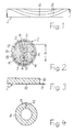
- Fig. 1 is a schematic side view of the core of an electrical line L with two Shaped stranding elements E shown, which twisted together with changing direction of lay are. Such stranding is also referred to in the technical field as "SZ stranding".
- SZ stranding In the course of the line L changes at reversal points U, one of which is shown in FIG. 1 is shown, the direction of stranding for the stranding elements E.
- Such lines are advantageously not rotating in only one direction Stranding devices required in conventional technology with one of the number of stranding elements corresponding number of coils must be equipped.
- a line 1 according to the invention has the following structure, for example:
- each of the wires 2 and 3 consists of an electrical conductor 4 and an insulation 5 surrounding the same.
- the conductors 4 preferably consist of Copper. They can be solid as a wire or as a stranded wire.
- Insulation 5 is used in a preferred embodiment, foamed material. But it can also be solid.
- the two wires 2 and 3 are with different colored insulation 5 provided. As insulation materials are for example, polyethylene and polypropylene.
- the cores 2 and 3 are made very dimensionally. They have their full length an exactly set outer diameter, which is identical for both wires. After SZ stranding has the same one twice the outer diameter of the same corresponding height H.
- the height H corresponds to the diameter of the dashed line drawn circle K at each point of the line 1 - in the longitudinal direction seen - consistently present.
- the Inner jacket 6 is made of insulating material shaped, which bears against the wires 2 and 3, fills the gusset between them and has a circular outer surface with a defined radius R.
- the distance of the outer surface of the inner shell 6 of the circle K is constant all round.
- the Inner jacket 6 consists of a mechanically stable but compressible material, for example made of foamed polyethylene, polypropylene or silicone. He can be shaped around the two wires 2 and 3 by means of an extruder.
- the inner jacket 6 is made of one shown in FIG. 3
- Band 7 made of foam material, preferably based on polyurethane, which longitudinally bent into a slotted tube 8 (FIG. 4) and thus around the two wires 2 and 3 is molded around:
- the band 7 consists of a rectangular strip 9 of foam, which is on a Carrier film 10 is attached.
- the carrier film 10 can on one side over the whole Extend the length of the band 7 to form a tab 11.
- the band 7 is formed longitudinally into the slotted tube 8 in which its two side edges lie against one another at slot 12.
- the tab 11 projects over the Slot 12 out. In the final state, it lies on the outside of the carrier film 10 and can also be used the same be glued.
- the outer contour of the slotted tube 8 has over its entire length consistent dimensions with great accuracy.
- the foam of the Strip 9 through the veins 2 and 3 z. T. considerably compressed. But he lies down without Gap formation also in the gusset between the two wires 2 and 3.
- a shielding film 13 is located above the inner jacket 6 in the line 1 shown in FIG. 2 attached, the longitudinally running with overlapping edges around the inner jacket 6 is formed around. It can be glued to the same.
- the screen film 13 is from one as a braid consisting of electrically well-conducting wires, electrical screen 14 surround. Copper wires, which are also tinned, can be used for the screen 14 could be.
- An outer protective layer 15 is applied over the screen 14, which consists of a first film applied lengthways with overlapping edges and one around the same helical, wrapped with overlap second film.
- the Screen film 13 can be dispensed with. If a screen film 13 is used, can for example an aluminum band coated on one side with a hot melt adhesive be used.
- the hot melt adhesive is activated by the application of heat, so that the Screen foil 13 glued to the inner jacket 6 and thereby further stabilized the same.
- the two films of the protective layer 15 consist, for example, of one material Polyester base. They are preferably unilaterally effective with a supply of heat becoming coated with adhesive. For example, materials are used as an adhesive Suitable for polymer base and hot melt adhesive.
- the adhesive layer is on the first film outside and with the second film inside. When heat is supplied, the overlapping areas of the two foils and, on the other hand, the two foils glued together so that a firmly connected protective layer 15 results.
- the line 1 according to FIG. 2 is of such dimensions with the structure described exactly that they are, for example, with a device described in DE 195 43 390 C1 can be stripped in a single operation.
- the knife of the device penetrates the layers of line 1 up to the circle K. After a rotation of 360 ° these layers and the rest of the inner jacket 6 can be removed from the wires 2 and 3 are subtracted.
- the line 1 can in addition to the embodiment of FIG. 2 according to FIG. 5 next the two wires 2 and 3 additionally have strands 16 and 17 made of plastic, which in the gussets of the two wires 2 and 3 are arranged. They preferably consist of foamed material and in particular from highly foamed polyethylene or Polypropylene. The strands 16 and 17 are together with the wires 2 and 3 in the SZ process stranded.
- the other structure of line 1 of FIG. 5 is the same as that line 1 according to FIG. 2.
- 7 and 8 are bare conductors instead of the wires used, which can again be designed as wires or strands.
- the diameter strands 24 and 25 are larger than conductors 22 and 23. They touch each other, so that the conductors 22 and 23 are in their gussets at a sufficient distance are isolated from each other.
- the strands 24 and 25 are very dimensionally accurate executed. They are both the same diameter. By their common height the diameter of the circle K is determined in this embodiment of the line 1.
- Strands 24 and 25 are different for identifying conductors 22 and 23 colored. They are preferably made of foam.
- Line 1 lying over conductors and strands according to FIGS. 7 and 8 corresponds to that of line 1 according to FIG. 2.
- Line 1 should have at least two conductors or Have veins. In a preferred embodiment, there are two or four conductors or wires.
Landscapes
- Communication Cables (AREA)
- Insulated Conductors (AREA)
- Resistance Heating (AREA)
- Glass Compositions (AREA)
- Waveguides (AREA)
Abstract
Description
Die Erfindung bezieht sich auf eine elektrische Leitung mit mindestens zwei gegeneinander isolierten Leitern, die in einen gemeinsamen Innenmantel mit maßgenauer, zylindrischer äußerer Oberfläche eingebettet sind, bei welcher über dem Innenmantel ein als Geflecht ausgebildeter elektrischer Schirm und darüber eine äußere Schutzschicht aus Isoliermaterial angeordnet sind (DE 298 08 657 U1).The invention relates to an electrical line with at least two mutually insulated conductors that are in a common inner sheath dimensionally accurate, cylindrical outer surface are embedded, in which over the Inner sheath an electrical screen formed as a braid and an outer one above Protective layer of insulating material are arranged (DE 298 08 657 U1).
Derartige Leitungen werden beispielsweise für industrielle Automaten und in der Kraftfahrzeugtechnik zur Daten- bzw. Signalübertragung eingesetzt. Sie sollen einfach herstellbar und robust sein sowie ein möglichst geringes Gewicht haben. Um Störungen auszuschließen, sollen solche Leitungen mit einem wirksamen elektrischen Schirm versehen sein. Schließlich sollen sie für Verbindungszwecke möglichst einfach abzumanteln bzw. abzuisolieren sein.Such lines are used, for example, for industrial machines and in the Automotive technology used for data or signal transmission. You should just producible and robust and as light as possible. To disturbances to exclude such lines with an effective electrical shield be provided. After all, they should be as simple as possible for connection purposes to be stripped or stripped.
Die bekannte Leitung nach dem eingangs erwähnten DE 298 08 657 U1 erfüllt solche Forderungen weitestgehend. Sie besteht aus zwei mit unterschiedlich gefärbter Isolierung versehenen elektrischen Adern, die nebeneinander liegend von einer als Trennschicht bezeichneten Umwicklung umgeben sind. Über der Trennschicht liegt ein durch Extrusion erzeugter Innenmantel aus Polyvinylchlorid. Der Innenmantel ist von einem Geflecht aus verzinnten Kupferdrähten umgeben. Als mechanischer Schutz ist ein äußerer Mantel aus Polyvinylchlorid vorgesehen. Der Aufwand zur Herstellung dieser Leitung ist erheblich. Das gilt insbesondere für die Herstellung des aus Adern und Trennschicht bestehenden Kerns. Die Trennschicht muß außerdem für Kontaktierungszwecke gesondert entfernt werden.The known line according to DE 298 08 657 U1 mentioned at the beginning fulfills such Demands as far as possible. It consists of two with different colored insulation provided electrical wires, which lie side by side as a separating layer designated wrapping are surrounded. There is an extrusion over the separation layer generated inner jacket made of polyvinyl chloride. The inner jacket is made of a braid surrounded by tinned copper wires. An outer jacket is made of mechanical protection Polyvinyl chloride provided. The effort to manufacture this line is considerable. This applies in particular to the manufacture of the wire and separation layer Core. The separation layer must also be removed separately for contacting purposes become.
Der Erfindung liegt die Aufgabe zugrunde, die eingangs geschilderte Leitung so zu gestalten, daß sie einfach herstellbar und einfach abzumanteln ist.The invention has for its object to the line described above design that it is easy to manufacture and easy to strip.
Diese Aufgabe wird gemäß der Erfindung dadurch gelöst,
- daß die gegeneinander isolierten Leiter mit wechselnder Schlagrichtung miteinander verseilt sind,
- daß der Innenmantel aus mechanisch stabilem aber komprimierbarem Isoliermaterial besteht und
- daß die Schutzschicht aus einer um den Schirm längseinlaufend herumgeformten ersten Folie und aus einer um die erste Folie wendelförmig herumgewickelten zweiten Folie aufgebaut ist.
- that the mutually insulated conductors are stranded together with alternating lay direction,
- that the inner jacket consists of mechanically stable but compressible insulating material and
- that the protective layer is constructed from a first film which is formed around the screen in a longitudinal direction and from a second film which is wound helically around the first film.
Diese Leitung läßt sich in einem einzigen Arbeitsgang mit der erforderlichen Maßgenauigkeit herstellen. Da die Leiter unter Einhaltung eines isolierenden Abstands mit wechselnder Schlagrichtung miteinander verseilt sind, werden keine in nur einer Richtung rotierenden, mit Spulen bestückten Verseilkörbe benötigt. Der wegen seiner komprimierbaren Ausführung als Polsterschicht wirkende Innenmantel kann mit gegenüber dem Verseilvorgang gleichbleibender Geschwindigkeit auf einfache Weise um die verseilten Leiter herumgeformt werden. Das gilt auch für die im Tandemverfahren anschließend aufzubringenden Schichten "Schirm" und "Schutzschicht". Nach einer für Kontaktierungszwecke durchgeführten Abmantelung sind die Leiter ohne Zusatzmaßnahmen direkt zugänglich, da der Innenmantel nach Durchtrennung direkt von den Leitern abgezogen werden kann.This line can be done in a single operation with the required Establish dimensional accuracy. Because the conductors respect an insulating distance are stranded together with alternating lay direction, none will be in only one In the direction of rotating stranding baskets equipped with coils. The one because of his compressible design as an inner layer acting as a cushion layer compared to the stranding process of constant speed in a simple manner around the stranded conductors. This also applies to those in tandem then layers "screen" and "protective layer" to be applied. After one for The conductors are made without stripping Additional measures directly accessible, since the inner sheath is directly cut can be removed from the conductors.
Ausführungsbeispiele des Erfindungsgegenstandes sind in den Zeichnungen dargestellt.Embodiments of the subject matter of the invention are shown in the drawings.
Es zeigen:
In Fig. 1 ist schematisch eine Seitenansicht der Seele einer elektrischen Leitung L mit zwei Verseilelementen E dargestellt, die mit wechselnder Schlagrichtung miteinander verseilt sind. Eine derartige Verseilung wird in der Fachwelt auch als "SZ-Verseilung" bezeichnet. Im Verlauf der Leitung L ändert sich jeweils an Umkehrstellen U, von denen in Fig. 1 eine gezeigt ist, die Richtung der Verseilung für die Verseilelemente E. Zur Herstellung derartiger Leitungen werden vorteilhafterweise keine in nur einer Richtung drehenden Verseilvorrichtungen benötigt, die in herkömmlicher Technik mit einer der Anzahl der zu verseilenden Elemente entsprechenden Anzahl von Spulen bestückt werden müssen.In Fig. 1 is a schematic side view of the core of an electrical line L with two Shaped stranding elements E shown, which twisted together with changing direction of lay are. Such stranding is also referred to in the technical field as "SZ stranding". In the course of the line L changes at reversal points U, one of which is shown in FIG. 1 is shown, the direction of stranding for the stranding elements E. For production Such lines are advantageously not rotating in only one direction Stranding devices required in conventional technology with one of the number of stranding elements corresponding number of coils must be equipped.
Im Kern der Leitung 1 sind zwei Adern 2 und 3 angeordnet, die im SZ-Verfahren
miteinander verseilt sind. Jede der Adern 2 und 3 besteht aus einem elektrischen Leiter 4
und einer denselben umgebenden Isolierung 5. Die Leiter 4 bestehen vorzugsweise aus
Kupfer. Sie können massiv als Draht oder auch als Litzenleiter ausgeführt sein. Für die
Isolierung 5 wird in bevorzugter Ausführungsform aufgeschäumtes Material eingesetzt.
Sie kann aber auch massiv ausgeführt sein. Die beiden Adern 2 und 3 sind mit
unterschiedlich eingefärbter Isolierung 5 versehen. Als Isoliermaterialien sind
beispielsweise Polyethylen und Polypropylen geeignet.At the core of
Die Adern 2 und 3 sind sehr maßgenau hergestellt. Sie haben auf ihrer ganzen Länge
einen exakt eingestellten Außendurchmesser, der für beide Adern identisch ist. Nach der
SZ-Verseilung haben dieselben eine dem doppelten Außendurchmesser derselben
entsprechende Höhe H. Die Höhe H ist entsprechend dem Durchmesser des gestrichelf
eingezeichneten Kreises K an jeder Stelle der Leitung 1 - in deren Längsrichtung
gesehen - gleichbleibend vorhanden. The
Um die Adern 2 und 3 herum ist ein aus Isoliermaterial bestehender Innenmantel 6
geformt, der an den Adern 2 und 3 anliegt, die Zwickel zwischen denselben ausfüllt und
eine kreisrunde äußere Oberfläche mit einem definierten Radius R hat. Der Abstand der
äußeren Oberfläche des Innenmantels 6 vom Kreis K ist rundum gleichbleibend. Der
Innenmantel 6 besteht aus einem mechanisch stabilen, aber komprimierbaren Material,
beispielsweise aus aufgeschäumtem Polyethylen, Polypropylen oder Silikon. Er kann
mittels eines Extruders um die beiden Adern 2 und 3 herumgeformt sein.Around the
In bevorzugter Ausführungsform wird der Innenmantel 6 aus einem in Fig. 3 gezeigten
Band 7 aus Schaummaterial, vorzugsweise auf der Basis von Polyurethan, hergestellt, das
längseinlaufend zu einem Schlitzrohr 8 (Fig. 4) gebogen und so um die beiden Adern 2
und 3 herumgeformt wird:In a preferred embodiment, the
Das Band 7 besteht aus einem rechteckigen Streifen 9 aus Schaumstoff, der auf einer
Trägerfolie 10 angebracht ist. Die Trägerfolie 10 kann auf einer Seite über die ganze
Länge des Bandes 7 unter Bildung einer Lasche 11 hinausragen. Zur Herstellung des
Innenmantels 6 wird das Band 7 längseinlaufend zu dem Schlitzrohr 8 geformt, in dem
seine beiden Seitenkanten am Schlitz 12 aneinander liegen. Die Lasche 11 ragt über den
Schlitz 12 hinaus. Sie liegt im Endzustand außen an der Trägerfolie 10 an und kann mit
derselben verklebt sein. Die Außenkontur des Schlitzrohrs 8 hat über seine ganze Länge
mit großer Genauigkeit gleichbleibende Abmessungen. Dabei wird der Schaumstoff des
Streifens 9 durch die Adern 2 und 3 z. T. erheblich komprimiert. Er legt sich aber ohne
Spaltbildung auch in die Zwickel zwischen den beiden Adern 2 und 3.The
Über dem Innenmantel 6 ist bei der in Fig. 2 dargestellten Leitung 1 eine Schirmfolie 13
angebracht, die längseinlaufend mit überlappenden Kanten um den Innenmantel 6
herumgeformt ist. Sie kann mit demselben verklebt sein. Die Schirmfolie 13 ist von einem
als Geflecht aus elektrisch gut leitenden Drähten bestehenden, elektrischen Schirm 14
umgeben. Für den Schirm 14 können Kupferdrähte verwendet werden, die auch verzinnt
sein können. Über dem Schirm 14 ist eine äußere Schutzschicht 15 angebracht, die aus
einer längseinlaufend mit überlappenden Kanten aufgebrachten ersten Folie und einer
um dieselbe wendelförmig, mit Überlappung herumgewickelten zweiten Folie besteht. A shielding
Bei ausreichend dichter Ausführung des Geflechts für den Schirm 14 kann auf die
Schirmfolie 13 verzichtet werden. Wenn eine Schirmfolie 13 verwendet wird, kann
beispielsweise ein einseitig mit einem Schmelzkleber beschichtetes Aluminiumband
eingesetzt werden. Der Schmelzkleber wird durch Wärmezufuhr aktiviert, so daß die
Schirmfolie 13 mit dem Innenmantel 6 verklebt und denselben dadurch weiter stabilisiert.With a sufficiently dense design of the braid for the
Die beiden Folien der Schutzschicht 15 bestehen beispielsweise aus einem Material auf
Polyesterbasis. Sie sind vorzugsweise einseitig mit einem bei Wärmezufuhr wirksam
werdenden Kleber beschichtet. Als Kleber sind beispielsweise Materialien auf
Polymerbasis und Schmelzkleber geeignet. Die Klebschicht liegt bei der ersten Folie
außen und bei der zweiten Folie innen. Bei Wärmezufuhr werden so einerseits die
überlappenden Bereiche der beiden Folien sowie andererseits die beiden Folien
miteinander verklebt, so daß sich eine fest zusammenhängende Schutzschicht 15 ergibt.The two films of the
Die Leitung 1 nach Fig. 2 ist mit dem geschilderten Aufbau in ihren Abmessungen derart
genau, daß sie beispielsweise mit einem in der DE 195 43 390 C1 beschriebenen Gerät
in einem einzigen Arbeitsgang abgemantelt werden kann. Das Messer des Geräts
durchdringt die Schichten der Leitung 1 bis zum Kreis K. Nach einer Drehung um 360°
können diese Schichten und der verbleibende Rest des Innenmantels 6 von den Adern 2
und 3 abgezogen werden.The
Die Leitung 1 kann in Ergänzung der Ausführungsform nach Fig. 2 gemäß Fig. 5 neben
den beiden Adern 2 und 3 zusätzlich Stränge 16 und 17 aus Kunststoff aufweisen, die in
den Zwickeln der beiden Adern 2 und 3 angeordnet sind. Sie bestehen vorzugsweise aus
geschäumten Material und insbesondere aus hoch aufgeschäumtem Polyethylen oder
Polypropylen. Die Stränge 16 und 17 sind mit den Adern 2 und 3 zusammen im SZ-Verfahren
verseilt. Der sonstige Aufbau der Leitung 1 nach Fig. 5 ist der gleiche wie der
der Leitung 1 nach Fig. 2.The
Das gilt im Prinzip auch für die Leitung 1 nach Fig. 6. Bei dieser Ausführungsform sind
vier Adern 18, 19, 20 und 21 im SZ-Verfahren miteinander verseilt. Alle vier Adern sind
mit einer unterschiedlich gefärbten Isolierung 5 versehen. In principle, this also applies to
Bei der Leitung 1 nach den Fig. 7 und 8 sind statt der Adern jeweils blanke Leiter eingesetzt, die wieder als Drähte oder Litzen ausgeführt sein können.7 and 8 are bare conductors instead of the wires used, which can again be designed as wires or strands.
Bei der Leitung 1 nach Fig. 7 sind zwei Leiter 22 und 23 zusammen mit zwei aus
Kunststoff bestehenden Strängen 24 und 25 im SZ-Verfahren verseilt. Der Durchmesser
der Stränge 24 und 25 ist größer als der der Leiter 22 und 23. Sie berühren einander,
so daß die Leiter 22 und 23 in ihren Zwickeln liegend mit ausreichendem Abstand
voneinander gegeneinander isoliert sind. Die Stränge 24 und 25 sind sehr maßgenau
ausgeführt. Sie haben beide den gleichen Durchmesser. Durch ihre gemeinsame Höhe
wird bei dieser Ausführungsform der Leitung 1 der Durchmesser des Kreises K bestimmt.
Die Stränge 24 und 25 sind zur Identifizierung der Leiter 22 und 23 unterschiedlich
gefärbt. Sie bestehen vorzugsweise aus Schaumstoff.7 are two
Bei der Ausführungsform der Leitung 1 nach Fig. 8 sind vier blanke Leiter 26, 27, 28 und
29 zusammen mit vier aus Kunststoff bestehenden Strängen 30, 31, 32 und 33 um einen
zentralen, ebenfalls aus Kunststoff bestehenden Kern 34 herum angeordnet. Leiter und
Stränge sind wieder im SZ-Verfahren miteinander und um den Kern 34 herum verseilt.8 are four
Der über Leitern und Strängen liegende Aufbau der Leitung 1 nach den Fig. 7 und 8
entspricht dem der Leitung 1 nach Fig. 2. Die Leitung 1 soll mindestens zwei Leiter bzw.
Adern haben. In bevorzugter Ausführungsform sind es zwei oder vier Leiter bzw. Adern.The structure of
Claims (5)
Priority Applications (6)
| Application Number | Priority Date | Filing Date | Title |
|---|---|---|---|
| AT00400596T ATE277411T1 (en) | 2000-03-06 | 2000-03-06 | ELECTRICAL LINE |
| ES00400596T ES2225038T3 (en) | 2000-03-06 | 2000-03-06 | POWERLINE. |
| EP00400596A EP1134749B1 (en) | 2000-03-06 | 2000-03-06 | Electrical cable |
| DE50007888T DE50007888D1 (en) | 2000-03-06 | 2000-03-06 | Electrical line |
| JP2001060358A JP2001256838A (en) | 2000-03-06 | 2001-03-05 | Electric wire |
| KR1020010011092A KR100669310B1 (en) | 2000-03-06 | 2001-03-05 | Electric line |
Applications Claiming Priority (1)
| Application Number | Priority Date | Filing Date | Title |
|---|---|---|---|
| EP00400596A EP1134749B1 (en) | 2000-03-06 | 2000-03-06 | Electrical cable |
Publications (2)
| Publication Number | Publication Date |
|---|---|
| EP1134749A1 true EP1134749A1 (en) | 2001-09-19 |
| EP1134749B1 EP1134749B1 (en) | 2004-09-22 |
Family
ID=8173581
Family Applications (1)
| Application Number | Title | Priority Date | Filing Date |
|---|---|---|---|
| EP00400596A Expired - Lifetime EP1134749B1 (en) | 2000-03-06 | 2000-03-06 | Electrical cable |
Country Status (6)
| Country | Link |
|---|---|
| EP (1) | EP1134749B1 (en) |
| JP (1) | JP2001256838A (en) |
| KR (1) | KR100669310B1 (en) |
| AT (1) | ATE277411T1 (en) |
| DE (1) | DE50007888D1 (en) |
| ES (1) | ES2225038T3 (en) |
Cited By (3)
| Publication number | Priority date | Publication date | Assignee | Title |
|---|---|---|---|---|
| FR2850788A1 (en) * | 2003-01-31 | 2004-08-06 | Nexans | Transmission cable for connecting mobile device e.g. crane, with voltage source, has electric screen formed around film to present metallic band formed in closed envelope of tubular form and to present good electric conduction |
| WO2012076096A1 (en) * | 2010-12-09 | 2012-06-14 | Daimler Ag | Electrical cable device |
| EP2511913A1 (en) | 2011-04-14 | 2012-10-17 | Nexans | Electrical cable |
Families Citing this family (1)
| Publication number | Priority date | Publication date | Assignee | Title |
|---|---|---|---|---|
| JP2008078082A (en) * | 2006-09-25 | 2008-04-03 | Hitachi Cable Ltd | Metallic cable |
Citations (2)
| Publication number | Priority date | Publication date | Assignee | Title |
|---|---|---|---|---|
| US5043530A (en) * | 1989-07-31 | 1991-08-27 | Champlain Cable Corporation | Electrical cable |
| EP0567757A2 (en) * | 1992-04-28 | 1993-11-03 | Dätwyler Ag Kabel + Systeme | Cable and method for its manufacture |
-
2000
- 2000-03-06 EP EP00400596A patent/EP1134749B1/en not_active Expired - Lifetime
- 2000-03-06 ES ES00400596T patent/ES2225038T3/en not_active Expired - Lifetime
- 2000-03-06 AT AT00400596T patent/ATE277411T1/en not_active IP Right Cessation
- 2000-03-06 DE DE50007888T patent/DE50007888D1/en not_active Expired - Lifetime
-
2001
- 2001-03-05 KR KR1020010011092A patent/KR100669310B1/en not_active IP Right Cessation
- 2001-03-05 JP JP2001060358A patent/JP2001256838A/en not_active Withdrawn
Patent Citations (2)
| Publication number | Priority date | Publication date | Assignee | Title |
|---|---|---|---|---|
| US5043530A (en) * | 1989-07-31 | 1991-08-27 | Champlain Cable Corporation | Electrical cable |
| EP0567757A2 (en) * | 1992-04-28 | 1993-11-03 | Dätwyler Ag Kabel + Systeme | Cable and method for its manufacture |
Cited By (4)
| Publication number | Priority date | Publication date | Assignee | Title |
|---|---|---|---|---|
| FR2850788A1 (en) * | 2003-01-31 | 2004-08-06 | Nexans | Transmission cable for connecting mobile device e.g. crane, with voltage source, has electric screen formed around film to present metallic band formed in closed envelope of tubular form and to present good electric conduction |
| WO2012076096A1 (en) * | 2010-12-09 | 2012-06-14 | Daimler Ag | Electrical cable device |
| EP2511913A1 (en) | 2011-04-14 | 2012-10-17 | Nexans | Electrical cable |
| US9117571B2 (en) | 2011-04-14 | 2015-08-25 | Nexans | Electrical lines |
Also Published As
| Publication number | Publication date |
|---|---|
| ATE277411T1 (en) | 2004-10-15 |
| EP1134749B1 (en) | 2004-09-22 |
| ES2225038T3 (en) | 2005-03-16 |
| KR20010087324A (en) | 2001-09-15 |
| KR100669310B1 (en) | 2007-01-17 |
| JP2001256838A (en) | 2001-09-21 |
| DE50007888D1 (en) | 2004-10-28 |
Similar Documents
| Publication | Publication Date | Title |
|---|---|---|
| DE60024571T2 (en) | Manufacturing process of a data cable with low crosstalk | |
| DE69906052T2 (en) | SHIELDED CABLE AND ITS MANUFACTURING METHOD | |
| DE4214380A1 (en) | TRANSMISSION LINE WITH A FLUID PLEASANT SHEATH | |
| DE2739065A1 (en) | COMPOSED TAPE OF INDEPENDENT LENGTH, ESPECIALLY AS A SHIELDING FOR ENERGY CABLES | |
| DE19549406C2 (en) | Process for manufacturing a sector conductor for electrical power cables | |
| DE2701233B2 (en) | Shielded power cable | |
| DE2644252A1 (en) | Data-processing machine wiring - comprising fine parallel wires embedded in fluorine-contg. polymer ribbon together with perforated metal earthing sheet | |
| EP3147913B1 (en) | Data transmission cable which can be assembled | |
| DE4033846C2 (en) | ||
| EP1267362B1 (en) | Transmission cable for electrical signals | |
| EP1134749B1 (en) | Electrical cable | |
| DE4420328C2 (en) | Cable sheath | |
| DE2131760A1 (en) | electric wire | |
| WO2017076984A1 (en) | Data cable and use of the data cable in a motor vehicle | |
| EP1736999A1 (en) | Flexible electrical line | |
| DE102004047384B3 (en) | Cable for transmitting electric signals has pairs of leads lying alongside each other with each lead having an insulation | |
| EP1630825A2 (en) | Electrical conductor | |
| DE3226380C2 (en) | Cable set | |
| EP1583109B1 (en) | Flexible electrical cable | |
| DE3541208C1 (en) | Expandable, helically wound electrical cable | |
| EP0380929B1 (en) | Electric power cable | |
| DE3721085C2 (en) | ||
| DE10037010A1 (en) | Flexible electrical cable for drag chains | |
| DE102016005524A1 (en) | Communication cable, in particular message cable, and method and device for the production thereof | |
| DE2438308A1 (en) | HV cable with outer wire wound sheath - sheath secured in position by adhesive strips fixed to insulation |
Legal Events
| Date | Code | Title | Description |
|---|---|---|---|
| PUAI | Public reference made under article 153(3) epc to a published international application that has entered the european phase |
Free format text: ORIGINAL CODE: 0009012 |
|
| AK | Designated contracting states |
Kind code of ref document: A1 Designated state(s): AT BE CH CY DE DK ES FI FR GB GR IE IT LI LU MC NL PT SE |
|
| AX | Request for extension of the european patent |
Free format text: AL;LT;LV;MK;RO;SI |
|
| 17P | Request for examination filed |
Effective date: 20011023 |
|
| AKX | Designation fees paid |
Free format text: AT BE CH CY DE DK ES FI FR GB GR IE IT LI LU MC NL PT SE |
|
| GRAP | Despatch of communication of intention to grant a patent |
Free format text: ORIGINAL CODE: EPIDOSNIGR1 |
|
| RIN1 | Information on inventor provided before grant (corrected) |
Inventor name: MANN, THOMAS Inventor name: GROEGL, FERDINAND, ING. Inventor name: GOEBLMAIER, REINHOLD Inventor name: MEHL, ALFRED |
|
| GRAS | Grant fee paid |
Free format text: ORIGINAL CODE: EPIDOSNIGR3 |
|
| GRAA | (expected) grant |
Free format text: ORIGINAL CODE: 0009210 |
|
| AK | Designated contracting states |
Kind code of ref document: B1 Designated state(s): AT BE CH CY DE DK ES FI FR GB GR IE IT LI LU MC NL PT SE |
|
| PG25 | Lapsed in a contracting state [announced via postgrant information from national office to epo] |
Ref country code: FI Free format text: LAPSE BECAUSE OF FAILURE TO SUBMIT A TRANSLATION OF THE DESCRIPTION OR TO PAY THE FEE WITHIN THE PRESCRIBED TIME-LIMIT Effective date: 20040922 Ref country code: NL Free format text: LAPSE BECAUSE OF FAILURE TO SUBMIT A TRANSLATION OF THE DESCRIPTION OR TO PAY THE FEE WITHIN THE PRESCRIBED TIME-LIMIT Effective date: 20040922 |
|
| REG | Reference to a national code |
Ref country code: GB Ref legal event code: FG4D Free format text: NOT ENGLISH |
|
| REG | Reference to a national code |
Ref country code: CH Ref legal event code: EP |
|
| REG | Reference to a national code |
Ref country code: IE Ref legal event code: FG4D Free format text: GERMAN |
|
| REF | Corresponds to: |
Ref document number: 50007888 Country of ref document: DE Date of ref document: 20041028 Kind code of ref document: P |
|
| PG25 | Lapsed in a contracting state [announced via postgrant information from national office to epo] |
Ref country code: DK Free format text: LAPSE BECAUSE OF FAILURE TO SUBMIT A TRANSLATION OF THE DESCRIPTION OR TO PAY THE FEE WITHIN THE PRESCRIBED TIME-LIMIT Effective date: 20041222 Ref country code: GR Free format text: LAPSE BECAUSE OF FAILURE TO SUBMIT A TRANSLATION OF THE DESCRIPTION OR TO PAY THE FEE WITHIN THE PRESCRIBED TIME-LIMIT Effective date: 20041222 |
|
| REG | Reference to a national code |
Ref country code: CH Ref legal event code: NV Representative=s name: CRONIN INTELLECTUAL PROPERTY |
|
| REG | Reference to a national code |
Ref country code: SE Ref legal event code: TRGR |
|
| PG25 | Lapsed in a contracting state [announced via postgrant information from national office to epo] |
Ref country code: CY Free format text: LAPSE BECAUSE OF FAILURE TO SUBMIT A TRANSLATION OF THE DESCRIPTION OR TO PAY THE FEE WITHIN THE PRESCRIBED TIME-LIMIT Effective date: 20050306 |
|
| PGFP | Annual fee paid to national office [announced via postgrant information from national office to epo] |
Ref country code: IE Payment date: 20050311 Year of fee payment: 6 |
|
| REG | Reference to a national code |
Ref country code: ES Ref legal event code: FG2A Ref document number: 2225038 Country of ref document: ES Kind code of ref document: T3 |
|
| GBT | Gb: translation of ep patent filed (gb section 77(6)(a)/1977) |
Effective date: 20050302 |
|
| NLV1 | Nl: lapsed or annulled due to failure to fulfill the requirements of art. 29p and 29m of the patents act | ||
| REG | Reference to a national code |
Ref country code: IE Ref legal event code: FD4D |
|
| PLBE | No opposition filed within time limit |
Free format text: ORIGINAL CODE: 0009261 |
|
| STAA | Information on the status of an ep patent application or granted ep patent |
Free format text: STATUS: NO OPPOSITION FILED WITHIN TIME LIMIT |
|
| ET | Fr: translation filed | ||
| 26N | No opposition filed |
Effective date: 20050623 |
|
| PGFP | Annual fee paid to national office [announced via postgrant information from national office to epo] |
Ref country code: MC Payment date: 20060228 Year of fee payment: 7 |
|
| PGFP | Annual fee paid to national office [announced via postgrant information from national office to epo] |
Ref country code: LU Payment date: 20060310 Year of fee payment: 7 |
|
| PGFP | Annual fee paid to national office [announced via postgrant information from national office to epo] |
Ref country code: AT Payment date: 20060313 Year of fee payment: 7 |
|
| PGFP | Annual fee paid to national office [announced via postgrant information from national office to epo] |
Ref country code: BE Payment date: 20060515 Year of fee payment: 7 |
|
| REG | Reference to a national code |
Ref country code: CH Ref legal event code: PCAR Free format text: CRONIN INTELLECTUAL PROPERTY;CHEMIN DE PRECOSSY 31;1260 NYON (CH) |
|
| PG25 | Lapsed in a contracting state [announced via postgrant information from national office to epo] |
Ref country code: AT Free format text: LAPSE BECAUSE OF NON-PAYMENT OF DUE FEES Effective date: 20070306 |
|
| BERE | Be: lapsed |
Owner name: *NEXANS Effective date: 20070331 |
|
| PG25 | Lapsed in a contracting state [announced via postgrant information from national office to epo] |
Ref country code: BE Free format text: LAPSE BECAUSE OF NON-PAYMENT OF DUE FEES Effective date: 20070331 Ref country code: PT Free format text: LAPSE BECAUSE OF NON-PAYMENT OF DUE FEES Effective date: 20050222 |
|
| PG25 | Lapsed in a contracting state [announced via postgrant information from national office to epo] |
Ref country code: MC Free format text: LAPSE BECAUSE OF NON-PAYMENT OF DUE FEES Effective date: 20070331 |
|
| PG25 | Lapsed in a contracting state [announced via postgrant information from national office to epo] |
Ref country code: LU Free format text: LAPSE BECAUSE OF NON-PAYMENT OF DUE FEES Effective date: 20070306 |
|
| PG25 | Lapsed in a contracting state [announced via postgrant information from national office to epo] |
Ref country code: IE Free format text: LAPSE BECAUSE OF NON-PAYMENT OF DUE FEES Effective date: 20070331 |
|
| PG25 | Lapsed in a contracting state [announced via postgrant information from national office to epo] |
Ref country code: IE Free format text: LAPSE BECAUSE OF NON-PAYMENT OF DUE FEES Effective date: 20060331 |
|
| PGFP | Annual fee paid to national office [announced via postgrant information from national office to epo] |
Ref country code: CH Payment date: 20120326 Year of fee payment: 13 |
|
| PGFP | Annual fee paid to national office [announced via postgrant information from national office to epo] |
Ref country code: GB Payment date: 20120322 Year of fee payment: 13 Ref country code: SE Payment date: 20120322 Year of fee payment: 13 |
|
| PGFP | Annual fee paid to national office [announced via postgrant information from national office to epo] |
Ref country code: ES Payment date: 20120327 Year of fee payment: 13 |
|
| REG | Reference to a national code |
Ref country code: SE Ref legal event code: EUG |
|
| PG25 | Lapsed in a contracting state [announced via postgrant information from national office to epo] |
Ref country code: SE Free format text: LAPSE BECAUSE OF NON-PAYMENT OF DUE FEES Effective date: 20130307 |
|
| REG | Reference to a national code |
Ref country code: CH Ref legal event code: PL |
|
| GBPC | Gb: european patent ceased through non-payment of renewal fee |
Effective date: 20130306 |
|
| PG25 | Lapsed in a contracting state [announced via postgrant information from national office to epo] |
Ref country code: LI Free format text: LAPSE BECAUSE OF NON-PAYMENT OF DUE FEES Effective date: 20130331 Ref country code: GB Free format text: LAPSE BECAUSE OF NON-PAYMENT OF DUE FEES Effective date: 20130306 Ref country code: CH Free format text: LAPSE BECAUSE OF NON-PAYMENT OF DUE FEES Effective date: 20130331 |
|
| PGFP | Annual fee paid to national office [announced via postgrant information from national office to epo] |
Ref country code: DE Payment date: 20140328 Year of fee payment: 15 |
|
| PGFP | Annual fee paid to national office [announced via postgrant information from national office to epo] |
Ref country code: IT Payment date: 20140327 Year of fee payment: 15 Ref country code: FR Payment date: 20140319 Year of fee payment: 15 |
|
| REG | Reference to a national code |
Ref country code: ES Ref legal event code: FD2A Effective date: 20140609 |
|
| PG25 | Lapsed in a contracting state [announced via postgrant information from national office to epo] |
Ref country code: ES Free format text: LAPSE BECAUSE OF NON-PAYMENT OF DUE FEES Effective date: 20130307 |
|
| REG | Reference to a national code |
Ref country code: DE Ref legal event code: R119 Ref document number: 50007888 Country of ref document: DE |
|
| PG25 | Lapsed in a contracting state [announced via postgrant information from national office to epo] |
Ref country code: IT Free format text: LAPSE BECAUSE OF NON-PAYMENT OF DUE FEES Effective date: 20150306 |
|
| REG | Reference to a national code |
Ref country code: FR Ref legal event code: ST Effective date: 20151130 |
|
| PG25 | Lapsed in a contracting state [announced via postgrant information from national office to epo] |
Ref country code: DE Free format text: LAPSE BECAUSE OF NON-PAYMENT OF DUE FEES Effective date: 20151001 |
|
| PG25 | Lapsed in a contracting state [announced via postgrant information from national office to epo] |
Ref country code: FR Free format text: LAPSE BECAUSE OF NON-PAYMENT OF DUE FEES Effective date: 20150331 |