EP1134617A2 - Pattern formation material and method - Google Patents
Pattern formation material and method Download PDFInfo
- Publication number
- EP1134617A2 EP1134617A2 EP01105830A EP01105830A EP1134617A2 EP 1134617 A2 EP1134617 A2 EP 1134617A2 EP 01105830 A EP01105830 A EP 01105830A EP 01105830 A EP01105830 A EP 01105830A EP 1134617 A2 EP1134617 A2 EP 1134617A2
- Authority
- EP
- European Patent Office
- Prior art keywords
- chemical formula
- pattern formation
- unit represented
- resist film
- chlorine atom
- Prior art date
- Legal status (The legal status is an assumption and is not a legal conclusion. Google has not performed a legal analysis and makes no representation as to the accuracy of the status listed.)
- Withdrawn
Links
Images


Classifications
-
- G—PHYSICS
- G03—PHOTOGRAPHY; CINEMATOGRAPHY; ANALOGOUS TECHNIQUES USING WAVES OTHER THAN OPTICAL WAVES; ELECTROGRAPHY; HOLOGRAPHY
- G03F—PHOTOMECHANICAL PRODUCTION OF TEXTURED OR PATTERNED SURFACES, e.g. FOR PRINTING, FOR PROCESSING OF SEMICONDUCTOR DEVICES; MATERIALS THEREFOR; ORIGINALS THEREFOR; APPARATUS SPECIALLY ADAPTED THEREFOR
- G03F7/00—Photomechanical, e.g. photolithographic, production of textured or patterned surfaces, e.g. printing surfaces; Materials therefor, e.g. comprising photoresists; Apparatus specially adapted therefor
- G03F7/004—Photosensitive materials
- G03F7/027—Non-macromolecular photopolymerisable compounds having carbon-to-carbon double bonds, e.g. ethylenic compounds
- G03F7/028—Non-macromolecular photopolymerisable compounds having carbon-to-carbon double bonds, e.g. ethylenic compounds with photosensitivity-increasing substances, e.g. photoinitiators
-
- G—PHYSICS
- G03—PHOTOGRAPHY; CINEMATOGRAPHY; ANALOGOUS TECHNIQUES USING WAVES OTHER THAN OPTICAL WAVES; ELECTROGRAPHY; HOLOGRAPHY
- G03F—PHOTOMECHANICAL PRODUCTION OF TEXTURED OR PATTERNED SURFACES, e.g. FOR PRINTING, FOR PROCESSING OF SEMICONDUCTOR DEVICES; MATERIALS THEREFOR; ORIGINALS THEREFOR; APPARATUS SPECIALLY ADAPTED THEREFOR
- G03F7/00—Photomechanical, e.g. photolithographic, production of textured or patterned surfaces, e.g. printing surfaces; Materials therefor, e.g. comprising photoresists; Apparatus specially adapted therefor
- G03F7/004—Photosensitive materials
- G03F7/0045—Photosensitive materials with organic non-macromolecular light-sensitive compounds not otherwise provided for, e.g. dissolution inhibitors
-
- G—PHYSICS
- G03—PHOTOGRAPHY; CINEMATOGRAPHY; ANALOGOUS TECHNIQUES USING WAVES OTHER THAN OPTICAL WAVES; ELECTROGRAPHY; HOLOGRAPHY
- G03F—PHOTOMECHANICAL PRODUCTION OF TEXTURED OR PATTERNED SURFACES, e.g. FOR PRINTING, FOR PROCESSING OF SEMICONDUCTOR DEVICES; MATERIALS THEREFOR; ORIGINALS THEREFOR; APPARATUS SPECIALLY ADAPTED THEREFOR
- G03F7/00—Photomechanical, e.g. photolithographic, production of textured or patterned surfaces, e.g. printing surfaces; Materials therefor, e.g. comprising photoresists; Apparatus specially adapted therefor
- G03F7/004—Photosensitive materials
- G03F7/039—Macromolecular compounds which are photodegradable, e.g. positive electron resists
-
- Y—GENERAL TAGGING OF NEW TECHNOLOGICAL DEVELOPMENTS; GENERAL TAGGING OF CROSS-SECTIONAL TECHNOLOGIES SPANNING OVER SEVERAL SECTIONS OF THE IPC; TECHNICAL SUBJECTS COVERED BY FORMER USPC CROSS-REFERENCE ART COLLECTIONS [XRACs] AND DIGESTS
- Y10—TECHNICAL SUBJECTS COVERED BY FORMER USPC
- Y10S—TECHNICAL SUBJECTS COVERED BY FORMER USPC CROSS-REFERENCE ART COLLECTIONS [XRACs] AND DIGESTS
- Y10S430/00—Radiation imagery chemistry: process, composition, or product thereof
- Y10S430/1053—Imaging affecting physical property or radiation sensitive material, or producing nonplanar or printing surface - process, composition, or product: radiation sensitive composition or product or process of making binder containing
- Y10S430/1055—Radiation sensitive composition or product or process of making
- Y10S430/106—Binder containing
- Y10S430/11—Vinyl alcohol polymer or derivative
-
- Y—GENERAL TAGGING OF NEW TECHNOLOGICAL DEVELOPMENTS; GENERAL TAGGING OF CROSS-SECTIONAL TECHNOLOGIES SPANNING OVER SEVERAL SECTIONS OF THE IPC; TECHNICAL SUBJECTS COVERED BY FORMER USPC CROSS-REFERENCE ART COLLECTIONS [XRACs] AND DIGESTS
- Y10—TECHNICAL SUBJECTS COVERED BY FORMER USPC
- Y10S—TECHNICAL SUBJECTS COVERED BY FORMER USPC CROSS-REFERENCE ART COLLECTIONS [XRACs] AND DIGESTS
- Y10S430/00—Radiation imagery chemistry: process, composition, or product thereof
- Y10S430/1053—Imaging affecting physical property or radiation sensitive material, or producing nonplanar or printing surface - process, composition, or product: radiation sensitive composition or product or process of making binder containing
- Y10S430/1055—Radiation sensitive composition or product or process of making
- Y10S430/106—Binder containing
- Y10S430/111—Polymer of unsaturated acid or ester
-
- Y—GENERAL TAGGING OF NEW TECHNOLOGICAL DEVELOPMENTS; GENERAL TAGGING OF CROSS-SECTIONAL TECHNOLOGIES SPANNING OVER SEVERAL SECTIONS OF THE IPC; TECHNICAL SUBJECTS COVERED BY FORMER USPC CROSS-REFERENCE ART COLLECTIONS [XRACs] AND DIGESTS
- Y10—TECHNICAL SUBJECTS COVERED BY FORMER USPC
- Y10S—TECHNICAL SUBJECTS COVERED BY FORMER USPC CROSS-REFERENCE ART COLLECTIONS [XRACs] AND DIGESTS
- Y10S430/00—Radiation imagery chemistry: process, composition, or product thereof
- Y10S430/1053—Imaging affecting physical property or radiation sensitive material, or producing nonplanar or printing surface - process, composition, or product: radiation sensitive composition or product or process of making binder containing
- Y10S430/1055—Radiation sensitive composition or product or process of making
- Y10S430/114—Initiator containing
- Y10S430/115—Cationic or anionic
-
- Y—GENERAL TAGGING OF NEW TECHNOLOGICAL DEVELOPMENTS; GENERAL TAGGING OF CROSS-SECTIONAL TECHNOLOGIES SPANNING OVER SEVERAL SECTIONS OF THE IPC; TECHNICAL SUBJECTS COVERED BY FORMER USPC CROSS-REFERENCE ART COLLECTIONS [XRACs] AND DIGESTS
- Y10—TECHNICAL SUBJECTS COVERED BY FORMER USPC
- Y10S—TECHNICAL SUBJECTS COVERED BY FORMER USPC CROSS-REFERENCE ART COLLECTIONS [XRACs] AND DIGESTS
- Y10S430/00—Radiation imagery chemistry: process, composition, or product thereof
- Y10S430/146—Laser beam
Definitions
- the present invention relates to pattern formation material and method. More particularly, it relates to a pattern formation method employed for forming a resist pattern, used for forming a semiconductor device or a semiconductor integrated circuit on a semiconductor substrate, by using exposing light of a wavelength of a 1 nm through 30 nm band or a 110 nm through 180 nm band, and a pattern formation material used in the same.
- a resist pattern is formed by using a chemically amplified resist material including a polyhydroxystyrene derivative and an acid generator as principal constituents with KrF excimer laser (of a wavelength of a 248 nm band) used as exposing light.
- the resist film 2 is developed with an alkaline developer, thereby forming a resist pattern 5.
- the present inventors have studied the causes of the conventional problems occurring in using the aforementioned conventional chemically amplified resist materials, and have found the following:
- the transmittance against light of a wavelength of a 1 nm through 180 nm band can be improved, and since an alkyl group, a chlorine atom or an alkyl group including a chlorine atom is substituted for a hydrogen atom located at the ⁇ -position of the principal chain of each of the first and second units, a crosslinking reaction is never caused in the principal chains, resulting in improving the solubility of an exposed portion of a resist film in a developer.
- the first unit has a benzene ring, the dry etching resistance can be improved.
- carboxylic acid is generated in the exposed portion of the resist film. Therefore, the contrast between the exposed portion and an unexposed portion can be improved.
- the fifth pattern formation method of this invention comprises the steps of forming a resist film by applying, on a substrate, the fifth pattern formation material; irradiating the resist film with exposing light of a wavelength of a 1 nm through 30 nm band or a 110 nm through 180 nm band for pattern exposure; and forming a resist pattern by developing the resist film after the pattern exposure.
- the fifth pattern formation material is used, and hence, the transmittance against light of a wavelength of a 1 nm through 180 nm band can be improved and the solubility of an exposed portion of the resist film in a developer can be improved. Furthermore, the dry etching resistance can be largely improved. In addition, the wettability of the pattern formation material is improved so as to improve the adhesion onto the substrate, and the dissolving rate in an alkaline developer can be controlled by adjusting the ratio of the third unit in the polymer. Moreover, since carboxylic acid is generated in the exposed portion of the resist film through irradiation with light, the contrast between the exposed portion and an unexposed portion can be improved.
- Embodiment 3 is different from Embodiment 1 in the resist material alone, and hence, the resist material alone will be herein described.
- Embodiment 5 is different from Embodiment 1 in the resist material alone, and hence, the resist material alone will be herein described.
- the fifth pattern formation material and the fifth pattern formation method described above are embodied, and the specific composition of the resist material is as follows:
- Embodiment 6 is different from Embodiment 1 in the resist material alone, and hence, the resist material alone will be herein described.
Landscapes
- Physics & Mathematics (AREA)
- Spectroscopy & Molecular Physics (AREA)
- General Physics & Mathematics (AREA)
- Materials For Photolithography (AREA)
- Exposure And Positioning Against Photoresist Photosensitive Materials (AREA)
- Addition Polymer Or Copolymer, Post-Treatments, Or Chemical Modifications (AREA)
- Photosensitive Polymer And Photoresist Processing (AREA)
Abstract

Description
- The present invention relates to pattern formation material and method. More particularly, it relates to a pattern formation method employed for forming a resist pattern, used for forming a semiconductor device or a semiconductor integrated circuit on a semiconductor substrate, by using exposing light of a wavelength of a 1 nm through 30 nm band or a 110 nm through 180 nm band, and a pattern formation material used in the same.
- Currently, in fabrication of a mass storage semiconductor integrated circuit, such as a 64 Mbit dynamic random access memory (RAM) and a logic device or a system LSI with a 0.25 µm through 0.15 µm rule, a resist pattern is formed by using a chemically amplified resist material including a polyhydroxystyrene derivative and an acid generator as principal constituents with KrF excimer laser (of a wavelength of a 248 nm band) used as exposing light.
- Moreover, for fabrication of a 256 Mbit DRAM, a 1 Gbit DRAM or a system LSI with a 0.15 µm through 0.13 µm rule, a pattern formation method using, as exposing light, ArF excimer laser operated at a shorter wavelength (of a 193 nm band) than the KrF excimer laser is now under development.
- The resist material including a polyhydroxystyrene derivative as a principal constituent has high absorbance against light of a wavelength of a 193 nm band because of an aromatic ring included therein. Therefore, exposing light of a 193 nm band cannot uniformly reach the bottom of a resist film, and hence, a pattern cannot be formed in a good shape. Accordingly, the resist material including a polyhydroxystyrene derivative as a principal constituent cannot be used when the ArF excimer laser is used as the exposing light.
- Therefore, a chemically amplified resist material including, as a principal constituent, a polyacrylic acid derivative or a polycycloolefin derivative having no aromatic ring is used when the ArF excimer laser is used as the exposing light.
- On the other hand, as exposing light for a pattern formation method capable of coping with high resolution, X rays, an electron beam (EB) and the like are being examined.
- When the X rays are used as the exposing light, however, there are a large number of problems in the exposure system and preparation of a mask. Also, when the EB is used as the exposing light, the throughput is disadvantageously low, and hence, the EB is not suitable to mass production. Thus, neither the X rays nor the EB is preferred as the exposing light.
- Accordingly, in order to form a resist pattern finer than 0.10 µm, it is necessary to use exposing light of a wavelength shorter than that of the ArF excimer laser, such as Xe2 laser (of a wavelength of a 172 nm band), F2 laser (of a wavelength of a 157 nm band), Kr2 laser (of a wavelength of a 146 nm band), ArKr laser (of a wavelength of 134 nm band), Ar2 laser (of a wavelength of a 126 nm band) and soft-X rays (of a wavelength of a 13, 11 or 5 nm band). In other words, a resist pattern is required to be formed by using exposing light of a wavelength of a 1 nm through 30 nm band or a 110 nm through 180 nm band.
- Therefore, the present inventors have formed resist patterns by conducting pattern exposure using F2 laser (of a wavelength of a 157 nm band) on resist films formed from conventionally known chemically amplified resist materials respectively including a polyhydroxystyrene derivative represented by Chemical Formula A, a polyacrylic acid derivative represented by Chemical Formula B and a polycycloolefin derivative represented by Chemical Formula C.


- Now, a pattern formation method using any of the aforementioned conventional chemically amplified resist materials and problems of the method will be described with reference to FIGS. 2A through 2D.
- First, as is shown in FIG. 2A, the chemically amplified resist material is applied on a
semiconductor substrate 1 by spin coating and the resultant substrate is heated, thereby forming aresist film 2 with a thickness of 0.3 µm. Then, as is shown in FIG. 2B, theresist film 2 is subjected to pattern exposure by irradiating with a F2 laser beam 4 through amask 3. In this manner, an acid is generated from the acid generator in an exposedportion 2a of theresist film 2 but no acid is generated in anunexposed portion 2b of theresist film 2. - Then, as is shown in FIG. 2C, the
semiconductor substrate 1 is heated with a hot plate at, for example, 100°C for 60 seconds. - Next, the
resist film 2 is developed with an alkaline developer, thereby forming aresist pattern 5. - However, as is shown in FIG. 2D, the
resist pattern 5 has a defective pattern shape, and much scum remains on thesemiconductor substrate 1. Such problems occur not only in using the F2 laser as the exposing light but also in using another light of a wavelength of a 1 nm through 30 nm band or a 110 nm through 180 nm band. - Accordingly, a resist pattern cannot be practically formed by irradiating a resist film formed from any of the aforementioned chemically amplified resist materials with light of a wavelength of a 1 nm through 30 nm band or a 110 nm through 180 nm band.
- In consideration of the aforementioned conventional problems, an object of the invention is forming a resist pattern in a good pattern shape with minimally producing scum by using exposing light of a wavelength of a 1 nm through 30 nm band or a 110 nm through 180 nm band.
- The present inventors have studied the causes of the conventional problems occurring in using the aforementioned conventional chemically amplified resist materials, and have found the following:
- First, the conventional chemically amplified resist materials have high absorbance against light of a wavelength of a 1 nm through 180 nm band. For example, a resist film formed from the chemically amplified resist material including a polyhydroxystyrene derivative as a principal constituent and having a thickness of 100 nm has transmittance of 20% at most against the F2 laser (of a wavelength of a 157 nm band). Therefore, various examination has been made on means for improving the transmittance of a chemically amplified resist material against light of a wavelength of a 1 nm through 180 nm band. As a result, the transmittance of a chemically amplified resist material against light of a wavelength of a 1 nm through 180 nm band can be improved by introducing a unit of a polymer having a cyano group (―C≡N) on its side chain into a base polymer of the chemically amplified resist material.
- Furthermore, when the aforementioned chemically amplified resist materials, particularly the resist material including a polyhydroxystyrene derivative, are irradiated with light of a wavelength of a 1 nm through 180 nm band, a reaction is caused regardless of the function of an acid, so that a hydrogen atom bonded to carbon located at the α-position of the principal chain of the polymer can be released and that polymer radicals from which the hydrogen atoms are released can bond to each other to be crosslinked. As a result, the solubility of an exposed portion of the resist film in a developer is degraded. Therefore, means for preventing the crosslinking reaction of the principal chains of the polymer of the chemically amplified resist material has been variously studied. As a result, it has been found that the crosslinking reaction of the principal chains can be avoided by substituting an alkyl group or a chlorine atom for a hydrogen atom located at the α-position of the principal chain of the polymer.
- Moreover, when a cyano group is introduced to a side chain of the polymer, the cyano group interacts with a hydroxyl group based on a hydrogen bond. Therefore, the dry etching resistance and the heat resistance of the resist film can be improved, and an unexposed portion of the resist film can be more effectively prevented from dissolving in a developer, so as to improve the contrast between the exposed portion and the unexposed portion.
- The present invention was devised on the basis of the aforementioned findings, and specifically provides pattern formation materials and methods described below.
- The first pattern formation material of this invention comprises a polymer including a first unit represented by Chemical Formula 1 and a second unit represented by Chemical Formula 2; and an acid generator,
 wherein R1 and R2 are the same or different and selected from the group consisting of an alkyl group such as a methyl group and an ethyl group, a chlorine atom and an alkyl group including a chlorine atom such as CCl3; and R3 is a protecting group released by an acid.
- In the first pattern formation material, since the first unit has a cyano group, the transmittance against light of a wavelength of a 1 nm through 180 nm band can be improved, and since an alkyl group, a chlorine atom or an alkyl group including a chlorine atom is substituted for a hydrogen atom located at the α-position of the principal chain of each of the first and second units, a crosslinking reaction is never caused in the principal chains, resulting in improving the solubility of an exposed portion of a resist film in a developer. Furthermore, since the first and second units have a benzene ring, the dry etching resistance can be largely improved.
- The second pattern formation material of this invention comprises a polymer including a first unit represented by Chemical Formula 3, a second unit represented by Chemical Formula 4 and a third unit represented by Chemical Formula 5; and an acid generator,

 wherein R1, R2 and R4 are the same or different and selected from the group consisting of an alkyl group such as a methyl group and an ethyl group, a chlorine atom and an alkyl group including a chlorine atom such as CCl3; and R3 is a protecting group released by an acid.
- In the second pattern formation material, since the first unit has a cyano group, the transmittance against light of a wavelength of a 1 nm through 180 nm band can be improved, and since an alkyl group, a chlorine atom or an alkyl group including a chlorine atom is substituted for a hydrogen atom located at the α-position of the principal chain of each of the first, second and third units, a crosslinking reaction is never caused in the principal chains, resulting in improving the solubility of an exposed portion of a resist film in a developer. Furthermore, since the first, second and third units have a benzene ring, the dry etching resistance can be extremely improved. In addition, since the third unit has a phenyl group, the wettability is improved so as to improve adhesion onto a substrate, and the dissolving rate in an alkaline developer can be controlled by adjusting the ratio of the third unit in the polymer.
- The third pattern formation material of this invention comprises a polymer including a first unit represented by Chemical Formula 6, a second unit represented by Chemical Formula 7 and a third unit represented by Chemical Formula 8; and an acid generator,

 wherein R1, R2 and R5 are the same or different and selected from the group consisting of an alkyl group such as a methyl group and an ethyl group, a chlorine atom and an alkyl group including a chlorine atom such as CCl3; and R3 is a protecting group released by an acid.
- In the third pattern formation material, since the first unit has a cyano group, the transmittance against light of a wavelength of a 1 nm through 180 nm band can be improved, and since an alkyl group, a chlorine atom or an alkyl group including a chlorine atom is substituted for a hydrogen atom located at the α-position of the principal chain of each of the first, second and third units, a crosslinking reaction is never caused in the principal chains, resulting in improving the solubility of an exposed portion of a resist film in a developer. Furthermore, since the first and second units have a benzene ring, the dry etching resistance can be largely improved. In addition, since the third unit has a carboxyl group, carboxylic acid is generated in the exposed portion of the resist film through irradiation with light. Therefore, the contrast between the exposed portion and an unexposed portion can be improved.
- The fourth pattern formation material of this invention comprises a polymer including a first unit represented by Chemical Formula 9 and a second unit represented by Chemical Formula 10; and an acid generator,
 wherein R1 and R6 are the same or different and selected from the group consisting of an alkyl group such as a methyl group and an ethyl group, a chlorine atom and an alkyl group including a chlorine atom such as CCl3; and R7 is a protecting group released by an acid.
- In the fourth pattern formation material, since the first unit has a cyano group, the transmittance against light of a wavelength of a 1 nm through 180 nm band can be improved, and since an alkyl group, a chlorine atom or an alkyl group including a chlorine atom is substituted for a hydrogen atom located at the α-position of the principal chain of each of the first and second units, a crosslinking reaction is never caused in the principal chains, resulting in improving the solubility of an exposed portion of a resist film in a developer. Also, since the first unit has a benzene ring, the dry etching resistance can be improved. Furthermore, when an acid is generated through irradiation with light and the protecting group is released from the second unit, carboxylic acid is generated in the exposed portion of the resist film. Therefore, the contrast between the exposed portion and an unexposed portion can be improved.
- The fifth pattern formation material of this invention comprises a polymer including a first unit represented by Chemical Formula 11, a second unit represented by Chemical Formula 12 and a third unit represented by Chemical Formula 13; and an acid generator,

 wherein R1, R4 and R6 are the same or different and selected from the group consisting of an alkyl group such as a methyl group and an ethyl group, a chlorine atom and an alkyl group including a chlorine atom such as CCl3; and R7 is a protecting group released by an acid.
- In the fifth pattern formation material, since the first unit has a cyano group, the transmittance against light of a wavelength of a 1 nm through 180 nm band can be improved, and since an alkyl group, a chlorine atom or an alkyl group including a chlorine atom is substituted for a hydrogen atom located at the α-position of the principal chain of each of the first, second and third units, a crosslinking reaction is never caused in the principal chains, resulting in improving the solubility of an exposed portion of a resist film in a developer. Furthermore, since the first and second units have a benzene ring, the dry etching resistance can be largely improved, and since the second unit has a phenyl group, the wettability is improved so as to improve adhesion onto a substrate. Moreover, the dissolving rate in an alkaline developer can be controlled by adjusting the ratio of the second unit in the polymer. Furthermore, when an acid is generated through irradiation with light and the protecting group is released from the third unit, carboxylic acid is generated in the exposed portion of the resist film. Therefore, the contrast between the exposed portion and an unexposed portion can be improved.
- The sixth pattern formation material of this invention comprises a polymer including a first unit represented by
Chemical Formula 14, a second unit represented byChemical Formula 15 and a third unit represented by Chemical Formula 16; and an acid generator,
 wherein R1, R5 and R6 are the same or different and selected from the group consisting of an alkyl group such as a methyl group and an ethyl group, a chlorine atom and an alkyl group including a chlorine atom such as CCl3; and R7 is a protecting group released by an acid.
- In the sixth pattern formation material, since the first unit has a cyano group, the transmittance against light of a wavelength of a 1 nm through 180 nm band can be improved, and since an alkyl group, a chlorine atom or an alkyl group including a chlorine atom is substituted for a hydrogen atom located at the α-position of the principal chain of each of the first, second and third units, a crosslinking reaction is never caused in the principal chains, resulting in improving the solubility of an exposed portion of a resist film in a developer. Also, since the first unit has a benzene ring, the dry etching resistance can be improved. Furthermore, since the second unit has a carboxyl group, carboxylic acid is generated in the exposed portion of the resist film from the second unit through irradiation with light, and when an acid is generated through irradiation with light and the protecting group is released from the third unit, carboxylic acid is generated. Therefore, the contrast between the exposed portion and an unexposed portion can be largely improved.
- Specific examples of the protecting group released by an acid represented by R3 in the aforementioned formulas are represented by Chemical Formula D:


- Specific examples of the protecting group released by an acid represented by R7 in the aforementioned formulas are represented by Chemical Formula E:


- The first pattern formation method of this invention comprises the steps of forming a resist film by applying, on a substrate, the first pattern formation material; irradiating the resist film with exposing light of a wavelength of a 1 nm through 30 nm band or a 110 nm through 180 nm band for pattern exposure; and forming a resist pattern by developing the resist film after the pattern exposure.
- In the first pattern formation method, the first pattern formation material is used, and hence, the transmittance against light of a wavelength of a 1 nm through 180 nm band can be improved and the solubility of an exposed portion of the resist film in a developer can be improved. Furthermore, the dry etching resistance can be largely improved.
- The second pattern formation method of this invention comprises the steps of forming a resist film by applying, on a substrate, the second pattern formation material; irradiating the resist film with exposing light of a wavelength of a 1 nm through 30 nm band or a 110 nm through 180 nm band for pattern exposure; and forming a resist pattern by developing the resist film after the pattern exposure.
- In the second pattern formation method, the second pattern formation material is used, and hence, the transmittance against light of a wavelength of a 1 nm through 180 nm band can be improved and the solubility of an exposed portion of the resist film in a developer can be improved. Furthermore, the dry etching resistance can be largely improved. In addition, the wettability of the pattern formation material is improved so as to improve the adhesion onto the substrate, and the dissolving rate in an alkaline developer can be controlled by adjusting the ratio of the third unit in the polymer.
- The third pattern formation method of this invention comprises the steps of forming a resist film by applying, on a substrate, the third pattern formation material; irradiating the resist film with exposing light of a wavelength of a 1 nm through 30 nm band or a 110 nm through 180 nm band for pattern exposure; and forming a resist pattern by developing the resist film after the pattern exposure.
- In the third pattern formation method, the third pattern formation material is used, and hence, the transmittance against light of a wavelength of a 1 nm through 180 nm band can be improved and the solubility of an exposed portion of the resist film in a developer can be improved. Furthermore, the dry etching resistance can be largely improved. In addition, since carboxylic acid is generated in the exposed portion of the resist film through irradiation with light, the contrast between the exposed portion and an unexposed portion can be improved.
- The fourth pattern formation method of this invention comprises the steps of forming a resist film by applying, on a substrate, the fourth pattern formation material; irradiating the resist film with exposing light of a wavelength of a 1 nm through 30 nm band or a 110 nm through 180 nm band for pattern exposure; and forming a resist pattern by developing the resist film after the pattern exposure.
- In the fourth pattern formation method, the fourth pattern formation material is used, and hence, the transmittance against light of a wavelength of a 1 nm through 180 nm band can be improved and the solubility of an exposed portion of the resist film in a developer can be improved. Also, the dry etching resistance can be largely improved. Furthermore, since carboxylic acid is generated in the exposed portion of the resist film through irradiation with light, the contrast between the exposed portion and an unexposed portion can be improved.
- The fifth pattern formation method of this invention comprises the steps of forming a resist film by applying, on a substrate, the fifth pattern formation material; irradiating the resist film with exposing light of a wavelength of a 1 nm through 30 nm band or a 110 nm through 180 nm band for pattern exposure; and forming a resist pattern by developing the resist film after the pattern exposure.
- In the fifth pattern formation method, the fifth pattern formation material is used, and hence, the transmittance against light of a wavelength of a 1 nm through 180 nm band can be improved and the solubility of an exposed portion of the resist film in a developer can be improved. Furthermore, the dry etching resistance can be largely improved. In addition, the wettability of the pattern formation material is improved so as to improve the adhesion onto the substrate, and the dissolving rate in an alkaline developer can be controlled by adjusting the ratio of the third unit in the polymer. Moreover, since carboxylic acid is generated in the exposed portion of the resist film through irradiation with light, the contrast between the exposed portion and an unexposed portion can be improved.
- The sixth pattern formation method of this invention comprises the steps of forming a resist film by applying, on a substrate, the sixth pattern formation material; irradiating the resist film with exposing light of a wavelength of a 1 nm through 30 nm band or a 110 nm through 180 nm band for pattern exposure; and forming a resist pattern by developing the resist film after the pattern exposure.
- In the sixth pattern formation method, the sixth pattern formation material is used, and hence, the transmittance against light of a wavelength of a 1 nm through 180 nm band can be improved and the solubility of an exposed portion of a resist film in a developer can be improved. Also, the dry etching resistance can be largely improved. Furthermore, since a large amount of carboxylic acid is generated in the exposed portion of the resist film through irradiation with light, the contrast between the exposed portion and an unexposed portion can be largely improved.
- In any of the first through sixth pattern formation methods, the exposing light is preferably F2 excimer laser, Ar2 excimer laser or soft-X rays.
-
- FIGS. 1A, 1B, 1C and 1D are cross-sectional views for
showing procedures in a pattern formation method according to
any of
Embodiments 1 through 6 of the invention; and - FIGS. 2A, 2B, 2C and 2D are cross-sectional views for showing procedures in a conventional pattern formation method.
-
- A pattern formation material and a pattern formation method according to
Embodiment 1 of the invention will now be described with reference to FIGS. 1A through 1D. - In this embodiment, the first pattern formation material and the first pattern formation method described above are embodied, and the specific composition of a resist material of this embodiment is as follows:
- Base polymer: a polymer represented by Chemical Formula F below
- Acid generator: triphenylsulfonium triflate (1 wt% based on the base polymer)
- Solvent: diglime

-
- First, as is shown in FIG. 1A, the resist material having the above-described composition is applied on a
semiconductor substrate 10 by spin coating, thereby forming a resistfilm 11 with a thickness of 0.2 µm. At this point, since the base polymer is alkali-refractory, the resistfilm 11 is alkali-refractory. - Next, as is shown in FIG. 1B, the resist
film 11 is subjected to pattern exposure by irradiating through amask 12 with F2 excimer laser 13 (of a wavelength of a 157 nm band). Thus, an acid is generated from the acid generator in an exposedportion 11a of the resistfilm 11 while no acid is generated in anunexposed portion 11b of the resistfilm 11. - Then, as is shown in FIG. 1C, the
semiconductor substrate 10 together with the resistfilm 11 is heated with ahot plate 14. Thus, the base polymer is heated in the presence of the acid in the exposedportion 11a of the resistfilm 11, so as to release a protecting group of a unit on the right hand side in Chemical Formula 19. As a result, the base polymer becomes alkali-soluble. - Subsequently, the resist
film 11 is developed with an alkaline developer such as a tetramethylammonium hydroxide aqueous solution. Thus, the exposedportion 11a of the resistfilm 11 is dissolved in the developer, so that a resistpattern 15 can be formed from theunexposed portion 11b of the resistfilm 11 as is shown in FIG. 1D. - A pattern formation material and a pattern formation method according to
Embodiment 2 of the invention will now be described.Embodiment 2 is different fromEmbodiment 1 in the resist material alone, and hence, the resist material alone will be herein described. - In this embodiment, the second pattern formation material and the second pattern formation method described above are embodied, and the specific composition of the resist material is as follows:
- Base polymer: a polymer represented by Chemical Formula G below
- Acid generator: triphenylsulfonium triflate (1 wt% based on the base polymer)
- Solvent: diglime
-
- A pattern formation material and a pattern formation method according to
Embodiment 3 of the invention will now be described.Embodiment 3 is different fromEmbodiment 1 in the resist material alone, and hence, the resist material alone will be herein described. - In this embodiment, the third pattern formation material and the third pattern formation method described above are embodied, and the specific composition of the resist material is as follows:
- Base polymer: a polymer represented by Chemical Formula H below
- Acid generator: triphenylsulfonium triflate (1 wt% based on the base polymer)
- Solvent: diglime
-
- A pattern formation material and a pattern formation method according to Embodiment 4 of the invention will now be described. Embodiment 4 is different from
Embodiment 1 in the resist material alone, and hence, the resist material alone will be herein described. - In this embodiment, the fourth pattern formation material and the fourth pattern formation method described above are embodied, and the specific composition of the resist material is as follows:
- Base polymer: a polymer represented by Chemical Formula I below
- Acid generator: triphenylsulfonium triflate (1 wt% based on the base polymer)
- Solvent: diglime

-
- A pattern formation material and a pattern formation method according to
Embodiment 5 of the invention will now be described.Embodiment 5 is different fromEmbodiment 1 in the resist material alone, and hence, the resist material alone will be herein described. - In this embodiment, the fifth pattern formation material and the fifth pattern formation method described above are embodied, and the specific composition of the resist material is as follows:
- Base polymer: a polymer represented by Chemical Formula J below
- Acid generator: triphenylsulfonium triflate (1 wt% based on the base polymer)
- Solvent: diglime

-
- A pattern formation material and a pattern formation method according to Embodiment 6 of the invention will now be described. Embodiment 6 is different from
Embodiment 1 in the resist material alone, and hence, the resist material alone will be herein described. - In this embodiment, the sixth pattern formation material and the sixth pattern formation method described above are embodied, and the specific composition of the resist material is as follows:
- Base polymer: a polymer represented by Chemical Formula K below
- Acid generator: triphenylsulfonium triflate (1 wt% based on the base polymer)
- Solvent: diglime

-


Claims (18)
- A pattern formation material comprising:a polymer including a first unit represented by Chemical Formula 1 and a second unit represented by Chemical Formula 2; andan acid generator,
 wherein R1 and R2 are the same or different and selected from the group consisting of an alkyl group, a chlorine atom and an alkyl group including a chlorine atom; and R3 is a protecting group released by an acid.
- A pattern formation material comprising:a polymer including a first unit represented by Chemical Formula 3, a second unit represented by Chemical Formula 4 and a third unit represented by Chemical Formula 5; andan acid generator,

 wherein R1, R2 and R4 are the same or different and selected from the group consisting of an alkyl group, a chlorine atom and an alkyl group including a chlorine atom; and R3 is a protecting group released by an acid.
- A pattern formation material comprising:a polymer including a first unit represented by Chemical Formula 6, a second unit represented by Chemical Formula 7 and a third unit represented by Chemical Formula 8; andan acid generator,

 wherein R1, R2 and R5 are the same or different and selected from the group consisting of an alkyl group, a chlorine atom and an alkyl group including a chlorine atom; and R3 is a protecting group released by an acid.
- A pattern formation material comprising:a polymer including a first unit represented by Chemical Formula 9 and a second unit represented by Chemical Formula 10; andan acid generator,
 wherein R1 and R6 are the same or different and selected from the group consisting of an alkyl group, a chlorine atom and an alkyl group including a chlorine atom; and R7 is a protecting group released by an acid.
- A pattern formation material comprising:a polymer including a first unit represented by Chemical Formula 11, a second unit represented by Chemical Formula 12 and a third unit represented by Chemical Formula 13; andan acid generator,

 wherein R1, R4 and R6 are the same or different and selected from the group consisting of an alkyl group, a chlorine atom and an alkyl group including a chlorine atom; and R7 is a protecting group released by an acid.
- A pattern formation material comprising:a polymer including a first unit represented by Chemical Formula 14, a second unit represented by Chemical Formula 15 and a third unit represented by Chemical Formula 16; andan acid generator,

 wherein R1, R5 and R6 are the same or different and selected from the group consisting of an alkyl group, a chlorine atom and an alkyl group including a chlorine atom; and R7 is a protecting group released by an acid.
- A pattern formation method comprising the steps of:forming a resist film by applying, on a substrate, a pattern formation material containing a polymer including a first unit represented by Chemical Formula 17 and a second unit represented by Chemical Formula 18, and an acid generator;
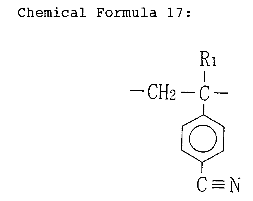 wherein R1 and R2 are the same or different and selected from the group consisting of an alkyl group, a chlorine atom and an alkyl group including a chlorine atom; and R3 is a protecting group released by an acid;
 irradiating said resist film with exposing light of a wavelength of a 1 nm through 30 nm band or a 110 nm through 180 nm band for pattern exposure; andforming a resist pattern by developing said resist film after the pattern exposure.
 - The pattern formation method of Claim 7,
wherein said exposing light is F2 excimer laser, Ar2 excimer laser or soft-X rays. - A pattern formation method comprising the steps of:forming a resist film by applying, on a substrate, a pattern formation material containing a polymer including a first unit represented by Chemical Formula 19, a second unit represented by Chemical Formula 20 and a third unit represented by Chemical Formula 21, and an acid generator;

 wherein R1, R2 and R4 are the same or different and selected from the group consisting of an alkyl group, a chlorine atom and an alkyl group including a chlorine atom; and R3 is a protecting group released by an acid;
 irradiating said resist film with exposing light of a wavelength of a 1 nm through 30 nm band or a 110 nm through 180 nm band for pattern exposure; andforming a resist pattern by developing said resist film after the pattern exposure.
 - The pattern formation method of Claim 9,
wherein said exposing light is F2 excimer laser, Ar2 excimer laser or soft-X rays. - A pattern formation method comprising the steps of:forming a resist film by applying, on a substrate, a pattern formation material containing a polymer including a first unit represented by Chemical Formula 22, a second unit represented by Chemical Formula 23 and a third unit represented by Chemical Formula 24, and an acid generator;

 wherein R1, R2 and R5 are the same or different and selected from the group consisting of an alkyl group, a chlorine atom and an alkyl group including a chlorine atom; and R3 is a protecting group released by an acid;
 irradiating said resist film with exposing light of a wavelength of a 1 nm through 30 nm band or a 110 nm through 180 nm band for pattern exposure; andforming a resist pattern by developing said resist film after the pattern exposure.
 - The pattern formation method of Claim 11,
wherein said exposing light is F2 excimer laser, Ar2 excimer laser or soft-X rays. - A pattern formation method comprising the steps of:forming a resist film by applying, on a substrate, a pattern formation material containing a polymer including a first unit represented by Chemical Formula 25 and a second unit represented by Chemical Formula 26, and an acid generator;
 wherein R1 and R6 are the same or different and selected from the group consisting of an alkyl group, a chlorine atom and an alkyl group including a chlorine atom; and R7 is a protecting group released by an acid;
 irradiating said resist film with exposing light of a wavelength of a 1 nm through 30 nm band or a 110 nm through 180 nm band for pattern exposure; andforming a resist pattern by developing said resist film after the pattern exposure.
 - The pattern formation method of Claim 13,
wherein said exposing light is F2 excimer laser, Ar2 excimer laser or soft-X rays. - A pattern formation method comprising the steps of:forming a resist film by applying, on a substrate, a pattern formation material containing a polymer including a first unit represented by Chemical Formula 27, a second unit represented by Chemical Formula 28 and a third unit represented by Chemical Formula 29, and an acid generator;

 wherein R1, R4 and R6 are the same or different and selected from the group consisting of an alkyl group, a chlorine atom and an alkyl group including a chlorine atom; and R7 is a protecting group released by an acid;
 irradiating said resist film with exposing light of a wavelength of a 1 nm through 30 nm band or a 110 nm through 180 nm band for pattern exposure; andforming a resist pattern by developing said resist film after the pattern exposure.
 - The pattern formation method of Claim 15,
wherein said exposing light is F2 excimer laser, Ar2 excimer laser or soft-X rays. - A pattern formation method comprising the steps of:forming a resist film by applying, on a substrate, a pattern formation material containing a polymer including a first unit represented by Chemical Formula 30, a second unit represented by Chemical Formula 31 and a third unit represented by Chemical Formula 32, and an acid generator;
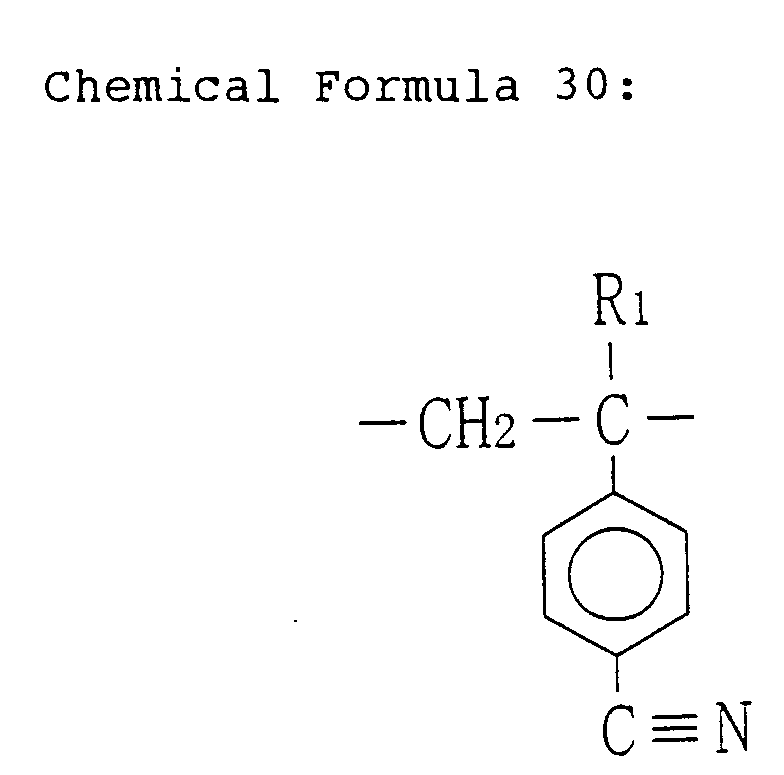
 wherein R1, R5 and R6 are the same or different and selected from the group consisting of an alkyl group, a chlorine atom and an alkyl group including a chlorine atom; and R7 is a protecting group released by an acid;
 irradiating said resist film with exposing light of a wavelength of a 1 nm through 30 nm band or a 110 nm through 180 nm band for pattern exposure; andforming a resist pattern by developing said resist film after the pattern exposure.
 - The pattern formation method of Claim 17,
wherein said exposing light is F2 excimer laser, Ar2 excimer laser or soft-X rays.
Applications Claiming Priority (2)
| Application Number | Priority Date | Filing Date | Title |
|---|---|---|---|
| JP2000071123 | 2000-03-14 | ||
| JP2000071123A JP3437138B2 (en) | 2000-03-14 | 2000-03-14 | Pattern forming material and pattern forming method |
Publications (2)
| Publication Number | Publication Date |
|---|---|
| EP1134617A2 true EP1134617A2 (en) | 2001-09-19 |
| EP1134617A3 EP1134617A3 (en) | 2001-09-26 |
Family
ID=18589749
Family Applications (1)
| Application Number | Title | Priority Date | Filing Date |
|---|---|---|---|
| EP01105830A Withdrawn EP1134617A3 (en) | 2000-03-14 | 2001-03-08 | Pattern formation material and method |
Country Status (5)
| Country | Link |
|---|---|
| US (1) | US6737213B2 (en) |
| EP (1) | EP1134617A3 (en) |
| JP (1) | JP3437138B2 (en) |
| KR (1) | KR100744330B1 (en) |
| TW (1) | TW594409B (en) |
Cited By (1)
| Publication number | Priority date | Publication date | Assignee | Title |
|---|---|---|---|---|
| CN100406481C (en) * | 2003-01-31 | 2008-07-30 | 三菱丽阳株式会社 | Resist polymer and resist composition |
Families Citing this family (1)
| Publication number | Priority date | Publication date | Assignee | Title |
|---|---|---|---|---|
| KR100821440B1 (en) * | 2003-01-31 | 2008-04-10 | 미츠비시 레이온 가부시키가이샤 | Resist polymer and resist composition |
Citations (5)
| Publication number | Priority date | Publication date | Assignee | Title |
|---|---|---|---|---|
| US4996136A (en) * | 1988-02-25 | 1991-02-26 | At&T Bell Laboratories | Radiation sensitive materials and devices made therewith |
| EP0813113A1 (en) * | 1996-06-11 | 1997-12-17 | Shipley Company LLC | Copolymers and photoresist compositions comprising copolymer resin binder component |
| EP0923115A1 (en) * | 1997-12-10 | 1999-06-16 | International Business Machines Corporation | Method for etching a silicon dioxide layer with a fluorocarbon plasma |
| EP0942329A1 (en) * | 1997-09-22 | 1999-09-15 | Clariant International Ltd. | Novel process for preparing resists |
| EP0959389A1 (en) * | 1998-05-19 | 1999-11-24 | JSR Corporation | Diazodisulfone compound and radiation-sensitive resin composition |
Family Cites Families (7)
| Publication number | Priority date | Publication date | Assignee | Title |
|---|---|---|---|---|
| JP3287057B2 (en) | 1993-03-30 | 2002-05-27 | 日本ゼオン株式会社 | Resist composition |
| JPH075682A (en) | 1993-03-30 | 1995-01-10 | Nippon Zeon Co Ltd | Resists composition |
| JPH06289617A (en) | 1993-03-30 | 1994-10-18 | Nippon Zeon Co Ltd | Resist composition |
| US5688628A (en) | 1993-11-11 | 1997-11-18 | Nippon Zeon Co., Ltd. | Resist composition |
| US6004720A (en) * | 1993-12-28 | 1999-12-21 | Fujitsu Limited | Radiation sensitive material and method for forming pattern |
| JP3770694B2 (en) | 1997-04-30 | 2006-04-26 | 富士通株式会社 | Resist material and resist pattern forming method |
| US6303266B1 (en) * | 1998-09-24 | 2001-10-16 | Kabushiki Kaisha Toshiba | Resin useful for resist, resist composition and pattern forming process using the same |
-
2000
- 2000-03-14 JP JP2000071123A patent/JP3437138B2/en not_active Expired - Fee Related
-
2001
- 2001-03-06 US US09/799,017 patent/US6737213B2/en not_active Expired - Lifetime
- 2001-03-07 TW TW090105306A patent/TW594409B/en not_active IP Right Cessation
- 2001-03-08 EP EP01105830A patent/EP1134617A3/en not_active Withdrawn
- 2001-03-14 KR KR1020010013068A patent/KR100744330B1/en not_active IP Right Cessation
Patent Citations (5)
| Publication number | Priority date | Publication date | Assignee | Title |
|---|---|---|---|---|
| US4996136A (en) * | 1988-02-25 | 1991-02-26 | At&T Bell Laboratories | Radiation sensitive materials and devices made therewith |
| EP0813113A1 (en) * | 1996-06-11 | 1997-12-17 | Shipley Company LLC | Copolymers and photoresist compositions comprising copolymer resin binder component |
| EP0942329A1 (en) * | 1997-09-22 | 1999-09-15 | Clariant International Ltd. | Novel process for preparing resists |
| EP0923115A1 (en) * | 1997-12-10 | 1999-06-16 | International Business Machines Corporation | Method for etching a silicon dioxide layer with a fluorocarbon plasma |
| EP0959389A1 (en) * | 1998-05-19 | 1999-11-24 | JSR Corporation | Diazodisulfone compound and radiation-sensitive resin composition |
Cited By (1)
| Publication number | Priority date | Publication date | Assignee | Title |
|---|---|---|---|---|
| CN100406481C (en) * | 2003-01-31 | 2008-07-30 | 三菱丽阳株式会社 | Resist polymer and resist composition |
Also Published As
| Publication number | Publication date |
|---|---|
| KR100744330B1 (en) | 2007-07-30 |
| US20010028989A1 (en) | 2001-10-11 |
| US6737213B2 (en) | 2004-05-18 |
| JP3437138B2 (en) | 2003-08-18 |
| EP1134617A3 (en) | 2001-09-26 |
| TW594409B (en) | 2004-06-21 |
| KR20010092308A (en) | 2001-10-24 |
| JP2001264982A (en) | 2001-09-28 |
Similar Documents
| Publication | Publication Date | Title |
|---|---|---|
| US6632582B2 (en) | Pattern formation material and pattern formation method | |
| US6753132B2 (en) | Pattern formation material and pattern formation method | |
| JP3415799B2 (en) | Resist material and pattern forming method | |
| EP1403711A1 (en) | PATTERN−FORMING MATERIAL AND METHOD OF FORMING PATTERN | |
| US6511786B2 (en) | Pattern formation material and pattern formation method | |
| US6475706B1 (en) | Pattern formation method | |
| US6645694B2 (en) | Pattern formation material and pattern formation method | |
| US6737213B2 (en) | Pattern formation material and method | |
| US6689536B2 (en) | Pattern formation material and pattern formation method | |
| US6576398B2 (en) | Pattern formation material and method | |
| US6830869B2 (en) | Pattern forming material and method of pattern formation | |
| EP1148388A1 (en) | Pattern formation material and pattern formation method | |
| US20030091930A1 (en) | Pattern formation material and pattern formation method | |
| US6806029B2 (en) | Pattern formation material and pattern formation method | |
| JP3299240B2 (en) | Pattern formation method | |
| EP1335246A1 (en) | Pattern formation method | |
| US6537736B1 (en) | Patten formation method |
Legal Events
| Date | Code | Title | Description |
|---|---|---|---|
| PUAI | Public reference made under article 153(3) epc to a published international application that has entered the european phase |
Free format text: ORIGINAL CODE: 0009012 |
|
| PUAL | Search report despatched |
Free format text: ORIGINAL CODE: 0009013 |
|
| AK | Designated contracting states |
Kind code of ref document: A2 Designated state(s): DE FR GB NL Kind code of ref document: A2 Designated state(s): AT BE CH CY DE DK ES FI FR GB GR IE IT LI LU MC NL PT SE TR |
|
| AX | Request for extension of the european patent |
Free format text: AL;LT;LV;MK;RO;SI |
|
| AK | Designated contracting states |
Kind code of ref document: A3 Designated state(s): AT BE CH CY DE DK ES FI FR GB GR IE IT LI LU MC NL PT SE TR |
|
| AX | Request for extension of the european patent |
Free format text: AL;LT;LV;MK;RO;SI |
|
| 17P | Request for examination filed |
Effective date: 20011228 |
|
| AKX | Designation fees paid |
Free format text: DE FR GB NL |
|
| RAP1 | Party data changed (applicant data changed or rights of an application transferred) |
Owner name: PANASONIC CORPORATION |
|
| STAA | Information on the status of an ep patent application or granted ep patent |
Free format text: STATUS: THE APPLICATION HAS BEEN WITHDRAWN |
|
| 18W | Application withdrawn |
Effective date: 20090513 |