EP1134564A2 - Combinational weighing or counting apparatus - Google Patents
Combinational weighing or counting apparatus Download PDFInfo
- Publication number
- EP1134564A2 EP1134564A2 EP01302179A EP01302179A EP1134564A2 EP 1134564 A2 EP1134564 A2 EP 1134564A2 EP 01302179 A EP01302179 A EP 01302179A EP 01302179 A EP01302179 A EP 01302179A EP 1134564 A2 EP1134564 A2 EP 1134564A2
- Authority
- EP
- European Patent Office
- Prior art keywords
- articles
- weighing
- dispensing
- weight
- amount
- Prior art date
- Legal status (The legal status is an assumption and is not a legal conclusion. Google has not performed a legal analysis and makes no representation as to the accuracy of the status listed.)
- Granted
Links
- 238000005303 weighing Methods 0.000 title claims abstract description 113
- 238000001514 detection method Methods 0.000 claims description 18
- 230000032258 transport Effects 0.000 description 20
- 238000011176 pooling Methods 0.000 description 7
- 238000006243 chemical reaction Methods 0.000 description 3
- 230000001276 controlling effect Effects 0.000 description 3
- 230000004043 responsiveness Effects 0.000 description 3
- 238000013459 approach Methods 0.000 description 2
- 230000007423 decrease Effects 0.000 description 2
- 230000000694 effects Effects 0.000 description 2
- 235000009508 confectionery Nutrition 0.000 description 1
- 238000010586 diagram Methods 0.000 description 1
- 235000013399 edible fruits Nutrition 0.000 description 1
- 238000000034 method Methods 0.000 description 1
- 238000004806 packaging method and process Methods 0.000 description 1
- 230000001105 regulatory effect Effects 0.000 description 1
- 238000011144 upstream manufacturing Methods 0.000 description 1
Images



Classifications
-
- G—PHYSICS
- G01—MEASURING; TESTING
- G01G—WEIGHING
- G01G19/00—Weighing apparatus or methods adapted for special purposes not provided for in the preceding groups
- G01G19/40—Weighing apparatus or methods adapted for special purposes not provided for in the preceding groups with provisions for indicating, recording, or computing price or other quantities dependent on the weight
- G01G19/42—Weighing apparatus or methods adapted for special purposes not provided for in the preceding groups with provisions for indicating, recording, or computing price or other quantities dependent on the weight for counting by weighing
-
- G—PHYSICS
- G01—MEASURING; TESTING
- G01G—WEIGHING
- G01G19/00—Weighing apparatus or methods adapted for special purposes not provided for in the preceding groups
- G01G19/387—Weighing apparatus or methods adapted for special purposes not provided for in the preceding groups for combinatorial weighing, i.e. selecting a combination of articles whose total weight or number is closest to a desired value
- G01G19/393—Weighing apparatus or methods adapted for special purposes not provided for in the preceding groups for combinatorial weighing, i.e. selecting a combination of articles whose total weight or number is closest to a desired value using two or more weighing units
Definitions
- This invention generally relates to a combinational weighing or counting apparatus. More specifically, the present invention relates to a combinational weighing or counting apparatus used to weigh with high speed precision articles whose individual weight varies.
- Combinational weighing or counting apparatuses are commonly used to weigh with high speed and precision articles whose individual weight varies, such as sweets or fruits.
- a combinational weighing or counting apparatus includes, for example, a dispensing feeder shaped like a round table, a plurality of radial feeders (discharge troughs) arranged around the dispensing feeder, and a plurality of weighing hoppers arranged below the radial feeders.
- the dispensing feeder and the radial feeders can transport articles by electromagnetically induced vibration.
- the dispensing feeder and the weighing hoppers are each provided with a weighing device (load cell) for measuring the weight of the articles on them.
- a supply device including, for example, a transport conveyor supplies articles to be weighed onto the dispensing feeder
- the dispensing feeder transports the articles by vibration in the radial direction while dispensing them in the circumferential direction, and discharges them onto the radial feeders.
- the radial feeders transport the articles by vibration in the radial direction, and supply them to pooling hoppers.
- the pooling hoppers temporarily store the articles, and then load them into the weighing hoppers.
- a combination control means calculates combinations of the weight of the articles loaded into the weighing hoppers from the weight determined by the weighing devices, and selects weighing hoppers, whose combined weight is within the tolerance range. Then, the selected weighing hoppers are opened, and a predetermined amount of the articles is supplied to the devices downstream.
- the transported amount of articles supplied to the weighing hoppers from the feeders is adjusted by renewing an operating parameter (vibration time and/or amplitude) of each feeder in accordance with the increase or decrease of the desired weight in the weighing hoppers.
- the operating parameters are adjusted such that the weight of the articles in the weighing hoppers approaches the desired weight, and the combined weight approaches the target value.
- the supply/stop of the articles to the dispensing feeder from the supply device is determined depending on the weight of the articles accumulated on the dispensing feeder. More specifically, after a predetermined weight of articles has been supplied, the supply device stops supplying articles. The next supply step starts only after the weight of the articles accumulated on the dispensing feeder has dropped below a predetermined minimum weight.
- the operating parameters (vibration time and/or amplitude) of the dispensing feeder and the radial feeders are feedback-controlled based on the weight in the weighing hoppers.
- the amount of articles supplied to the weighing hoppers is determined mainly by the vibration of the radial feeders, but it is also necessary to control the dispensing feeder so as to suitably supply the articles over the entire transport path. Since the control of the operating parameter of the dispensing feeder is based only on the weight in the weighing hoppers, the following problems occur:
- the dispensing feeder to be controlled is furthest upstream in the transport path and the weighing hoppers serving as the sensors are furthest downstream, the responsiveness with which the transporting of the articles can be controlled at the dispensing portion is low. Therefore, when the desired amount of articles is not transported into the weighing hoppers, it takes a relatively long time_the apparatus to adjust and transport the desired amount of articles into the weighing hoppers
- radial feeders which are controlled separately, are arranged between the dispensing feeder to be controlled and the weighing hoppers serving as the sensors.
- optimum control of the dispensing feeder is difficult. That is to say, when the weight in the weighing hoppers varies, it is sometimes difficult to tell whether the reason for this is the dispensing feeder or one of the radial feeders.
- a combinational weighing or counting apparatus comprises:
- the present invention provides a combinatorial weighing or counting apparatus having a dispensing feeder and weighing hoppers, that achieves superior article transport by suitably controlling the operating parameter of the dispensing feeder.
- articles to be weighed are supplied to the dispensing portion. From the dispensing portion the articles are supplied to the plurality of weighing hoppers.
- the weight detection means detects the weight of the articles on the dispensing portion.
- the control means controls the amount of articles that discharged from the dispensing portion, based on weight information from the weight detection means. With this combinational weighing or counting apparatus, the amount of articles discharged from the dispensing portion is controlled with the weight detection means.
- the weight detection means is provided for the dispensing portion as a sensor, so that the dispensing portion can be controlled suitably.
- control means calculates the amount of articles that is discharged from the dispensing portion using the weight information from the weight detection means.
- the control means controls the amount of articles that is discharged from the dispensing portion, based on this discharge amount.
- the amount of articles discharged from the dispensing portion is controlled based on the amount of articles discharged from the dispensing portion. Therefore, the dispensing portion can be controlled suitably, and superior transport control is possible.
- control means controls the amount of articles that is discharged from the dispensing portion, based on the weight information while the supply of the articles onto the dispensing portion is stopped.
- the weight information is used while the supply of the articles onto the dispensing portion is stopped. Therefore, a precise amount of discharged articles can be obtained. As a result, it becomes possible to control suitably the dispensing portion and superior transport control is possible.
- control means controls the amount of articles that is discharged from the dispensing portion, based on weight information from the weighing hoppers, in addition to the weight information from the weight detection means.
- the weight information from the downstream weighing hoppers can be taken into consideration when controlling the discharge amount from the dispensing feeder. Therefore, it is possible to control suitably the amount of articles discharged from the dispensing feeder in accordance with the transport situation of the articles further downstream.
- the control means controls the amount of articles that is discharged from the dispensing portion, based on weight information from the weight detection means for each weighing cycle.
- "weighing cycle” means not only cycles in the combinational weighing or counting apparatus (loading of articles to be weighed - weighing with the various weighing hoppers - combination calculation - storing of combination weights - discharge), but also includes the cycles per weighing hopper (loading of articles to be weighed - weighing - sending weight to control means - combination calculation - discharge). With this combinational weighing or counting apparatus, the dispensing portion is controlled per cycle period, thereby enabling a finely tuned control adapted to the present state.
- the combinational weighing or counting apparatus further includes a supply device supplies articles to the dispensing portion. Further, the control means controls the supply device based on weight information from the weight detection means. With the combinational weighing or counting apparatus of the present invention, the amount supplied from the supply device is controlled in addition to the suitable control of the dispensing portion. Therefore, the transporting of articles in the dispensing portion can be controlled even further.
- FIG. 1 shows a combinational weighing or counting apparatus 1 in accordance with an embodiment of the present invention.
- This combinational weighing or counting apparatus 1 discharges suitable amounts of articles that are supplied from a supply device 2, for example a feeder or a belt conveyor, into a packaging machine 3. An amount is determined to be suitable by combination weighing.
- the combinational weighing or counting apparatus 1 includes a dispensing feeder 4, a plurality of radial feeders 5 arranged around the dispensing feeder 4, a plurality of pooling hoppers 6 arranged around the radial feeders 5, and a plurality of weighing hoppers 7 arranged underneath the pooling hoppers 6.
- the combinational weighing or counting apparatus 1 further includes a supply chute 8 above the dispensing feeder 4, a collection chute 9 arranged below the weighing hoppers 7, and a discharge chute 10 arranged below the collection chute 9.
- the dispensing feeder 4 includes a table 4a having a substantially cone-shaped upper surface and an electromagnetic vibration unit 4b made of an electromagnetic coil and a spring arranged below the table 4a. More precisely, the table 4a is supported at its base by parallel plate springs, and the base is supported on a ground plane by a plurality of springs.
- the electromagnetic coil of the electromagnetic vibration unit 4b is provided inside the base, and when current is supplied to the electromagnetic coil, it generates a magnetic force, pulling in the table 4a.
- the table 4a descends while turning counterclockwise.
- the restoring force of the plate springs pushes the table 4a back up while turning it clockwise.
- the dispensing feeder 4 is provided with a weighing device (load cell) 11 for measuring the weight of the transported articles on the table 4a.
- the radial feeders 5 include a trough unit 5a and an electromagnetic vibration unit 5b made of an electromagnetic coil and a plate spring, for example, arranged below the trough unit 5a.
- the configuration of the electromagnetic vibration unit 5b is substantially the same as that of the electromagnetic vibration unit 4b of the dispensing feeder 4.
- the weighing hoppers 7 weigh the articles loaded into them from the pooling hoppers 6. Each of the weighing hoppers 7 is provided with a weighing device (load cell) 12. A combination control means (not shown in the drawings) calculates combinations of the weight of the articles in each weighing hopper 7, and selects weighing hoppers 7 whose combined weight is within the tolerance range. Then the discharge gate of the selected weighing hoppers 7 is opened, and articles of a predetermined weight are discharged through the collection chute 9 and the discharge chute 10.
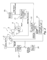
- FIG. 2 is a diagram showing the control system of the combinational weighing or counting apparatus 1 of the present invention.
- This control system mainly includes an RF (radial feeder) operating parameter calculating unit 21, a DF (dispensing-feeder) operating parameter calculating unit 22, and a supply control unit 23.
- the RF operating parameter calculating unit 21 calculates the operating parameter of the radial feeders 5 based on the weight information from the weighing devices 12 and the target weight after combination entered by a remote control 25.
- the DF operating parameter calculating unit 22 calculates the operating parameter of the dispensing feeder 4 based on the weight information from the weighing device 11 and the target weight after combination entered by the remote control 25.
- a discharge amount calculating unit 24 detects the weight from the weighing device 11 for each weighing cycle while the supply of transported articles from the supply device 2 is stopped, and, calculating the difference, passes the amount discharged by the dispensing feeder 4 at each weighing cycle to the DF operating parameter calculating unit 22.
- the supply control unit 23 receives the difference between the weight information from the weighing device 11 and the minimum dispensed amount input by the remote control 25, and turns the supply device 2 on or off depending on this difference.
- the supply device 2 has supplied a predetermined amount of articles to the dispensing feeder 4, it does not supply any more articles until the dispensed amount is lower than the minimum dispensed amount.
- the supply device 2 is alternately in a supply mode and a stopping mode.
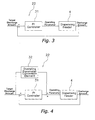
- Figures 3 to 5 illustrate various examples of the feedback control system of the DF operating parameter calculating unit 22.
- Figure 3 shows an example of feedback control only with a PI proportional and integral controller 31.
- the target discharge amount obtained by converting the target weight entered with the remote control 25 and its deviation from the discharge amount serving as the operating parameter are given to the PI controller 31 as the control signals.
- the PI controller 31 then gives a suitable operating parameter to the dispensing feeder 4 to be controlled, such that a discharge amount matching the target value is discharged.
- an operating parameter conversion element 32 which is a function of discharge amount and operating parameter, is added to the operating parameter as a feed-forward element, in addition to the configuration shown in Figure 3.
- the discharge amount is regulated to the vicinity of the target value, so that the PI controller can compensate for discrepancies in relatively small amount of time.
- a fuzzy controller 33 is provided between the PI controller 31 and the dispensing feeder 4, in addition to the configuration shown in Figure 4.
- the fuzzy controller 33 performs fuzzy control on the operating parameter received from the prior stage, and gives the final operating parameter to the dispensing feeder 4. Adding fuzzy control as disclosed in Japanese Patent No. 2683651, the fuzzy controller 33 prevents oversensitiveness due to disturbances.
- the DF operating parameter calculating unit 22 can be realized by fuzzy control PI control or feed-forward control, or by a combination of these.
- the discharge amount calculating unit 24 measures the weight on the dispensing feeder 4 before and after a weighing cycle, and calculates the amount of articles discharged in each cycle from the difference. More specifically, every time the discharge amount calculating unit 24 receives a signal from a combination control unit (not shown in the drawings) that the weighing cycle has been terminated, the discharge amount calculating unit 24 measures and stores the weight on the dispensing feeder 4. Then the discharge amount calculating unit 24 calculates the difference between the current weight and the previous weight, and passes the result of this calculation to the DF operating parameter calculating unit.
- the discharge amount calculating unit 24 compares the discharge amount with a target discharge amount, and supplies the deviation signal to the PI controller 31 shown in Figures 3, 4 and 5.
- the PI controller 31 gives a suitable operating parameter to the dispensing feeder 4 to be controlled, such that a discharge amount matching the target value is discharged.
- the operating parameter given to the dispensing feeder 4 is kept at the operating parameter of the final stage when the supply has been stopped.
- the discharge amount of the weighed articles is controlled on the basis of the amount of weighed articles discharged from the dispensing feeder 4, so that the dispensing feeder can be suitably controlled, and superior transport of the weighed article is possible.
- the following is a description of the specific effects.
- FIG. 6 shows the configuration of the control system of the combinational weighing or counting apparatus 1 in another embodiment.
- the weight value from the weighing devices 12 of the weighing hoppers 7 is supplied to the DF operating parameter calculating unit 22. That is to say, the DF operating parameter calculating unit 22 can control the dispensing feeder 4 under consideration of the weight value from the weighing devices 12 of the weighing hoppers 7 in addition to the weight information from the weighing device 11 of the dispensing feeder 4.
- the weight value from the weighing devices 12 is given into a fuzzy controller 33, and the operating parameter of the dispensing feeder 4 is corrected.
- the weighing values are given directly to the RF operating parameter calculating unit and the DF operating parameter calculating unit in Figures 2 and 6. It is also possible to enter the weighing values into the remote control, and to output them from the remote control to the two operating parameter calculating units.
- the present invention can also be applied to a so-called linear array combinational weighing or counting apparatus, in which the dispensing feeder is changed to the shape of the radial feeders, and a plurality of radial feeders and weighing hoppers are arranged on the discharge side of the dispensing feeder.
- the discharge amount of articles from a dispensing portion is controlled using a weight detection means provided in the dispensing portion.
- the dispensing portion can be controlled suitably, and superior transport of the weighed articles can be attained.
Landscapes
- Physics & Mathematics (AREA)
- General Physics & Mathematics (AREA)
- Engineering & Computer Science (AREA)
- Mathematical Physics (AREA)
- Theoretical Computer Science (AREA)
- Feeding Of Articles To Conveyors (AREA)
- Weight Measurement For Supplying Or Discharging Of Specified Amounts Of Material (AREA)
- Control Of Conveyors (AREA)
Abstract
Description
Claims (6)
- A combinational weighing or counting apparatus comprising:a dispensing portion to which articles to be weighed are supplied;a plurality of weighing hoppers to which the articles are supplied from said dispensing portion;weight detection means to detect the weight of the articles on said dispensing portion; andcontrol means to control an amount of articles discharged from said dispensing portion, based on weight information from said weight detection means.
- A combinational weighing or counting apparatus as set forth in claim 1, wherein
based on the amount discharged, said control means calculates the amount of articles discharged from said dispensing portion using weight information from said weight detection means, and controls the amount of articles discharged from said dispensing portion. - A combinational weighing or counting apparatus according to claim 1 or claim 2, wherein
said control means controls the amount of articles discharged from said dispensing portion, based on said weight information from said weight detection means while a supply of articles onto said dispensing portion is stopped. - A combinational weighing or counting apparatus according to any of claims 1 to 3, wherein
said control means controls the amount of articles discharged from said dispensing portion, based on weight information from said weighing hoppers, in addition to said weight information from said weight detection means. - A combinational weighing or counting apparatus according to any of the preceding claims, wherein
said control means controls the amount of articles discharged from said dispensing portion, based on said weight information from said weight detection means for each weighing cycle. - A combinational weighing or counting apparatus according to any of the preceding claims, further comprising a supply device supplying the articles to said dispensing portion,
wherein said control means controls said supply device, based on weight information from said weight detection means.
Applications Claiming Priority (2)
| Application Number | Priority Date | Filing Date | Title |
|---|---|---|---|
| JP2000067931A JP2001255198A (en) | 2000-03-13 | 2000-03-13 | Combination weighing counter |
| JP2000067931 | 2000-03-13 |
Publications (3)
| Publication Number | Publication Date |
|---|---|
| EP1134564A2 true EP1134564A2 (en) | 2001-09-19 |
| EP1134564A3 EP1134564A3 (en) | 2002-06-05 |
| EP1134564B1 EP1134564B1 (en) | 2007-01-03 |
Family
ID=18587051
Family Applications (1)
| Application Number | Title | Priority Date | Filing Date |
|---|---|---|---|
| EP01302179A Revoked EP1134564B1 (en) | 2000-03-13 | 2001-03-09 | Combinational weighing or counting apparatus |
Country Status (4)
| Country | Link |
|---|---|
| US (1) | US6545230B2 (en) |
| EP (1) | EP1134564B1 (en) |
| JP (1) | JP2001255198A (en) |
| DE (1) | DE60125623T2 (en) |
Cited By (3)
| Publication number | Priority date | Publication date | Assignee | Title |
|---|---|---|---|---|
| EP1420232A2 (en) | 2002-11-14 | 2004-05-19 | Ishida Co., Ltd. | Combinational weighing device |
| EP1424542A1 (en) * | 2002-11-29 | 2004-06-02 | Ishida Co., Ltd. | Combination weighing device |
| EP2063237A1 (en) | 2007-11-26 | 2009-05-27 | TNA Australia Pty Limited | A scale for a packaging machine |
Families Citing this family (17)
| Publication number | Priority date | Publication date | Assignee | Title |
|---|---|---|---|---|
| US7075018B1 (en) * | 1998-12-09 | 2006-07-11 | Temafa Maschinenfabrik Gmbh | Mixing fibrous constituents |
| ITPD20020239A1 (en) * | 2002-09-20 | 2004-03-21 | Martini Srl | POWER SUPPLY AND SIGNAL DISTRIBUTOR |
| US20060162970A1 (en) * | 2003-07-17 | 2006-07-27 | Petur Gudjonsson | Method and a system for batching items into receptacles |
| FR2874211B1 (en) * | 2004-08-10 | 2006-10-20 | Movidis Sa | DEVICE FOR TRANSFERRING AND DOSING PULVERULENT OR GRANULAR MATERIAL CONTAINED IN A HOPPER |
| US20070232885A1 (en) * | 2006-03-03 | 2007-10-04 | Thomas Cook | Medical imaging examination review and quality assurance system and method |
| US20120192530A1 (en) * | 2009-06-18 | 2012-08-02 | Schmidt Rogerio | Dosage system of solid products for packing machines |
| US9533775B1 (en) * | 2009-09-30 | 2017-01-03 | Matrix Packaging Machinery Llc | Particle packaging systems and associated methods |
| WO2012098592A1 (en) * | 2011-01-20 | 2012-07-26 | 大和製衡株式会社 | Weighing device |
| US9194735B2 (en) * | 2012-03-16 | 2015-11-24 | Ishida Co., Ltd. | Combination weighing device initialization |
| CN108463698B (en) * | 2016-01-14 | 2020-09-25 | 株式会社石田 | Control device for combined metering device, combined metering device and system thereof |
| JP6676503B2 (en) * | 2016-09-07 | 2020-04-08 | 大和製衡株式会社 | Combination scale |
| US11137280B2 (en) * | 2017-04-28 | 2021-10-05 | Shozo Kawanishi | Weighing apparatus including rough-charge weigher and combination weigher |
| CN108268930B (en) * | 2018-01-31 | 2022-02-01 | 华北理工大学 | Bar weighing counter and weighing counting method |
| JP7081795B2 (en) * | 2018-03-26 | 2022-06-07 | 株式会社イシダ | Transport device and combination weighing device |
| CN111559543A (en) * | 2019-02-13 | 2020-08-21 | 株式会社石田 | Metering and packaging system |
| JP7323921B2 (en) * | 2019-09-12 | 2023-08-09 | 株式会社イシダ | Combination weighing device |
| CN115027758B (en) * | 2022-02-17 | 2023-07-18 | 南通恒力包装科技股份有限公司 | Counting and weighing device |
Family Cites Families (14)
| Publication number | Priority date | Publication date | Assignee | Title |
|---|---|---|---|---|
| GB1449482A (en) | 1973-07-17 | 1976-09-15 | Hobart Eng Ltd | Feed control system |
| GB2100449B (en) * | 1981-06-17 | 1985-05-22 | Yamato Scale Co Ltd | Combination weighing machine |
| JPS60134128U (en) * | 1984-02-16 | 1985-09-06 | 株式会社 石田衡器製作所 | Weighing device |
| US4708215A (en) * | 1984-08-08 | 1987-11-24 | Ishida Scales Manufacturing Company, Ltd. | Automatic weighing system |
| JP2683651B2 (en) * | 1987-11-12 | 1997-12-03 | 株式会社イシダ | Supply control device for distributed feeder |
| US5074436A (en) * | 1989-07-10 | 1991-12-24 | Yamato Scale Company, Limited | Product feeding device for combination weigher |
| JPH05201521A (en) * | 1992-01-23 | 1993-08-10 | Anritsu Corp | Distribution supply apparatus |
| JP3112331B2 (en) * | 1992-03-11 | 2000-11-27 | 大和製衡株式会社 | Control device of dispersion feeder in combination weigher |
| EP0576223B1 (en) * | 1992-06-26 | 1997-08-20 | ISHIDA CO., Ltd. | Combinational weighing machine with special feeder control |
| JP3305816B2 (en) * | 1992-06-26 | 2002-07-24 | 株式会社イシダ | Combination weighing device |
| JPH07311077A (en) * | 1994-05-16 | 1995-11-28 | Ishida Co Ltd | Combination weighing system |
| JPH08178734A (en) * | 1994-12-20 | 1996-07-12 | Ishida Co Ltd | Combination weighing device |
| GB2302950B (en) * | 1995-07-01 | 1999-03-10 | Ward Bekker Systems Limited | Material feed apparatus |
| JPH09329484A (en) | 1996-06-10 | 1997-12-22 | Anritsu Corp | Combination measuring system |
-
2000
- 2000-03-13 JP JP2000067931A patent/JP2001255198A/en active Pending
-
2001
- 2001-03-09 EP EP01302179A patent/EP1134564B1/en not_active Revoked
- 2001-03-09 DE DE60125623T patent/DE60125623T2/en not_active Expired - Fee Related
- 2001-03-09 US US09/801,809 patent/US6545230B2/en not_active Expired - Fee Related
Cited By (7)
| Publication number | Priority date | Publication date | Assignee | Title |
|---|---|---|---|---|
| EP1420232A2 (en) | 2002-11-14 | 2004-05-19 | Ishida Co., Ltd. | Combinational weighing device |
| EP1420232A3 (en) * | 2002-11-14 | 2006-12-20 | Ishida Co., Ltd. | Combinational weighing device |
| EP2386839A1 (en) * | 2002-11-14 | 2011-11-16 | ISHIDA CO., Ltd. | Combinational weighing device |
| EP1424542A1 (en) * | 2002-11-29 | 2004-06-02 | Ishida Co., Ltd. | Combination weighing device |
| US7064281B2 (en) | 2002-11-29 | 2006-06-20 | Ishida Co., Ltd. | Combination weighing device |
| EP2063237A1 (en) | 2007-11-26 | 2009-05-27 | TNA Australia Pty Limited | A scale for a packaging machine |
| AU2008221530B2 (en) * | 2007-11-26 | 2010-07-01 | Tna Australia Pty Limited | A scale for a packaging machine |
Also Published As
| Publication number | Publication date |
|---|---|
| EP1134564A3 (en) | 2002-06-05 |
| EP1134564B1 (en) | 2007-01-03 |
| DE60125623D1 (en) | 2007-02-15 |
| JP2001255198A (en) | 2001-09-21 |
| DE60125623T2 (en) | 2007-10-11 |
| US6545230B2 (en) | 2003-04-08 |
| US20010020553A1 (en) | 2001-09-13 |
Similar Documents
| Publication | Publication Date | Title |
|---|---|---|
| EP1134564B1 (en) | Combinational weighing or counting apparatus | |
| CA2172310C (en) | Apparatus and method for controlling a vibratory feeder in a weighing machine | |
| US6376784B1 (en) | Vibrating transport apparatus and method of detecting vibration characteristic | |
| AU2016216986B2 (en) | Conveyor apparatus and combined weighing apparatus | |
| JPWO1995031702A1 (en) | Combination weighing device | |
| US4129189A (en) | Weight control system | |
| US5756939A (en) | Combinational weighing machine | |
| US4574849A (en) | Apparatus and method for controlling supply of articles | |
| EP0650038B1 (en) | Bucket lift distribution system | |
| EP4529611B1 (en) | Methods of identifying defective dispersion feeders | |
| JP5762865B2 (en) | Combination scale | |
| JPH01148916A (en) | Quantitative weighing apparatus | |
| JP2002062185A (en) | Combination weighing device | |
| JP2000275090A (en) | Method and apparatus for weighing goods | |
| US20110168455A1 (en) | Weighing apparatus and method | |
| CN114441013A (en) | Combined metering device | |
| JPH07311077A (en) | Combination weighing system | |
| JP2003083797A (en) | Management method of belt conveyor conveyance amount | |
| WO2025179696A1 (en) | Material level measurement method, material level measurement control device, and asphalt mixing plant | |
| SU1516792A1 (en) | Method of weighing loose materials and weigher for loose materials | |
| CN2062440U (en) | Speed-adjustable quantitative feeding belt scale | |
| JPH06198252A (en) | Multistep weight classifying apparatus | |
| WO2025070671A1 (en) | Transport device, and weighing and serving system | |
| SU1048327A1 (en) | Loose material batcher | |
| JPH05180687A (en) | Combination metering device |
Legal Events
| Date | Code | Title | Description |
|---|---|---|---|
| PUAI | Public reference made under article 153(3) epc to a published international application that has entered the european phase |
Free format text: ORIGINAL CODE: 0009012 |
|
| AK | Designated contracting states |
Kind code of ref document: A2 Designated state(s): AT BE CH CY DE DK ES FI FR GB GR IE IT LI LU MC NL PT SE TR |
|
| AX | Request for extension of the european patent |
Free format text: AL;LT;LV;MK;RO;SI |
|
| PUAL | Search report despatched |
Free format text: ORIGINAL CODE: 0009013 |
|
| AK | Designated contracting states |
Kind code of ref document: A3 Designated state(s): AT BE CH CY DE DK ES FI FR GB GR IE IT LI LU MC NL PT SE TR |
|
| AX | Request for extension of the european patent |
Free format text: AL;LT;LV;MK;RO;SI |
|
| 17P | Request for examination filed |
Effective date: 20021112 |
|
| AKX | Designation fees paid |
Designated state(s): DE FR GB IT |
|
| GRAP | Despatch of communication of intention to grant a patent |
Free format text: ORIGINAL CODE: EPIDOSNIGR1 |
|
| GRAC | Information related to communication of intention to grant a patent modified |
Free format text: ORIGINAL CODE: EPIDOSCIGR1 |
|
| GRAS | Grant fee paid |
Free format text: ORIGINAL CODE: EPIDOSNIGR3 |
|
| GRAA | (expected) grant |
Free format text: ORIGINAL CODE: 0009210 |
|
| AK | Designated contracting states |
Kind code of ref document: B1 Designated state(s): DE FR GB IT |
|
| REG | Reference to a national code |
Ref country code: GB Ref legal event code: FG4D |
|
| REF | Corresponds to: |
Ref document number: 60125623 Country of ref document: DE Date of ref document: 20070215 Kind code of ref document: P |
|
| ET | Fr: translation filed | ||
| PLAZ | Examination of admissibility of opposition: despatch of communication + time limit |
Free format text: ORIGINAL CODE: EPIDOSNOPE2 |
|
| PLBI | Opposition filed |
Free format text: ORIGINAL CODE: 0009260 |
|
| PLAX | Notice of opposition and request to file observation + time limit sent |
Free format text: ORIGINAL CODE: EPIDOSNOBS2 |
|
| PLBA | Examination of admissibility of opposition: reply received |
Free format text: ORIGINAL CODE: EPIDOSNOPE4 |
|
| 26 | Opposition filed |
Opponent name: MULTIPOND WAEGETECHNIK GMBH Effective date: 20071004 |
|
| PLAF | Information modified related to communication of a notice of opposition and request to file observations + time limit |
Free format text: ORIGINAL CODE: EPIDOSCOBS2 |
|
| PLBB | Reply of patent proprietor to notice(s) of opposition received |
Free format text: ORIGINAL CODE: EPIDOSNOBS3 |
|
| PGFP | Annual fee paid to national office [announced via postgrant information from national office to epo] |
Ref country code: GB Payment date: 20090304 Year of fee payment: 9 |
|
| RDAF | Communication despatched that patent is revoked |
Free format text: ORIGINAL CODE: EPIDOSNREV1 |
|
| PGFP | Annual fee paid to national office [announced via postgrant information from national office to epo] |
Ref country code: DE Payment date: 20090306 Year of fee payment: 9 Ref country code: IT Payment date: 20090317 Year of fee payment: 9 |
|
| PGFP | Annual fee paid to national office [announced via postgrant information from national office to epo] |
Ref country code: FR Payment date: 20090316 Year of fee payment: 9 |
|
| GBPC | Gb: european patent ceased through non-payment of renewal fee |
Effective date: 20100309 |
|
| REG | Reference to a national code |
Ref country code: FR Ref legal event code: ST Effective date: 20101130 |
|
| PG25 | Lapsed in a contracting state [announced via postgrant information from national office to epo] |
Ref country code: FR Free format text: LAPSE BECAUSE OF NON-PAYMENT OF DUE FEES Effective date: 20100331 |
|
| PG25 | Lapsed in a contracting state [announced via postgrant information from national office to epo] |
Ref country code: DE Free format text: LAPSE BECAUSE OF NON-PAYMENT OF DUE FEES Effective date: 20101001 |
|
| RDAG | Patent revoked |
Free format text: ORIGINAL CODE: 0009271 |
|
| STAA | Information on the status of an ep patent application or granted ep patent |
Free format text: STATUS: PATENT REVOKED |
|
| PG25 | Lapsed in a contracting state [announced via postgrant information from national office to epo] |
Ref country code: GB Free format text: LAPSE BECAUSE OF NON-PAYMENT OF DUE FEES Effective date: 20100309 Ref country code: IT Free format text: LAPSE BECAUSE OF NON-PAYMENT OF DUE FEES Effective date: 20100309 |
|
| 27W | Patent revoked |
Effective date: 20090802 |