EP1134563A2 - Ölfüllstandssensor - Google Patents
Ölfüllstandssensor Download PDFInfo
- Publication number
- EP1134563A2 EP1134563A2 EP01100860A EP01100860A EP1134563A2 EP 1134563 A2 EP1134563 A2 EP 1134563A2 EP 01100860 A EP01100860 A EP 01100860A EP 01100860 A EP01100860 A EP 01100860A EP 1134563 A2 EP1134563 A2 EP 1134563A2
- Authority
- EP
- European Patent Office
- Prior art keywords
- oil level
- oil
- sensor
- level sensor
- sensor according
- Prior art date
- Legal status (The legal status is an assumption and is not a legal conclusion. Google has not performed a legal analysis and makes no representation as to the accuracy of the status listed.)
- Granted
Links
Images
Classifications
-
- G—PHYSICS
- G01—MEASURING; TESTING
- G01F—MEASURING VOLUME, VOLUME FLOW, MASS FLOW OR LIQUID LEVEL; METERING BY VOLUME
- G01F23/00—Indicating or measuring liquid level or level of fluent solid material, e.g. indicating in terms of volume or indicating by means of an alarm
- G01F23/22—Indicating or measuring liquid level or level of fluent solid material, e.g. indicating in terms of volume or indicating by means of an alarm by measuring physical variables, other than linear dimensions, pressure or weight, dependent on the level to be measured, e.g. by difference of heat transfer of steam or water
- G01F23/24—Indicating or measuring liquid level or level of fluent solid material, e.g. indicating in terms of volume or indicating by means of an alarm by measuring physical variables, other than linear dimensions, pressure or weight, dependent on the level to be measured, e.g. by difference of heat transfer of steam or water by measuring variations of resistance of resistors due to contact with conductor fluid
- G01F23/246—Indicating or measuring liquid level or level of fluent solid material, e.g. indicating in terms of volume or indicating by means of an alarm by measuring physical variables, other than linear dimensions, pressure or weight, dependent on the level to be measured, e.g. by difference of heat transfer of steam or water by measuring variations of resistance of resistors due to contact with conductor fluid thermal devices
- G01F23/247—Indicating or measuring liquid level or level of fluent solid material, e.g. indicating in terms of volume or indicating by means of an alarm by measuring physical variables, other than linear dimensions, pressure or weight, dependent on the level to be measured, e.g. by difference of heat transfer of steam or water by measuring variations of resistance of resistors due to contact with conductor fluid thermal devices for discrete levels
- G01F23/248—Constructional details; Mounting of probes
-
- F—MECHANICAL ENGINEERING; LIGHTING; HEATING; WEAPONS; BLASTING
- F01—MACHINES OR ENGINES IN GENERAL; ENGINE PLANTS IN GENERAL; STEAM ENGINES
- F01M—LUBRICATING OF MACHINES OR ENGINES IN GENERAL; LUBRICATING INTERNAL COMBUSTION ENGINES; CRANKCASE VENTILATING
- F01M11/00—Component parts, details or accessories, not provided for in, or of interest apart from, groups F01M1/00 - F01M9/00
- F01M11/10—Indicating devices; Other safety devices
- F01M11/12—Indicating devices; Other safety devices concerning lubricant level
-
- G—PHYSICS
- G01—MEASURING; TESTING
- G01F—MEASURING VOLUME, VOLUME FLOW, MASS FLOW OR LIQUID LEVEL; METERING BY VOLUME
- G01F23/00—Indicating or measuring liquid level or level of fluent solid material, e.g. indicating in terms of volume or indicating by means of an alarm
- G01F23/22—Indicating or measuring liquid level or level of fluent solid material, e.g. indicating in terms of volume or indicating by means of an alarm by measuring physical variables, other than linear dimensions, pressure or weight, dependent on the level to be measured, e.g. by difference of heat transfer of steam or water
- G01F23/26—Indicating or measuring liquid level or level of fluent solid material, e.g. indicating in terms of volume or indicating by means of an alarm by measuring physical variables, other than linear dimensions, pressure or weight, dependent on the level to be measured, e.g. by difference of heat transfer of steam or water by measuring variations of capacity or inductance of capacitors or inductors arising from the presence of liquid or fluent solid material in the electric or electromagnetic fields
- G01F23/263—Indicating or measuring liquid level or level of fluent solid material, e.g. indicating in terms of volume or indicating by means of an alarm by measuring physical variables, other than linear dimensions, pressure or weight, dependent on the level to be measured, e.g. by difference of heat transfer of steam or water by measuring variations of capacity or inductance of capacitors or inductors arising from the presence of liquid or fluent solid material in the electric or electromagnetic fields by measuring variations in capacitance of capacitors
- G01F23/268—Indicating or measuring liquid level or level of fluent solid material, e.g. indicating in terms of volume or indicating by means of an alarm by measuring physical variables, other than linear dimensions, pressure or weight, dependent on the level to be measured, e.g. by difference of heat transfer of steam or water by measuring variations of capacity or inductance of capacitors or inductors arising from the presence of liquid or fluent solid material in the electric or electromagnetic fields by measuring variations in capacitance of capacitors mounting arrangements of probes
Definitions
- the invention relates to an oil level sensor according to the generic term of claim 1.
- the invention is therefore based on the object of reliable oil level measurement at all times to be able to make, even if the vehicle to cross and / or Longitudinal axis is inclined.
- the senor Because the sensor is constantly flowed through by oil, it can become in the measuring section the sensor does not form a deposit that prevents the oil from entering or leaving, so that a reliable measurement of the oil level can always take place. A cleaning of the Sensor is therefore unnecessary.
- the suction tube is arranged in the vicinity of the neutral fiber, or that it follows the neutral fiber in its course can be a reliable oil measurement even if the vehicle is inclined to either side.
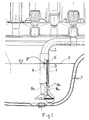
- the sensor 1 of the oil level sensor is in the example shown in Fig. 1 as capacitive Sensor trained. According to the invention, this sensor 1 is in a suction pipe 2 the circulation lubrication integrated so that it is constantly flowed through by the oil and so contamination or even clogging is reliably avoided.
- the sensor 1 consists of an outer electrode 3 and an inner electrode 4 arranged concentrically therewith. Between the cylindrical electrodes 3, 4 there is an annular space 5 through which the oil flows.
- the suction pipe 2 can also be designed as an outer electrode 3. If the outer electrode 3 and inner electrode 4 are made of plastic, it is necessary to provide the mutually opposing surfaces with a conductive layer which is connected via leads 8a, 8b to the coil of a resonant circuit, not shown here.
- the oil forms a dielectric.
- the oil level sensor 1 can be connected in parallel with a coil, so that a resonant circuit is created. Small changes in the mirror 6 lead to a detuning of the resonant circuit by changing the capacitance of the sensor 1 and indicate in an electronic system that oil must be topped up.
- Point 7 is the intersection of mirror 6 with the neutral fiber.
- suction pipe 2 is not as is straight in the example shown, but is curved such that it The course of the neutral fiber follows.
- the neutral fiber is defined so that it has that space curve within an irregular one shaped hollow body describes, which is the same from the respective points Surface height with constant filling volume regardless of the room inclination (within certain limits).
- the sensor 1 can also be designed as an inductive sensor.
- the coil is then ins Suction pipe 2 installed and the oil flows through the core of the coil.
- the inductance of the Coil is a function of mirror 6.
- the coil is connected in parallel with a capacitance and in turn forms a resonant circuit.
- sensors can also be used which work according to the known system of the hot wire, its resistance changes with temperature. This change in temperature is a function the oil level in the oil pan.
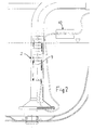
- the oil level in the intake manifold 2 with temperature-dependent PTC or NTC resistors 9 are measured. These resistors 9 are at intervals arranged one above the other in the intake manifold 2 and individually with an external electronic Evaluation circuit 10 connected. According to the invention, the result of the evaluation Reliable, because of the arrangement in the intake manifold 2, the entire measuring section always from Engine oil flows through and is kept free of sediments.
- a temperature measuring pill can also be placed in the oil level sensor to record the oil temperature be integrated.
- the oil level probe according to the invention is always ready for measurement since there is no contamination can arise and since they are independent of changes in position of the internal combustion engine is. The construction effort is very low.
Landscapes
- Physics & Mathematics (AREA)
- Engineering & Computer Science (AREA)
- Thermal Sciences (AREA)
- Fluid Mechanics (AREA)
- General Physics & Mathematics (AREA)
- Power Engineering (AREA)
- Mechanical Engineering (AREA)
- General Engineering & Computer Science (AREA)
- Electromagnetism (AREA)
- Lubrication Details And Ventilation Of Internal Combustion Engines (AREA)
- Measurement Of Levels Of Liquids Or Fluent Solid Materials (AREA)
Abstract
Description
- Fig. 1
- einen Schnitt durch einen Sensor im Saugrohr einer Umlaufschmierung
- Fig. 2
- einen Schnitt durch das Saugrohr mit Sensor in Form von Einzelwiderständen
Das Öl bildet ein Dielektrikum. Im Stillstand der Brennkraftmaschine, wenn kein Öl umgewälzt wird, befindet sich der Ölstand im Ringraum 5 nach dem Prinzip kommunizierender Rohre auf dem gleichen Niveau wie der Spiegel 6 der Ölwanne 7. Die Höhe des Spiegels 6 beeinflußt die Kapazität des Sensors 1. Der Ölstandssensor 1 kann mit einer Spule parallel geschaltet werden, so daß ein Schwingkreis entsteht. Geringe Änderungen des Spiegels 6 führen durch Veränderung der Kapazität des Sensors 1 zu einer Verstimmung des Schwingkreises und zeigen in einer Elektronik an, daß Öl nachzufüllen ist.
Claims (10)
- Ölfüllstandssensor, bestehend aus einem Sensor und einer Elektronik zur Auswertung des durch den Sensor gemessenen Ölstandes, dadurch gekennzeichnet, daß der Sensor (1) in ein Saugrohr (2) der Umlaufschmierung einer Brennkraftmaschine integriert ist, derart, daß das Öl ständig die Meßstrecke des Sensors (1) durchströmt.
- Ölfüllstandssensor nach Anspruch 1, dadurch gekennzeichnet, daß das Saugrohr (2) in der Umgebung einer neutralen Faser in einer Ölwanne (7) angeordnet ist.
- Ölfüllstandssensor nach Anspruch 1, dadurch gekennzeichnet, daß das Saugrohr (2) selbst eine Krümmung aufweist, welche der neutralen Faser folgt.
- Ölfüllstandssensor nach den Ansprüchen 1 bis 3, dadurch gekennzeichnet, daß der Sensor (1) als kapazitiver Sensor ausgebildet ist, welcher aus zwei zueinander konzentrischen äußeren und inneren Elektroden ( 3, 4) besteht und daß das Öl der Umlaufschmierung einen Ringraum (5) zwischen den Elektroden (3,4) durchflutet.
- Ölfüllstandssensor nach den Ansprüchen 1 bis 4, dadurch gekennzeichnet, daß das Saugrohr (2) die äußere Elektrode (3) des Sensors (1) bildet, wobei das Saugrohr in Kunststoff gefertigt ist, daß die innere Elektrode (4) ebenfalls in Kunststoff gefertigt ist, daß die sich gegenüberstehenden Oberflächen der Elektroden ( 3 und 4 ) mit einem leitfähigen Belag beschichtet sind und daß die Elektroden (3, 4 ) über Zuleitungen (8a, 8b) mit einem Schwingkreis der Elektronik verbunden sind.
- Ölfüllstandssensor nach den Ansprüchen 1 bis 3, dadurch gekennzeichnet, daß der Sensor (1) als induktiver Sensor ausgebildet ist, daß die Induktivität als Spule ausgebildet ist welche im Saugrohr (2) angeordnet ist und daß die Seele der Spule vom Motoröl durchströmt wird.
- Ölfüllstandssensor nach den Ansprüchen 1 bis 3, dadurch gekennzeichnet, daß der Sensor (1) thermisch nach dem Prinzip des Hitzdrahtes arbeitet.
- Ölfüllstandssensor nach Anspruch 7, dadurch gekennzeichnet, daß an Stelle des Hitzdrahtes PTC- oder NTC Widerstände verwendet werden und daß diese Widerstände im Saugrohr (2) geometrisch gesehen übereinander angeordnet werden.
- Ölfüllstandssensor nach den Ansprüchen 1 bis 6, dadurch gekennzeichnet, daß die Auswertung der Meßergebnisse der Sensoren (1) mittels eines abgestimmten Schwingkreises erfolgt.
- Ölfüllstandssensor nach den Anspruch 7 und 8, dadurch gekennzeichnet, daß die Auswertung der Meßergebnisse in einer elektronischen Auswerteschaltung erfolgt.
Applications Claiming Priority (2)
| Application Number | Priority Date | Filing Date | Title |
|---|---|---|---|
| DE2000111860 DE10011860B4 (de) | 2000-03-10 | 2000-03-10 | Ölfüllstandssensor |
| DE10011860 | 2000-03-10 |
Publications (3)
| Publication Number | Publication Date |
|---|---|
| EP1134563A2 true EP1134563A2 (de) | 2001-09-19 |
| EP1134563A3 EP1134563A3 (de) | 2007-08-22 |
| EP1134563B1 EP1134563B1 (de) | 2008-12-31 |
Family
ID=7634323
Family Applications (1)
| Application Number | Title | Priority Date | Filing Date |
|---|---|---|---|
| EP20010100860 Expired - Lifetime EP1134563B1 (de) | 2000-03-10 | 2001-01-16 | Ölfüllstandssensor |
Country Status (2)
| Country | Link |
|---|---|
| EP (1) | EP1134563B1 (de) |
| DE (2) | DE10011860B4 (de) |
Cited By (3)
| Publication number | Priority date | Publication date | Assignee | Title |
|---|---|---|---|---|
| CN107725143A (zh) * | 2016-08-11 | 2018-02-23 | 赛峰航空助推器股份有限公司 | 用于涡轮机的具有水平测量的机油箱体 |
| EP4312002A3 (de) * | 2022-07-07 | 2024-05-15 | Herbert Saier GmbH | Sauglanze |
| RU234623U1 (ru) * | 2024-12-11 | 2025-06-03 | федеральное государственное автономное образовательное учреждение высшего образования "Национальный исследовательский ядерный университет МИФИ" (НИЯУ МИФИ) | Устройство контроля моторного масла в двигателе внутреннего сгорания |
Families Citing this family (5)
| Publication number | Priority date | Publication date | Assignee | Title |
|---|---|---|---|---|
| DE10250523B4 (de) * | 2001-10-31 | 2008-12-11 | Ifm Electronic Gmbh | Verfahren zur Erfassung der Kapazität bzw. einer Kapazitätsänderung eines kapazitiven Schaltungs- oder Bauelementes |
| DE10153298C5 (de) * | 2001-10-31 | 2012-05-03 | Ifm Electronic Gmbh | Verfahren zur Erfassung der Kapazität bzw. einer Kapazitäts-Änderung eines kapazitiven Schaltungs- oder Bauelementes |
| FR2922591A1 (fr) * | 2007-10-19 | 2009-04-24 | Renault Sas | Tuyau d'aspiration de liquide comprenant un moyen de jaugeage |
| DE102008031645B4 (de) * | 2008-07-04 | 2018-10-18 | Continental Automotive Gmbh | Füllstandssensor und Verfahren zur Sensierung des Füllstands eines Tanks |
| US9771840B2 (en) | 2015-02-24 | 2017-09-26 | GM Global Technology Operations LLC | Oil pan and engine assembly including the oil pan |
Family Cites Families (7)
| Publication number | Priority date | Publication date | Assignee | Title |
|---|---|---|---|---|
| US5001927A (en) * | 1989-09-25 | 1991-03-26 | Teleflex Incorporated | Full sensing unit |
| DE9218364U1 (de) * | 1992-09-02 | 1994-01-27 | Doduco GmbH + Co Dr. Eugen Dürrwächter, 75181 Pforzheim | Vorrichtung zur Messung des Ölstands |
| DE4327262C1 (de) * | 1993-08-13 | 1994-10-20 | Daimler Benz Ag | Schmierölkreislauf für eine Brennkraftmaschine mit einer ventilgesteuerten Nachfülleinrichtung |
| DE29606311U1 (de) * | 1996-03-29 | 1997-07-24 | Willy Vogel AG, 12277 Berlin | Vorrichtung zur Ölstandsüberwachung bei einer Verbrennungskraftmaschine |
| DE19735374C2 (de) * | 1997-08-14 | 2001-09-13 | Siemens Ag | Vorrichtung zur Messung des Ölstandes, insbesondere zur Messung des Ölstandes in der Ölwanne von Kraftfahrzeug-Verbrennungsmotoren |
| DE19834387A1 (de) * | 1998-07-30 | 2000-02-03 | Intermodul Gmbh | Schmierölsystem mit Ölniveauregelung für eine Brennkraftmaschine mit Ölumlauf zwischen Ölwanne und Ölvorratsbehälter |
| DE19859337A1 (de) * | 1998-12-22 | 2000-07-06 | Mannesmann Vdo Ag | Verfahren zur Überwachung der ausreichenden Ölschmierung eines Verbrennungsmotors und Verbrennungsmotor zur Durchführung des Verfahrens |
-
2000
- 2000-03-10 DE DE2000111860 patent/DE10011860B4/de not_active Expired - Fee Related
-
2001
- 2001-01-16 EP EP20010100860 patent/EP1134563B1/de not_active Expired - Lifetime
- 2001-01-16 DE DE50114607T patent/DE50114607D1/de not_active Expired - Fee Related
Cited By (3)
| Publication number | Priority date | Publication date | Assignee | Title |
|---|---|---|---|---|
| CN107725143A (zh) * | 2016-08-11 | 2018-02-23 | 赛峰航空助推器股份有限公司 | 用于涡轮机的具有水平测量的机油箱体 |
| EP4312002A3 (de) * | 2022-07-07 | 2024-05-15 | Herbert Saier GmbH | Sauglanze |
| RU234623U1 (ru) * | 2024-12-11 | 2025-06-03 | федеральное государственное автономное образовательное учреждение высшего образования "Национальный исследовательский ядерный университет МИФИ" (НИЯУ МИФИ) | Устройство контроля моторного масла в двигателе внутреннего сгорания |
Also Published As
| Publication number | Publication date |
|---|---|
| EP1134563B1 (de) | 2008-12-31 |
| EP1134563A3 (de) | 2007-08-22 |
| DE50114607D1 (de) | 2009-02-12 |
| DE10011860A1 (de) | 2001-09-27 |
| DE10011860B4 (de) | 2008-03-13 |
Similar Documents
| Publication | Publication Date | Title |
|---|---|---|
| DE19511556C1 (de) | Sensoranordnung | |
| EP1792170B1 (de) | Sensorelement für partikelsensoren und verfahren zum betrieb desselben | |
| DE69228548T2 (de) | Digitales füllstands-messsondensystem | |
| EP0926475A2 (de) | Kapazitiver Füllstandssensor mit integrierter Schmutzfilmdetektion | |
| DE112011101496T5 (de) | Mehrleiter-Wasser-in-Kraftstoff-Sensor für Füllgeschwindigkeiterkennung | |
| DE3926630C2 (de) | ||
| DE2636406A1 (de) | Verfahren und einrichtung zur feststellung leitfaehiger partikel in einem stroemungssystem | |
| EP1340976A1 (de) | Ölqualitätsmesseinrichtung | |
| DE102014006695A1 (de) | Füllstandssensor zur Messung des Füllstands und Verfahren zur Bestimmung des Füllstands einer Flüssigkeit | |
| DE102007036473A1 (de) | Vorrichtung zum Messen des Zustands eines Messguts, insbesondere von Ölen oder Fetten | |
| EP1134563A2 (de) | Ölfüllstandssensor | |
| DE10202002A1 (de) | Messanordnung und Sensoranordnung zur Bestimmung einer Eigenschaft eines Fluides sowie Verfahren zu ihrem Betrieb | |
| DE102009046653A1 (de) | Magnetisch-induktives Durchflussmesssystem mit beheizbarem Widerstandsthermometer | |
| DE10215818A1 (de) | Vorrichtung zur Erkennung eines vorgegebenen Füllstands eines Mediums in einem Behälter | |
| EP3884287B1 (de) | Verfahren zum feststellen eines elektrischen fehlers eines leitfähigkeitssensors und leitfähigkeitssensor | |
| WO2005078423A1 (de) | Verfahren und vorrichtung zur überwachung der partikelkonzentration in einem gasstrom | |
| DE102008001100A1 (de) | Kapazitive Messsonde und Verfahren zum Herstellen einer kapazitiven Messsonde | |
| CH632089A5 (en) | Filling level measuring probe for an electrically conductive medium | |
| DE102015223868B4 (de) | Anordnung und Verfahren zur kapazitiven Füllstandsbestimmung | |
| DE102004007647B4 (de) | Verfahren und Vorrichtung zur Überwachung der Partikelkonzentration in einem Gasstrom | |
| EP1339978B1 (de) | Vorrichtung und verfahren zum messen der einspritzmenge von einspritzdüsen, insbesonderer für kraftfahrzeuge | |
| DE4418472C2 (de) | Sonde zur Temperaturmessung von Gasen oder Flüssigkeiten | |
| DE102020109699A1 (de) | Verfahren zur kapazitiven Bestimmung des Füllstandes eines Mediums in einem Behälter mit mehreren durch die Wandung des Behälters vom Medium getrennten Messelektroden | |
| DE102019200703B4 (de) | Sensoreinheit, Fluidaggregat mit Sensoreinheit und Verfahren zur Messung von Parametern eines Fluids | |
| DE102021115223A1 (de) | Sensorvorrichtung und Verfahren zur Erfassung von Eigenschaften einer Flüssigkeit |
Legal Events
| Date | Code | Title | Description |
|---|---|---|---|
| PUAI | Public reference made under article 153(3) epc to a published international application that has entered the european phase |
Free format text: ORIGINAL CODE: 0009012 |
|
| AK | Designated contracting states |
Kind code of ref document: A2 Designated state(s): AT BE CH CY DE DK ES FI FR GB GR IE IT LI LU MC NL PT SE TR |
|
| AX | Request for extension of the european patent |
Free format text: AL;LT;LV;MK;RO;SI |
|
| PUAL | Search report despatched |
Free format text: ORIGINAL CODE: 0009013 |
|
| AK | Designated contracting states |
Kind code of ref document: A3 Designated state(s): AT BE CH CY DE DK ES FI FR GB GR IE IT LI LU MC NL PT SE TR |
|
| AX | Request for extension of the european patent |
Extension state: AL LT LV MK RO SI |
|
| 17P | Request for examination filed |
Effective date: 20070726 |
|
| AKX | Designation fees paid |
Designated state(s): DE FR GB IT NL SE |
|
| GRAP | Despatch of communication of intention to grant a patent |
Free format text: ORIGINAL CODE: EPIDOSNIGR1 |
|
| GRAS | Grant fee paid |
Free format text: ORIGINAL CODE: EPIDOSNIGR3 |
|
| GRAA | (expected) grant |
Free format text: ORIGINAL CODE: 0009210 |
|
| AK | Designated contracting states |
Kind code of ref document: B1 Designated state(s): DE FR GB IT NL SE |
|
| REG | Reference to a national code |
Ref country code: GB Ref legal event code: FG4D Free format text: NOT ENGLISH |
|
| REF | Corresponds to: |
Ref document number: 50114607 Country of ref document: DE Date of ref document: 20090212 Kind code of ref document: P |
|
| REG | Reference to a national code |
Ref country code: SE Ref legal event code: TRGR |
|
| PGFP | Annual fee paid to national office [announced via postgrant information from national office to epo] |
Ref country code: NL Payment date: 20090127 Year of fee payment: 9 Ref country code: DE Payment date: 20090122 Year of fee payment: 9 |
|
| PGFP | Annual fee paid to national office [announced via postgrant information from national office to epo] |
Ref country code: GB Payment date: 20090122 Year of fee payment: 9 |
|
| PGFP | Annual fee paid to national office [announced via postgrant information from national office to epo] |
Ref country code: SE Payment date: 20090123 Year of fee payment: 9 Ref country code: IT Payment date: 20090128 Year of fee payment: 9 |
|
| PGFP | Annual fee paid to national office [announced via postgrant information from national office to epo] |
Ref country code: FR Payment date: 20090124 Year of fee payment: 9 |
|
| PLBE | No opposition filed within time limit |
Free format text: ORIGINAL CODE: 0009261 |
|
| 26N | No opposition filed |
Effective date: 20091001 |
|
| REG | Reference to a national code |
Ref country code: NL Ref legal event code: V1 Effective date: 20100801 |
|
| GBPC | Gb: european patent ceased through non-payment of renewal fee |
Effective date: 20100116 |
|
| EUG | Se: european patent has lapsed | ||
| REG | Reference to a national code |
Ref country code: FR Ref legal event code: ST Effective date: 20100930 |
|
| PG25 | Lapsed in a contracting state [announced via postgrant information from national office to epo] |
Ref country code: NL Free format text: LAPSE BECAUSE OF NON-PAYMENT OF DUE FEES Effective date: 20100801 Ref country code: FR Free format text: LAPSE BECAUSE OF NON-PAYMENT OF DUE FEES Effective date: 20100201 |
|
| PG25 | Lapsed in a contracting state [announced via postgrant information from national office to epo] |
Ref country code: DE Free format text: LAPSE BECAUSE OF NON-PAYMENT OF DUE FEES Effective date: 20100803 |
|
| PG25 | Lapsed in a contracting state [announced via postgrant information from national office to epo] |
Ref country code: GB Free format text: LAPSE BECAUSE OF NON-PAYMENT OF DUE FEES Effective date: 20100116 |
|
| PG25 | Lapsed in a contracting state [announced via postgrant information from national office to epo] |
Ref country code: IT Free format text: LAPSE BECAUSE OF NON-PAYMENT OF DUE FEES Effective date: 20100116 |
|
| PG25 | Lapsed in a contracting state [announced via postgrant information from national office to epo] |
Ref country code: SE Free format text: LAPSE BECAUSE OF NON-PAYMENT OF DUE FEES Effective date: 20100117 |