EP1134527B1 - Crate dryer - Google Patents
Crate dryer Download PDFInfo
- Publication number
- EP1134527B1 EP1134527B1 EP01200940A EP01200940A EP1134527B1 EP 1134527 B1 EP1134527 B1 EP 1134527B1 EP 01200940 A EP01200940 A EP 01200940A EP 01200940 A EP01200940 A EP 01200940A EP 1134527 B1 EP1134527 B1 EP 1134527B1
- Authority
- EP
- European Patent Office
- Prior art keywords
- crates
- rotating shaft
- cases
- crate
- dried
- Prior art date
- Legal status (The legal status is an assumption and is not a legal conclusion. Google has not performed a legal analysis and makes no representation as to the accuracy of the status listed.)
- Expired - Lifetime
Links
Images

Classifications
-
- F—MECHANICAL ENGINEERING; LIGHTING; HEATING; WEAPONS; BLASTING
- F26—DRYING
- F26B—DRYING SOLID MATERIALS OR OBJECTS BY REMOVING LIQUID THEREFROM
- F26B5/00—Drying solid materials or objects by processes not involving the application of heat
- F26B5/08—Drying solid materials or objects by processes not involving the application of heat by centrifugal treatment
Definitions
- the invention relates to a device and a method for drying washed and rinsed crates or cases.
- a device as described in the preamble of claim 1 is known from DE-A-19833416, respectively from US-A-1 599 557.
- Crates and cases are used by the wholesaler, auction hall, factory and the like for containing and transporting all sorts of products. After the products have been sold at the retailer's the crates are returned. The crates are then washed in order to be used again.
- Shake devices are also used, but still quite a lot of attached water is left behind on the crates.
- Crates are also dried with the help of hot air, in connection with fans.
- the crates are often made of synthetic material, as a result of which they do not absorb heat very well and the drying process takes quite a long time.
- the invention provides a device for drying washed and rinsed crates or cases, as described in claim 1.
- the crates can be dried quickly with simple equipment. It is noted here that it is known per se to rotate crates quickly in order to dry them, but a vertical stack of crates is then rotated about the stack axis, during which imbalance may occur and the centrifugal forces often turn out to be insufficient.
- the horizontal position of the rotating shaft facilitates connection to supply and discharge devices for the crates to and out of the drying device, respectively, preferably parallel to its rotating shaft.
- the accommodation spaces have boundaries that are adjustable in distance one to the other, so that a positive placement in the accommodation spaces can be realised for either various heights or widths between sets of crates.
- the crates are kept in their places in a simple manner when the boundaries of the accommodation spaces comprise angle sections destined for engaging about the longitudinal edges of the crates.
- the device is furthermore provided with a screen stationary with the frame for radially outward stopping of the water cast off from the crates, and with a collection tray for water intercepted by the screen.
- the invention provides an assembly of a device according to claim 6 and a method for drying washed and rinsed crates as cases according to claim 7.
- the crate dryer 1 of the figures 1-3 comprises a frame 2, which at the front and at the rear comprises substantially A-shaped upright frames, having braces 2a, 2b and 2c, 2d, respectively, upper transverse beams 2g and 2h, respectively, and middle transverse beams 2i and 2j (not directly shown), respectively.
- an electro motor 3 On top of the frame 2 an electro motor 3 has been mounted, with which a toothed belt pulley 4 is driven, over which toothed belt pulley 4 a toothed belt 6 runs which makes the toothed belt pulley 5 that is situated below rotate.
- the toothed belt pulley 5 is situated at the end of a rotating shaft 7, which on both sides is journalled in bearings 12a, 12b that are attached to the middle transverse beams 2I and 2J of the frame 2.
- the rotating shaft 7 is attached to a drum 8, which is formed by an open frame, comprising a front ring 8a, a middle ring 8b, and a rear ring 8c.
- a transverse beam 8d is provided, with which the ring is attached to the rotating shaft 7.
- posts 8g, 8h, 8i, 8j and 8k, 8l that are also connected to the rings 8a-8c, have each time been arranged in pairs extending upward and downward from the transverse rods 8d, 8e, 8f.
- the posts 8g-8l are provided with holes 13, in which bolt connections 14 may extend, with which bolt connections 14 angle sections 9a-9h can be attached to the posts 8g-8l, at the wanted level.
- Said wanted level depends on the height of the crates K that have to be dried in the device 1.
- a screen 10 Around the drum 8 a screen 10 has been arranged, of which the circular shells 10a, 10b can clearly be seen in figure 1. Below the drum a drip tray 11 is situated, on which the water can run off in the direction C in transverse direction and subsequently in the direction D in longitudinal direction, to a location of discharge that is not further shown.
- angle sections 9e-9h When washed and dried crates have to be dried they are supplied in the direction A with means that are not shown to the drying device, and they are inserted into the bottom compartment, in figure 1 formed by angle sections 9e-9h. In this example two crates after another can be inserted. The angle sections 9e-9h here engage about the longitudinal edges of the crate K. Subsequently the drum 8 is rotated over 180°, in order to bring the other compartments in front of the supply of crates. Two crates -in this example- are then inserted into it again, which crates then are kept confined by the angle sections 9a-9d. The drum, loaded with crates entirely on either side of the rotating shaft 7, is then balanced.
- the drum is subsequently rotated with such speed that the centrifugal force is sufficient to throw the water off from the crates. As soon as this speed is reached, the drum is slowed down again. As soon as the drum has come to a standstill again, the centrifuged crates are moved out of the drum, in the direction E (see figure 2). As a result emptying the compartments can take place simultaneously with filling the same compartments, from the direction A. As a result operation time is saved on.
- the capacity of the drum may be increased by making it longer and/or larger in diameter.
- drying devices 1 Another option is placing several drying devices 1 adjacent to each other and having them alternatingly operative such that the one device is loaded/unloaded and other is rotated.
Landscapes
- Engineering & Computer Science (AREA)
- Health & Medical Sciences (AREA)
- Life Sciences & Earth Sciences (AREA)
- Molecular Biology (AREA)
- Mechanical Engineering (AREA)
- General Engineering & Computer Science (AREA)
- Drying Of Solid Materials (AREA)
- Amplifiers (AREA)
- Centrifugal Separators (AREA)
- Transition And Organic Metals Composition Catalysts For Addition Polymerization (AREA)
- Graft Or Block Polymers (AREA)
- Surgical Instruments (AREA)
Abstract
Description
- The invention relates to a device and a method for drying washed and rinsed crates or cases.
- A device as described in the preamble of
claim 1 is known from DE-A-19833416, respectively from US-A-1 599 557. - Crates and cases are used by the wholesaler, auction hall, factory and the like for containing and transporting all sorts of products. After the products have been sold at the retailer's the crates are returned. The crates are then washed in order to be used again.
- In the course of time the wish arose to have disposal of not only cleansed, but also dry crates. To that end various dryers have been thought up, such as compressed-air-operated blowers. A drawback of this however is that for a quick treatment of the crates to be dried a lot of so-called flat-air-blasting nozzles are necessary and therefore a lot of (expensive) compressed air.
- Alternatively high-pressure fans are also used, which however requires a high power, otherwise the drying capacity is to limited.
- Shake devices are also used, but still quite a lot of attached water is left behind on the crates.
- Crates are also dried with the help of hot air, in connection with fans. The crates are often made of synthetic material, as a result of which they do not absorb heat very well and the drying process takes quite a long time.
- Another alternative is drying crates with the help of infrared radiation, but here again there is the drawback that the crates are made of synthetic material and therefore do not conduct heat very well.
- Finally the drying of crates under vacuum is mentioned. The advantage of this is that a lower temperature can be worked with, but a drawback is that special -and therefore expensive- measures have to be taken in order to realise a vacuum surrounding.
- It is an object of the invention to improve on this. To that end the invention provides a device for drying washed and rinsed crates or cases, as described in
claim 1. - By using centrifugal forces the crates can be dried quickly with simple equipment. It is noted here that it is known per se to rotate crates quickly in order to dry them, but a vertical stack of crates is then rotated about the stack axis, during which imbalance may occur and the centrifugal forces often turn out to be insufficient.
- The horizontal position of the rotating shaft facilitates connection to supply and discharge devices for the crates to and out of the drying device, respectively, preferably parallel to its rotating shaft.
- Preferably the accommodation spaces have boundaries that are adjustable in distance one to the other, so that a positive placement in the accommodation spaces can be realised for either various heights or widths between sets of crates.
- The crates are kept in their places in a simple manner when the boundaries of the accommodation spaces comprise angle sections destined for engaging about the longitudinal edges of the crates.
- Preferably the device is furthermore provided with a screen stationary with the frame for radially outward stopping of the water cast off from the crates, and with a collection tray for water intercepted by the screen.
- From another aspect the invention provides an assembly of a device according to
claim 6 and a method for drying washed and rinsed crates as cases according toclaim 7. - The invention will be elucidated on the basis of the exemplary embodiment shown in the attached figures, in which:
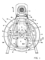
- Figure 1 shows a front view on a crate dryer according to the invention; and
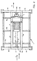
- Figure 2 shows a top view on the crate dryer of figure 1; and Figure 3 shows a side view on the crate dryer of figure 1 and 2.
-
- The
crate dryer 1 of the figures 1-3 comprises aframe 2, which at the front and at the rear comprises substantially A-shaped upright frames, havingbraces transverse beams 2g and 2h, respectively, and middle transverse beams 2i and 2j (not directly shown), respectively. - On top of the
frame 2 anelectro motor 3 has been mounted, with which a toothed belt pulley 4 is driven, over which toothed belt pulley 4 atoothed belt 6 runs which makes the toothed belt pulley 5 that is situated below rotate. The toothed belt pulley 5 is situated at the end of a rotatingshaft 7, which on both sides is journalled inbearings 12a, 12b that are attached to the middletransverse beams 2I and 2J of theframe 2. - The rotating
shaft 7 is attached to adrum 8, which is formed by an open frame, comprising afront ring 8a, amiddle ring 8b, and a rear ring 8c. For eachring 8a-8c atransverse beam 8d is provided, with which the ring is attached to the rotatingshaft 7. Furthermoreposts 8g, 8h, 8i, 8j and 8k, 8l that are also connected to therings 8a-8c, have each time been arranged in pairs extending upward and downward from thetransverse rods - The posts 8g-8l are provided with
holes 13, in whichbolt connections 14 may extend, with whichbolt connections 14angle sections 9a-9h can be attached to the posts 8g-8l, at the wanted level. - Said wanted level depends on the height of the crates K that have to be dried in the
device 1. - Around the
drum 8 ascreen 10 has been arranged, of which thecircular shells drip tray 11 is situated, on which the water can run off in the direction C in transverse direction and subsequently in the direction D in longitudinal direction, to a location of discharge that is not further shown. - When washed and dried crates have to be dried they are supplied in the direction A with means that are not shown to the drying device, and they are inserted into the bottom compartment, in figure 1 formed by
angle sections 9e-9h. In this example two crates after another can be inserted. Theangle sections 9e-9h here engage about the longitudinal edges of the crate K. Subsequently thedrum 8 is rotated over 180°, in order to bring the other compartments in front of the supply of crates. Two crates -in this example- are then inserted into it again, which crates then are kept confined by theangle sections 9a-9d. The drum, loaded with crates entirely on either side of therotating shaft 7, is then balanced. The drum is subsequently rotated with such speed that the centrifugal force is sufficient to throw the water off from the crates. As soon as this speed is reached, the drum is slowed down again. As soon as the drum has come to a standstill again, the centrifuged crates are moved out of the drum, in the direction E (see figure 2). As a result emptying the compartments can take place simultaneously with filling the same compartments, from the direction A. As a result operation time is saved on. - It will be understood that the capacity of the drum may be increased by making it longer and/or larger in diameter.
- Another option is placing
several drying devices 1 adjacent to each other and having them alternatingly operative such that the one device is loaded/unloaded and other is rotated.
Claims (8)
- Device (1) for drying washed and rinsed crates or cases (K), comprising a frame (2) and receiving or accommodation compartments for the crates or cases, in which the accommodation compartments are attached to a horizontally positioned rotating shaft (7) and are situated on either side of it in a symmetrical manner and in which the rotating shaft (7) is carried by the frame (2), furthermore comprising an electromotor (3) for rotating the rotating shaft (7) and thus the accommodation compartments in order to cast off the water present on the crates or cases (K) from them through centrifugal forces, wherein the device is provided with a crate feed (A) that opens parallel to the rotating shaft and with a crate exit (E) that opens parallel to the rotating shaft, characterized in that the crate feed (A) and the crate exit (E) are in line with each other and are located below the rotating shaft (7), wherein the electromotor (3) is arranged on the frame (2) radially spaced from the rotating shaft (7).
- Device according to claim 1, in which the accommodation compartments have boundaries (9a-h) that are adjustable in distance one to the other.
- Device according to claim 2, in which the boundaries of the accommodation compartments comprise angle sections (9a-h) destined for engaging about the longitudinal edges of the crates (K).
- Device according to any one of the claims 1-3, provided with a screen (10) stationary with the frame (2) for radially outward stopping of the water cast off from the crates (K).
- Device according to claim 4, provided with a oollection tray (11) for water intercepted by the screen (10).
- Assembly of a device according to any one of the preceding claims and a supply device for crates to be dried and a discharge device for dried crates, in which both the supply device and discharge device are in line with or can be brought in line with at least one accommodation compartment.
- Method for drying washed and rinsed crates or cases, wherein the crates or cases are fed into a device for drying washed and rinsed crates or cases according to any one of the claims 1-6, wherein one or more crates or cases are fed into a compartment, below the rotating shaft, the crates are dried by rotating said compartment with the rotating shaft, and wherein after the crates have been dried the rotation is stopped and the dried crates are removed from the compartment while simultanously one or more next crate or case are fed into that compartment.
- Method according to claim 7, wherein both compartments on either side of the rotating shaft are occupied with crates during rotation for drying the crates in both compartments.
Applications Claiming Priority (2)
| Application Number | Priority Date | Filing Date | Title |
|---|---|---|---|
| NL1014651 | 2000-03-15 | ||
| NL1014651A NL1014651C1 (en) | 2000-03-15 | 2000-03-15 | Crate dryer. |
Publications (3)
| Publication Number | Publication Date |
|---|---|
| EP1134527A2 EP1134527A2 (en) | 2001-09-19 |
| EP1134527A3 EP1134527A3 (en) | 2001-09-26 |
| EP1134527B1 true EP1134527B1 (en) | 2005-11-02 |
Family
ID=19771004
Family Applications (1)
| Application Number | Title | Priority Date | Filing Date |
|---|---|---|---|
| EP01200940A Expired - Lifetime EP1134527B1 (en) | 2000-03-15 | 2001-03-14 | Crate dryer |
Country Status (7)
| Country | Link |
|---|---|
| US (1) | US6446352B2 (en) |
| EP (1) | EP1134527B1 (en) |
| AT (1) | ATE308730T1 (en) |
| DE (1) | DE60114490T2 (en) |
| DK (1) | DK1134527T3 (en) |
| ES (1) | ES2254314T3 (en) |
| NL (1) | NL1014651C1 (en) |
Cited By (1)
| Publication number | Priority date | Publication date | Assignee | Title |
|---|---|---|---|---|
| CN110822843A (en) * | 2019-06-10 | 2020-02-21 | 新昌县乐意工艺品有限公司 | Drying device is used in handicraft production |
Families Citing this family (21)
| Publication number | Priority date | Publication date | Assignee | Title |
|---|---|---|---|---|
| US8157625B2 (en) | 2010-01-26 | 2012-04-17 | Foodmate Bv | Method and apparatus for collecting meat from an animal part |
| US8632380B2 (en) | 2010-01-26 | 2014-01-21 | Foodmate B.V. | Method and apparatus for removing a sleeve of meat from an animal part having bone with knuckles on each of its opposite ends |
| US8757354B2 (en) | 2010-04-19 | 2014-06-24 | Foodmate Bv | Turning block alignment |
| NL2004574C2 (en) | 2010-04-19 | 2011-10-20 | Foodmate B V | Rotatable article support for a conveyor. |
| NL2006075C2 (en) | 2011-01-26 | 2012-07-30 | Foodmate B V | Rotationally indexed article support for a conveyor system having an alignment station. |
| NL2004573C2 (en) | 2010-04-19 | 2011-10-20 | Foodmate B V | Turning block alignment. |
| US8789684B2 (en) | 2010-04-19 | 2014-07-29 | Foodmate Bv | Rotatable article support for a conveyor |
| US8727839B2 (en) | 2011-01-21 | 2014-05-20 | Foodmate Bv | Poultry wing cutter for narrow pitch poultry lines |
| US8882571B2 (en) | 2011-01-26 | 2014-11-11 | Foodmate Bv | Method of deboning animal thighs for separating and collecting meat therefrom and apparatus for performing the method |
| US8267241B2 (en) | 2011-01-26 | 2012-09-18 | Foodmate Bv | Rotationally indexed article support for a conveyor system having an alignment station |
| WO2012102609A1 (en) | 2011-01-26 | 2012-08-02 | Foodmate B.V. | Method of deboning animal thighs for separating and collecting meat there from and apparatus for performing the method |
| US8430728B2 (en) | 2011-02-14 | 2013-04-30 | Foodmate Bv | Special cut poultry wing cutter |
| NL2009033C2 (en) | 2012-06-19 | 2013-12-23 | Foodmate B V | Weighing method and apparatus. |
| US8808068B2 (en) | 2012-10-29 | 2014-08-19 | Foodmate Bv | Method of and system for automatically removing meat from an animal extremity |
| NL2009718C2 (en) | 2012-10-29 | 2014-05-01 | Foodmate B V | Method of mechanically removing skin from animal parts. |
| DK201370239A1 (en) | 2013-04-30 | 2014-10-31 | Semi Stål As | Container drying device |
| US9078453B2 (en) | 2013-11-01 | 2015-07-14 | Foodmate B.V. | Method and system for automatically deboning poultry breast caps containing meat and a skeletal structure to obtain breast fillets therefrom |
| US8961274B1 (en) | 2013-12-18 | 2015-02-24 | Foodmate Bv | Selective tendon cutter and method |
| JP7041011B2 (en) * | 2018-06-22 | 2022-03-23 | 株式会社スギノマシン | Dryer |
| DE102018117417B3 (en) * | 2018-07-18 | 2020-01-02 | Ludwig Bohrer Maschinenbau Gmbh | Device for drying objects and in particular boxes, crates and the like |
| DE102021102581A1 (en) | 2021-02-04 | 2022-08-04 | Klotzki Maschinenbau Gmbh | Treatment device for treating collapsible containers |
Family Cites Families (10)
| Publication number | Priority date | Publication date | Assignee | Title |
|---|---|---|---|---|
| US1599557A (en) | 1923-01-17 | 1926-09-14 | James A Craig | Tracked lumber drier |
| US1542929A (en) | 1924-01-07 | 1925-06-23 | Woolrich Edward | Centrifugal drier |
| US1756281A (en) | 1928-06-14 | 1930-04-29 | Frank W Cherrington | Method of drying or treating timber and the like |
| CH230766A (en) | 1943-06-26 | 1944-01-31 | Hobi Eberhard Anton | Rapid drying device for peat. |
| DE4140989A1 (en) | 1991-12-12 | 1992-07-02 | Guenter Martin Landesberger | Drying installation for crates - spin dries stacks after washing inside rotating cylinder driven by electromotor |
| US5675905A (en) * | 1996-06-14 | 1997-10-14 | The Great Northern Equipment Company Llc | Dryer system for vegetables |
| US6053351A (en) * | 1998-06-05 | 2000-04-25 | Dunton; Terry Lee | Plating basket with improved support structure |
| DE19833416A1 (en) | 1998-07-24 | 2000-01-27 | Guenter Landesberger | Crate-drying plant by centrifugal force consists of horizontal, sloping or vertical cylinders rotating and containing crates, with belts at varying speeds |
| US5992042A (en) * | 1998-11-20 | 1999-11-30 | Griffin Produce, Inc. | Dryer and method for drying harvested vegetables |
| US6112429A (en) * | 1998-11-20 | 2000-09-05 | Griffin Produce, Inc. | Method and apparatus for washing and drying harvested vegetables |
-
2000
- 2000-03-15 NL NL1014651A patent/NL1014651C1/en not_active IP Right Cessation
-
2001
- 2001-03-13 US US09/805,270 patent/US6446352B2/en not_active Expired - Fee Related
- 2001-03-14 ES ES01200940T patent/ES2254314T3/en not_active Expired - Lifetime
- 2001-03-14 DK DK01200940T patent/DK1134527T3/en active
- 2001-03-14 AT AT01200940T patent/ATE308730T1/en active
- 2001-03-14 DE DE60114490T patent/DE60114490T2/en not_active Expired - Lifetime
- 2001-03-14 EP EP01200940A patent/EP1134527B1/en not_active Expired - Lifetime
Cited By (1)
| Publication number | Priority date | Publication date | Assignee | Title |
|---|---|---|---|---|
| CN110822843A (en) * | 2019-06-10 | 2020-02-21 | 新昌县乐意工艺品有限公司 | Drying device is used in handicraft production |
Also Published As
| Publication number | Publication date |
|---|---|
| DE60114490D1 (en) | 2005-12-08 |
| ES2254314T3 (en) | 2006-06-16 |
| EP1134527A2 (en) | 2001-09-19 |
| DK1134527T3 (en) | 2006-03-20 |
| DE60114490T2 (en) | 2006-08-24 |
| ATE308730T1 (en) | 2005-11-15 |
| NL1014651C1 (en) | 2001-09-21 |
| US20010025429A1 (en) | 2001-10-04 |
| EP1134527A3 (en) | 2001-09-26 |
| US6446352B2 (en) | 2002-09-10 |
Similar Documents
| Publication | Publication Date | Title |
|---|---|---|
| EP1134527A2 (en) | Crate dryer | |
| CN108481158A (en) | A kind of ground and cleaned drying production line | |
| CN106006138B (en) | A kind of textile machinery portable batcher | |
| EP0087649A1 (en) | Machine for washing and drying fruit and/or vegetables | |
| US5802733A (en) | Dryer system for vegetables | |
| US4464846A (en) | Hydro-extracting apparatus for cheeses of yarn | |
| CN208504978U (en) | A kind of fish meal drying unit | |
| EP2116142B1 (en) | Apparatus for washing and drying leaf products and more generically vegetables | |
| CN207712853U (en) | A kind of fruit cleaning conveying integrated machine | |
| CN206196903U (en) | A kind of fully-automatic dewatering fruits and vegetables complete production line | |
| US3724091A (en) | Continuous production centrifuge | |
| CN210625131U (en) | Vertical spin dryer | |
| US1971979A (en) | Washing and drying machine | |
| US6260391B1 (en) | Laundry centrifuge, in particular for an automated washing range | |
| EP4409213A1 (en) | Centrifugal dryer machine | |
| EP2136171A2 (en) | Centrifugal machine | |
| CN114717785B (en) | Clothes making equipment and clothes making process | |
| US3799338A (en) | Leaf separator | |
| JP2990575B2 (en) | Inclined centrifugal dehydration drying method | |
| CN113525772A (en) | Quick air-dry facility of konjaku food bag | |
| CN221036612U (en) | Food package bag drying equipment | |
| CN111942624A (en) | Jar system hot pepper raw materials washs air-dries dress altar equipment | |
| CN110979855A (en) | Plastic packaging food screening device | |
| CN211619451U (en) | Processing device for clothing textile fabric | |
| US4900213A (en) | Centrifugal machine for discharging viscous products from cylindrical containers |
Legal Events
| Date | Code | Title | Description |
|---|---|---|---|
| PUAI | Public reference made under article 153(3) epc to a published international application that has entered the european phase |
Free format text: ORIGINAL CODE: 0009012 |
|
| PUAL | Search report despatched |
Free format text: ORIGINAL CODE: 0009013 |
|
| AK | Designated contracting states |
Kind code of ref document: A2 Designated state(s): AT BE CH CY DE DK ES FI FR GB GR IE IT LI LU MC NL PT SE TR |
|
| AX | Request for extension of the european patent |
Free format text: AL;LT;LV;MK;RO;SI |
|
| AK | Designated contracting states |
Kind code of ref document: A3 Designated state(s): AT BE CH CY DE DK ES FI FR GB GR IE IT LI LU MC NL PT SE TR |
|
| AX | Request for extension of the european patent |
Free format text: AL;LT;LV;MK;RO;SI |
|
| 17P | Request for examination filed |
Effective date: 20020221 |
|
| AKX | Designation fees paid |
Free format text: AT BE CH CY DE DK ES FI FR GB GR IE IT LI LU MC NL PT SE TR |
|
| 17Q | First examination report despatched |
Effective date: 20031127 |
|
| GRAP | Despatch of communication of intention to grant a patent |
Free format text: ORIGINAL CODE: EPIDOSNIGR1 |
|
| GRAS | Grant fee paid |
Free format text: ORIGINAL CODE: EPIDOSNIGR3 |
|
| GRAA | (expected) grant |
Free format text: ORIGINAL CODE: 0009210 |
|
| AK | Designated contracting states |
Kind code of ref document: B1 Designated state(s): AT BE CH CY DE DK ES FI FR GB GR IE IT LI LU MC NL PT SE TR |
|
| REG | Reference to a national code |
Ref country code: GB Ref legal event code: FG4D |
|
| REG | Reference to a national code |
Ref country code: CH Ref legal event code: EP |
|
| REF | Corresponds to: |
Ref document number: 60114490 Country of ref document: DE Date of ref document: 20051208 Kind code of ref document: P |
|
| PG25 | Lapsed in a contracting state [announced via postgrant information from national office to epo] |
Ref country code: GR Free format text: LAPSE BECAUSE OF FAILURE TO SUBMIT A TRANSLATION OF THE DESCRIPTION OR TO PAY THE FEE WITHIN THE PRESCRIBED TIME-LIMIT Effective date: 20060202 |
|
| REG | Reference to a national code |
Ref country code: SE Ref legal event code: TRGR |
|
| REG | Reference to a national code |
Ref country code: CH Ref legal event code: NV Representative=s name: E. BLUM & CO. PATENTANWAELTE |
|
| PG25 | Lapsed in a contracting state [announced via postgrant information from national office to epo] |
Ref country code: IE Free format text: LAPSE BECAUSE OF NON-PAYMENT OF DUE FEES Effective date: 20060314 |
|
| REG | Reference to a national code |
Ref country code: DK Ref legal event code: T3 |
|
| PG25 | Lapsed in a contracting state [announced via postgrant information from national office to epo] |
Ref country code: MC Free format text: LAPSE BECAUSE OF NON-PAYMENT OF DUE FEES Effective date: 20060331 Ref country code: LU Free format text: LAPSE BECAUSE OF NON-PAYMENT OF DUE FEES Effective date: 20060331 |
|
| PG25 | Lapsed in a contracting state [announced via postgrant information from national office to epo] |
Ref country code: PT Free format text: LAPSE BECAUSE OF FAILURE TO SUBMIT A TRANSLATION OF THE DESCRIPTION OR TO PAY THE FEE WITHIN THE PRESCRIBED TIME-LIMIT Effective date: 20060403 |
|
| REG | Reference to a national code |
Ref country code: ES Ref legal event code: FG2A Ref document number: 2254314 Country of ref document: ES Kind code of ref document: T3 |
|
| ET | Fr: translation filed | ||
| PLBE | No opposition filed within time limit |
Free format text: ORIGINAL CODE: 0009261 |
|
| STAA | Information on the status of an ep patent application or granted ep patent |
Free format text: STATUS: NO OPPOSITION FILED WITHIN TIME LIMIT |
|
| 26N | No opposition filed |
Effective date: 20060803 |
|
| REG | Reference to a national code |
Ref country code: IE Ref legal event code: MM4A |
|
| REG | Reference to a national code |
Ref country code: CH Ref legal event code: PFA Owner name: SYSTEMATE GROUP B.V. Free format text: SYSTEMATE GROUP B.V.#EDISONSTRAAT 1-3#3281 NC NUMANSDORP (NL) -TRANSFER TO- SYSTEMATE GROUP B.V.#EDISONSTRAAT 1-3#3281 NC NUMANSDORP (NL) |
|
| PG25 | Lapsed in a contracting state [announced via postgrant information from national office to epo] |
Ref country code: CY Free format text: LAPSE BECAUSE OF FAILURE TO SUBMIT A TRANSLATION OF THE DESCRIPTION OR TO PAY THE FEE WITHIN THE PRESCRIBED TIME-LIMIT Effective date: 20051102 |
|
| NLS | Nl: assignments of ep-patents |
Owner name: NUMAFA HOLDING B.V. Effective date: 20090714 Owner name: POLYLOGISTICS HOLDING B.V. Effective date: 20090714 |
|
| REG | Reference to a national code |
Ref country code: CH Ref legal event code: PUE Owner name: NUMAFA HOLDING B.V. Free format text: SYSTEMATE GROUP B.V.#EDISONSTRAAT 1-3#3281 NC NUMANSDORP (NL) -TRANSFER TO- NUMAFA HOLDING B.V.#EDISONSTRAAT 1#3281 NC NUMANSDORP (NL) Ref country code: CH Ref legal event code: PUE Owner name: POLYLOGISTICS HOLDING B.V. Free format text: NUMAFA HOLDING B.V.#EDISONSTRAAT 1#3281 NC NUMANSDORP (NL) -TRANSFER TO- POLYLOGISTICS HOLDING B.V.#INDUSTRIEPARK 1#7021 BK ZELHEM (NL) |
|
| REG | Reference to a national code |
Ref country code: GB Ref legal event code: 732E Free format text: REGISTERED BETWEEN 20091029 AND 20091104 |
|
| REG | Reference to a national code |
Ref country code: ES Ref legal event code: PC2A |
|
| REG | Reference to a national code |
Ref country code: GB Ref legal event code: 732E Free format text: REGISTERED BETWEEN 20091105 AND 20091111 |
|
| REG | Reference to a national code |
Ref country code: FR Ref legal event code: TP |
|
| PGFP | Annual fee paid to national office [announced via postgrant information from national office to epo] |
Ref country code: CH Payment date: 20110228 Year of fee payment: 11 Ref country code: TR Payment date: 20110307 Year of fee payment: 11 Ref country code: IT Payment date: 20110312 Year of fee payment: 11 Ref country code: AT Payment date: 20110325 Year of fee payment: 11 Ref country code: FR Payment date: 20110316 Year of fee payment: 11 Ref country code: FI Payment date: 20110321 Year of fee payment: 11 |
|
| PGFP | Annual fee paid to national office [announced via postgrant information from national office to epo] |
Ref country code: ES Payment date: 20110228 Year of fee payment: 11 |
|
| PG25 | Lapsed in a contracting state [announced via postgrant information from national office to epo] |
Ref country code: FI Free format text: LAPSE BECAUSE OF NON-PAYMENT OF DUE FEES Effective date: 20120314 |
|
| REG | Reference to a national code |
Ref country code: CH Ref legal event code: PL |
|
| BECH | Be: change of holder |
Owner name: NUMAFA CLEANING AND AUTOMATION B.V. Effective date: 20121119 |
|
| REG | Reference to a national code |
Ref country code: AT Ref legal event code: MM01 Ref document number: 308730 Country of ref document: AT Kind code of ref document: T Effective date: 20120314 |
|
| REG | Reference to a national code |
Ref country code: FR Ref legal event code: ST Effective date: 20121130 |
|
| REG | Reference to a national code |
Ref country code: GB Ref legal event code: 732E Free format text: REGISTERED BETWEEN 20121129 AND 20121205 |
|
| REG | Reference to a national code |
Ref country code: NL Ref legal event code: SD Effective date: 20121228 |
|
| PG25 | Lapsed in a contracting state [announced via postgrant information from national office to epo] |
Ref country code: LI Free format text: LAPSE BECAUSE OF NON-PAYMENT OF DUE FEES Effective date: 20120331 Ref country code: FR Free format text: LAPSE BECAUSE OF NON-PAYMENT OF DUE FEES Effective date: 20120402 Ref country code: CH Free format text: LAPSE BECAUSE OF NON-PAYMENT OF DUE FEES Effective date: 20120331 Ref country code: AT Free format text: LAPSE BECAUSE OF NON-PAYMENT OF DUE FEES Effective date: 20120314 |
|
| REG | Reference to a national code |
Ref country code: NL Ref legal event code: GRER Effective date: 20130219 |
|
| PG25 | Lapsed in a contracting state [announced via postgrant information from national office to epo] |
Ref country code: IT Free format text: LAPSE BECAUSE OF NON-PAYMENT OF DUE FEES Effective date: 20120314 |
|
| REG | Reference to a national code |
Ref country code: DE Ref legal event code: R081 Ref document number: 60114490 Country of ref document: DE Owner name: NUMAFA CLEANING AND AUTOMATION B.V., NL Free format text: FORMER OWNER: POLYLOGISTICS HOLDING B.V., ZELHEM, NL Effective date: 20130117 Ref country code: DE Ref legal event code: R082 Ref document number: 60114490 Country of ref document: DE Representative=s name: WEICKMANN & WEICKMANN, DE Effective date: 20130117 Ref country code: DE Ref legal event code: R082 Ref document number: 60114490 Country of ref document: DE Representative=s name: PATENTANWAELTE WEICKMANN & WEICKMANN, DE Effective date: 20130117 Ref country code: DE Ref legal event code: R082 Ref document number: 60114490 Country of ref document: DE Representative=s name: WEICKMANN & WEICKMANN PATENT- UND RECHTSANWAEL, DE Effective date: 20130117 |
|
| PGFP | Annual fee paid to national office [announced via postgrant information from national office to epo] |
Ref country code: DK Payment date: 20130215 Year of fee payment: 13 Ref country code: DE Payment date: 20130325 Year of fee payment: 13 Ref country code: SE Payment date: 20130322 Year of fee payment: 13 Ref country code: GB Payment date: 20130313 Year of fee payment: 13 |
|
| PGFP | Annual fee paid to national office [announced via postgrant information from national office to epo] |
Ref country code: NL Payment date: 20130327 Year of fee payment: 13 |
|
| PGFP | Annual fee paid to national office [announced via postgrant information from national office to epo] |
Ref country code: BE Payment date: 20130326 Year of fee payment: 13 |
|
| REG | Reference to a national code |
Ref country code: ES Ref legal event code: FD2A Effective date: 20130826 |
|
| PG25 | Lapsed in a contracting state [announced via postgrant information from national office to epo] |
Ref country code: ES Free format text: LAPSE BECAUSE OF NON-PAYMENT OF DUE FEES Effective date: 20120315 |
|
| PG25 | Lapsed in a contracting state [announced via postgrant information from national office to epo] |
Ref country code: TR Free format text: LAPSE BECAUSE OF NON-PAYMENT OF DUE FEES Effective date: 20120314 |
|
| REG | Reference to a national code |
Ref country code: DE Ref legal event code: R119 Ref document number: 60114490 Country of ref document: DE |
|
| REG | Reference to a national code |
Ref country code: DK Ref legal event code: EBP Effective date: 20140331 |
|
| REG | Reference to a national code |
Ref country code: NL Ref legal event code: V1 Effective date: 20141001 |
|
| REG | Reference to a national code |
Ref country code: SE Ref legal event code: EUG |
|
| GBPC | Gb: european patent ceased through non-payment of renewal fee |
Effective date: 20140314 |
|
| PG25 | Lapsed in a contracting state [announced via postgrant information from national office to epo] |
Ref country code: SE Free format text: LAPSE BECAUSE OF NON-PAYMENT OF DUE FEES Effective date: 20140315 |
|
| REG | Reference to a national code |
Ref country code: DE Ref legal event code: R119 Ref document number: 60114490 Country of ref document: DE Effective date: 20141001 |
|
| PG25 | Lapsed in a contracting state [announced via postgrant information from national office to epo] |
Ref country code: DE Free format text: LAPSE BECAUSE OF NON-PAYMENT OF DUE FEES Effective date: 20141001 Ref country code: GB Free format text: LAPSE BECAUSE OF NON-PAYMENT OF DUE FEES Effective date: 20140314 |
|
| PG25 | Lapsed in a contracting state [announced via postgrant information from national office to epo] |
Ref country code: NL Free format text: LAPSE BECAUSE OF NON-PAYMENT OF DUE FEES Effective date: 20141001 |
|
| PG25 | Lapsed in a contracting state [announced via postgrant information from national office to epo] |
Ref country code: DK Free format text: LAPSE BECAUSE OF NON-PAYMENT OF DUE FEES Effective date: 20140331 |
|
| PG25 | Lapsed in a contracting state [announced via postgrant information from national office to epo] |
Ref country code: BE Free format text: LAPSE BECAUSE OF NON-PAYMENT OF DUE FEES Effective date: 20140331 |