EP1134476A1 - Rohrkruemmer fuer abfuehrende Anlagen - Google Patents
Rohrkruemmer fuer abfuehrende Anlagen Download PDFInfo
- Publication number
- EP1134476A1 EP1134476A1 EP01200939A EP01200939A EP1134476A1 EP 1134476 A1 EP1134476 A1 EP 1134476A1 EP 01200939 A EP01200939 A EP 01200939A EP 01200939 A EP01200939 A EP 01200939A EP 1134476 A1 EP1134476 A1 EP 1134476A1
- Authority
- EP
- European Patent Office
- Prior art keywords
- bend
- partitions
- inner tube
- outer tube
- bend according
- Prior art date
- Legal status (The legal status is an assumption and is not a legal conclusion. Google has not performed a legal analysis and makes no representation as to the accuracy of the status listed.)
- Withdrawn
Links
- 238000007599 discharging Methods 0.000 title 1
- 238000005192 partition Methods 0.000 claims abstract description 29
- 238000002485 combustion reaction Methods 0.000 claims abstract description 10
- 239000007789 gas Substances 0.000 description 8
- 125000006850 spacer group Chemical group 0.000 description 3
- 230000004308 accommodation Effects 0.000 description 2
- 238000003466 welding Methods 0.000 description 2
- 239000000567 combustion gas Substances 0.000 description 1
- 239000003292 glue Substances 0.000 description 1
- 238000002347 injection Methods 0.000 description 1
- 239000007924 injection Substances 0.000 description 1
- 238000004519 manufacturing process Methods 0.000 description 1
Images

Classifications
-
- F—MECHANICAL ENGINEERING; LIGHTING; HEATING; WEAPONS; BLASTING
- F16—ENGINEERING ELEMENTS AND UNITS; GENERAL MEASURES FOR PRODUCING AND MAINTAINING EFFECTIVE FUNCTIONING OF MACHINES OR INSTALLATIONS; THERMAL INSULATION IN GENERAL
- F16L—PIPES; JOINTS OR FITTINGS FOR PIPES; SUPPORTS FOR PIPES, CABLES OR PROTECTIVE TUBING; MEANS FOR THERMAL INSULATION IN GENERAL
- F16L39/00—Joints or fittings for double-walled or multi-channel pipes or pipe assemblies
- F16L39/005—Joints or fittings for double-walled or multi-channel pipes or pipe assemblies for concentric pipes
-
- F—MECHANICAL ENGINEERING; LIGHTING; HEATING; WEAPONS; BLASTING
- F15—FLUID-PRESSURE ACTUATORS; HYDRAULICS OR PNEUMATICS IN GENERAL
- F15D—FLUID DYNAMICS, i.e. METHODS OR MEANS FOR INFLUENCING THE FLOW OF GASES OR LIQUIDS
- F15D1/00—Influencing flow of fluids
- F15D1/02—Influencing flow of fluids in pipes or conduits
- F15D1/04—Arrangements of guide vanes in pipe elbows or duct bends; Construction of pipe conduit elements for elbows with respect to flow, e.g. for reducing losses of flow
-
- F—MECHANICAL ENGINEERING; LIGHTING; HEATING; WEAPONS; BLASTING
- F16—ENGINEERING ELEMENTS AND UNITS; GENERAL MEASURES FOR PRODUCING AND MAINTAINING EFFECTIVE FUNCTIONING OF MACHINES OR INSTALLATIONS; THERMAL INSULATION IN GENERAL
- F16L—PIPES; JOINTS OR FITTINGS FOR PIPES; SUPPORTS FOR PIPES, CABLES OR PROTECTIVE TUBING; MEANS FOR THERMAL INSULATION IN GENERAL
- F16L43/00—Bends; Siphons
- F16L43/001—Bends; Siphons made of metal
Definitions
- the invention relates to a bend for accommodation in lines between closed gas or oil appliances and debouching structures for them.
- This may for instance regard lines to a facade debouching structure, in which the bend usually has to bridge 90 degrees, or lines to vertical debouching structures, in which with the help of two oppositely placed bends a -horizontal- buckle in the line is being realised.
- both the outer tube and the inner tube consist of two identical halves divided according to a plane of symmetry or main plane.
- each inner tube half is provided with two opposite spacer partitions which extend to the outer tube and follow the curve.
- both outer tube halves are placed around it and they are welded or riveted to each other and to the partitions.
- Said known bend relatively has a lot of parts and as a result requires a lot of work to assemble.
- the spacer partitions hardly cooperate in the promotion of the flow of air or gas trough the curve, they rather seem to increase the resistance against it.
- a bend having a sharp buckle is known, in which at the location of the buckle area between the inner tube and the outer tube four radial spacer partitions are present, that are each time at 90 degrees with respect to each other.
- the resistance against air/gas flow is increased here because of the partitions that lie in the plane of symmetry and also because of the buckled partitions that are transverse to them.
- the invention provides a bend for debouching structures of closed gas or oil appliances having an inner tube for discharge of combustion air and an outer tube placed around the inner tube, the outer tube being placed concentrically around the inner tube in order to define therewith an annular line for supply of combustion air to the gas or oil appliance, in which the inner tube and the outer tube have a fluently curved course in a main plane and in which only transverse to the main plane air guidance partitions are present in the annular space, which guidance partitions substantially follow the curve of the bend.
- the flow conditions are further optimized when the partitions -considered in cross-section- are situated straight opposite each other.
- the flow conditions are even further improved when the partitions are situated radially perpendicular to the main plane.
- the main plane forms a plane of symmetry of the bend.
- the partitions are formed integral with the inner tube.
- the partitions can then be a placement aid for it.
- Assembling can be facilitated when the outer tube is longitudinally divided, preferably according to the plane of symmetry.
- an inner tube 1 bent in a fluent manner over an angle ⁇ is shown having a straight first end section 2, before the bent middle section 3 and a straight second end section 4. With the circular end edges 5 and 6, respectively, the inner tube 1 can be connected to the other inner tubes of a debouching structure or line for a closed gas or oil appliance.
- the inner tube 1 has a plane of symmetry 8, in which plane the curvature is situated as well.
- a partition 7 is formed integral with the inner tube 1, the partition having a fluently bent middle section 10 with thickened ends 11 and with end sections 9 that incline radially to the inside. It will be understood that diametrally opposite, on the other side of the inner tube 1, a similar partition has been formed.
- the curves of the inner tube 1 and the middle tube 1 -in projection on plane 8- at least almost have the same centre M.
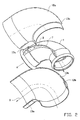
- the inner tube 1 (it is noted that the inner tube in this figure -contrary to figure 1- is provided with a socket at both ends) is accommodated in an outer tube 12a, 12b, in this case consisting of two identical halves which can be connected to each other beforehand or by the fitter, for instance by means of glue or screws. When this is done beforehand, welding can also be used.
- the inner tube 1 can for instance permit a discharge for combustion gasses pass in the direction A, whereas the annular space formed between the outer tube 12a, b, and the inner tube 1 can be used for a supply flow of combustion air in the direction B.
- the fluently bent guidance partitions 7 not only ensure accurate placement of the outer tube 12a, b, but also a fluent guidance for the combustion air along the flow path B, so that resistance losses are limited to a minimum.
- the bend in this example forms an angle ⁇ of 90 degrees.
- ⁇ 90 degrees.
- use can also be made of two bends of 45 degrees placed opposite each other and to be connected to each other.
- outer tube as one unity.
- the outer tube instead of the inner tube can be provided with the guidance partitions 7 formed integral with the inner surface, which can take place in a very simple manner when use is made of an outer tube having two longitudinal halves, such as halves 12a, 12b of figure 2.
Landscapes
- Engineering & Computer Science (AREA)
- General Engineering & Computer Science (AREA)
- Mechanical Engineering (AREA)
- Physics & Mathematics (AREA)
- Fluid Mechanics (AREA)
- Rigid Pipes And Flexible Pipes (AREA)
Applications Claiming Priority (2)
| Application Number | Priority Date | Filing Date | Title |
|---|---|---|---|
| NL1014637A NL1014637C2 (nl) | 2000-03-14 | 2000-03-14 | Bochtstuk voor uitmondingsconstructies. |
| NL1014637 | 2000-03-14 |
Publications (1)
| Publication Number | Publication Date |
|---|---|
| EP1134476A1 true EP1134476A1 (de) | 2001-09-19 |
Family
ID=19770995
Family Applications (1)
| Application Number | Title | Priority Date | Filing Date |
|---|---|---|---|
| EP01200939A Withdrawn EP1134476A1 (de) | 2000-03-14 | 2001-03-14 | Rohrkruemmer fuer abfuehrende Anlagen |
Country Status (2)
| Country | Link |
|---|---|
| EP (1) | EP1134476A1 (de) |
| NL (1) | NL1014637C2 (de) |
Cited By (7)
| Publication number | Priority date | Publication date | Assignee | Title |
|---|---|---|---|---|
| GB2383389A (en) * | 2001-12-22 | 2003-06-25 | Glynwed Pipe Systems Ltd | Duckfoot Bend Assembly |
| EP3217060A1 (de) * | 2016-03-11 | 2017-09-13 | Centrotherm Systemtechnik GmbH | Doppelrohrbogensystem |
| WO2020112215A1 (en) * | 2018-11-29 | 2020-06-04 | Vortex Pipe Systems LLC | Material flow amplifier |
| US11002301B1 (en) | 2020-09-15 | 2021-05-11 | Vortex Pipe Systems LLC | Material flow modifier and apparatus comprising same |
| US11221028B1 (en) | 2018-11-29 | 2022-01-11 | Vortex Pipe Systems LLC | Cyclonic flow-inducing pump |
| US11378110B1 (en) | 2022-01-05 | 2022-07-05 | Vortex Pipe Systems LLC | Flexible fluid flow modifying device |
| US11739774B1 (en) | 2023-01-30 | 2023-08-29 | Vortex Pipe Systems LLC | Flow modifying device with performance enhancing vane structure |
Citations (4)
| Publication number | Priority date | Publication date | Assignee | Title |
|---|---|---|---|---|
| US2374815A (en) * | 1943-07-30 | 1945-05-01 | Breeze Corp | Spring coupling |
| DE9101646U1 (de) * | 1990-02-20 | 1991-05-02 | Joh. Vaillant Gmbh U. Co, 5630 Remscheid | Verbindungsbogen |
| US5186502A (en) * | 1990-12-11 | 1993-02-16 | Fibercast Company | Double-containment pipe fittings and system |
| EP0867652A2 (de) * | 1997-03-18 | 1998-09-30 | L.N. di NATALINI LINO & C. - S.r.l. | Rohranschluss für konzentrische Röhre, der aus zwei koaxialen Rohrbogen besteht |
-
2000
- 2000-03-14 NL NL1014637A patent/NL1014637C2/nl not_active IP Right Cessation
-
2001
- 2001-03-14 EP EP01200939A patent/EP1134476A1/de not_active Withdrawn
Patent Citations (5)
| Publication number | Priority date | Publication date | Assignee | Title |
|---|---|---|---|---|
| US2374815A (en) * | 1943-07-30 | 1945-05-01 | Breeze Corp | Spring coupling |
| DE9101646U1 (de) * | 1990-02-20 | 1991-05-02 | Joh. Vaillant Gmbh U. Co, 5630 Remscheid | Verbindungsbogen |
| US5186502A (en) * | 1990-12-11 | 1993-02-16 | Fibercast Company | Double-containment pipe fittings and system |
| US5186502B1 (en) * | 1990-12-11 | 1994-08-30 | Fibercast Co | Double-containment pipe fittings and system |
| EP0867652A2 (de) * | 1997-03-18 | 1998-09-30 | L.N. di NATALINI LINO & C. - S.r.l. | Rohranschluss für konzentrische Röhre, der aus zwei koaxialen Rohrbogen besteht |
Cited By (21)
| Publication number | Priority date | Publication date | Assignee | Title |
|---|---|---|---|---|
| GB2383389A (en) * | 2001-12-22 | 2003-06-25 | Glynwed Pipe Systems Ltd | Duckfoot Bend Assembly |
| GB2383389B (en) * | 2001-12-22 | 2005-04-06 | Glynwed Pipe Systems Ltd | Duckfoot bend assembly |
| EP3217060A1 (de) * | 2016-03-11 | 2017-09-13 | Centrotherm Systemtechnik GmbH | Doppelrohrbogensystem |
| US11319974B2 (en) | 2018-11-29 | 2022-05-03 | Vortex Pipe Systems LLC | Clamshell material flow amplifier |
| US11391309B2 (en) | 2018-11-29 | 2022-07-19 | Vortex Pipe Systems LLC | Material flow amplifier |
| US10890200B2 (en) | 2018-11-29 | 2021-01-12 | Vortex Pipe Systems LLC | Clamshell material flow amplifier |
| US10895274B2 (en) | 2018-11-29 | 2021-01-19 | Vortex Pipe Systems LLC | Material flow amplifier |
| US12497981B2 (en) | 2018-11-29 | 2025-12-16 | Vortex Pipe Systems LLC | Material flow amplifier |
| AU2021204411B2 (en) * | 2018-11-29 | 2021-08-05 | Vortex Pipe Systems LLC | Material flow amplifier |
| US11221028B1 (en) | 2018-11-29 | 2022-01-11 | Vortex Pipe Systems LLC | Cyclonic flow-inducing pump |
| WO2020112215A1 (en) * | 2018-11-29 | 2020-06-04 | Vortex Pipe Systems LLC | Material flow amplifier |
| US12404884B2 (en) | 2018-11-29 | 2025-09-02 | Vortex Pipe Systems LLC | Cyclonic flow-inducing pump |
| US10683881B1 (en) | 2018-11-29 | 2020-06-16 | Vortex Pipe Systems LLC | Material flow amplifier |
| US12012980B2 (en) | 2018-11-29 | 2024-06-18 | Vortex Pipe Systems LLC | Cyclonic flow-inducing pump |
| US12006957B2 (en) | 2018-11-29 | 2024-06-11 | Vortex Pipe Systems LLC | Material flow amplifier |
| US11976678B2 (en) | 2020-09-15 | 2024-05-07 | Vortex Pipe Systems LLC | Material flow modifier and apparatus comprising same |
| US11624381B2 (en) | 2020-09-15 | 2023-04-11 | Vortex Pipe Systems LLC | Material flow modifier and apparatus comprising same |
| US12359684B2 (en) | 2020-09-15 | 2025-07-15 | Vortex Pipe Systems LLC | Material flow modifier and apparatus comprising same |
| US11002301B1 (en) | 2020-09-15 | 2021-05-11 | Vortex Pipe Systems LLC | Material flow modifier and apparatus comprising same |
| US11378110B1 (en) | 2022-01-05 | 2022-07-05 | Vortex Pipe Systems LLC | Flexible fluid flow modifying device |
| US11739774B1 (en) | 2023-01-30 | 2023-08-29 | Vortex Pipe Systems LLC | Flow modifying device with performance enhancing vane structure |
Also Published As
| Publication number | Publication date |
|---|---|
| NL1014637C2 (nl) | 2001-09-17 |
Similar Documents
| Publication | Publication Date | Title |
|---|---|---|
| US2823703A (en) | Flexible pipe | |
| SU843785A3 (ru) | Выпр митель потока в газопроводе перед расходомером | |
| DE502007001965D1 (de) | Es element einer lenkspindel und verfahren zu dessen herstellung | |
| EP1134476A1 (de) | Rohrkruemmer fuer abfuehrende Anlagen | |
| PT93854A (pt) | Silencioso modular | |
| US5328213A (en) | Adjustable pipe fitting | |
| US11248513B2 (en) | Silencer insert, silencer comprising the same and method for manufacturing a silencer insert | |
| US9938873B2 (en) | Muffler for automobile | |
| CN108603727B (zh) | 具有双同心管环的热交换器 | |
| RU2017113424A (ru) | Системы и способы удержания труб для выхлопных газов | |
| CA2963100C (en) | Prefabricated, modular, fire resistance and non-fire resistance rated ventilation duct assembly with integral subducts | |
| EP0083910A1 (de) | Flexible Metallschlauchanordnung durch welche gashaltige Medien mit hohen Temperaturen durchströmen | |
| US1984172A (en) | Pipe bend | |
| JP3255396U (ja) | 煙突 | |
| US1981895A (en) | Boiler | |
| GB2263563A (en) | Flow straightener in the air induction pipe of an internal combustion engine | |
| US3688759A (en) | Outer building wall air heating device with a heat exchanger | |
| RU1773279C (ru) | Глушитель шума газового потока | |
| US2051323A (en) | Stovepipe | |
| ATE285515T1 (de) | Saugrohranlage mit mehreren leitungen | |
| US12305547B2 (en) | Sound attenuator as well as elements and a method of production thereof | |
| TH170616A (th) | โครงสร้างที่ใช้ควบต่อท่อ | |
| RU2000533C1 (ru) | Теплообменна труба с размещенной внутри вставкой | |
| TH67557B (th) | โครงสร้างที่ใช้ควบต่อท่อ | |
| KR200360534Y1 (ko) | 난방 시스템용 히팅 패널 어셈블리 |
Legal Events
| Date | Code | Title | Description |
|---|---|---|---|
| PUAI | Public reference made under article 153(3) epc to a published international application that has entered the european phase |
Free format text: ORIGINAL CODE: 0009012 |
|
| AK | Designated contracting states |
Kind code of ref document: A1 Designated state(s): FR GB IT Kind code of ref document: A1 Designated state(s): AT BE CH CY DE DK ES FI FR GB GR IE IT LI LU MC NL PT SE TR |
|
| AX | Request for extension of the european patent |
Free format text: AL;LT;LV;MK;RO;SI |
|
| 17P | Request for examination filed |
Effective date: 20020103 |
|
| AKX | Designation fees paid |
Free format text: FR GB IT |
|
| REG | Reference to a national code |
Ref country code: DE Ref legal event code: 8566 |
|
| STAA | Information on the status of an ep patent application or granted ep patent |
Free format text: STATUS: THE APPLICATION IS DEEMED TO BE WITHDRAWN |
|
| 18D | Application deemed to be withdrawn |
Effective date: 20041001 |