EP1134405A2 - Improved structure of fuel injector adjustable in fuel jet characteristic - Google Patents
Improved structure of fuel injector adjustable in fuel jet characteristic Download PDFInfo
- Publication number
- EP1134405A2 EP1134405A2 EP01105661A EP01105661A EP1134405A2 EP 1134405 A2 EP1134405 A2 EP 1134405A2 EP 01105661 A EP01105661 A EP 01105661A EP 01105661 A EP01105661 A EP 01105661A EP 1134405 A2 EP1134405 A2 EP 1134405A2
- Authority
- EP
- European Patent Office
- Prior art keywords
- fuel
- urging
- valve
- pressure
- control valve
- Prior art date
- Legal status (The legal status is an assumption and is not a legal conclusion. Google has not performed a legal analysis and makes no representation as to the accuracy of the status listed.)
- Granted
Links
- 239000000446 fuel Substances 0.000 title claims abstract description 471
- 239000007921 spray Substances 0.000 claims abstract description 127
- 238000002347 injection Methods 0.000 claims abstract description 115
- 239000007924 injection Substances 0.000 claims abstract description 115
- 230000008859 change Effects 0.000 claims abstract description 22
- 230000007246 mechanism Effects 0.000 claims description 151
- 239000007788 liquid Substances 0.000 claims description 82
- 238000012360 testing method Methods 0.000 claims description 80
- 238000000034 method Methods 0.000 claims description 43
- 239000012530 fluid Substances 0.000 claims description 33
- 238000004891 communication Methods 0.000 claims description 32
- 238000005507 spraying Methods 0.000 claims description 11
- 230000003247 decreasing effect Effects 0.000 claims description 10
- 230000007423 decrease Effects 0.000 description 5
- 230000000977 initiatory effect Effects 0.000 description 5
- 230000001105 regulatory effect Effects 0.000 description 4
- 239000002828 fuel tank Substances 0.000 description 3
- 230000009471 action Effects 0.000 description 2
- 230000033228 biological regulation Effects 0.000 description 2
- 230000000717 retained effect Effects 0.000 description 2
- 238000007789 sealing Methods 0.000 description 2
- 241001481828 Glyptocephalus cynoglossus Species 0.000 description 1
- 238000002485 combustion reaction Methods 0.000 description 1
- 230000001276 controlling effect Effects 0.000 description 1
- 239000000498 cooling water Substances 0.000 description 1
- 238000010586 diagram Methods 0.000 description 1
- 238000003780 insertion Methods 0.000 description 1
- 230000037431 insertion Effects 0.000 description 1
- 238000007689 inspection Methods 0.000 description 1
- 238000009434 installation Methods 0.000 description 1
- 238000012986 modification Methods 0.000 description 1
- 230000004048 modification Effects 0.000 description 1
- 230000009467 reduction Effects 0.000 description 1
- 230000000630 rising effect Effects 0.000 description 1
- 238000011144 upstream manufacturing Methods 0.000 description 1
Images




Classifications
-
- F—MECHANICAL ENGINEERING; LIGHTING; HEATING; WEAPONS; BLASTING
- F02—COMBUSTION ENGINES; HOT-GAS OR COMBUSTION-PRODUCT ENGINE PLANTS
- F02M—SUPPLYING COMBUSTION ENGINES IN GENERAL WITH COMBUSTIBLE MIXTURES OR CONSTITUENTS THEREOF
- F02M61/00—Fuel-injectors not provided for in groups F02M39/00 - F02M57/00 or F02M67/00
- F02M61/16—Details not provided for in, or of interest apart from, the apparatus of groups F02M61/02 - F02M61/14
- F02M61/168—Assembling; Disassembling; Manufacturing; Adjusting
-
- F—MECHANICAL ENGINEERING; LIGHTING; HEATING; WEAPONS; BLASTING
- F02—COMBUSTION ENGINES; HOT-GAS OR COMBUSTION-PRODUCT ENGINE PLANTS
- F02M—SUPPLYING COMBUSTION ENGINES IN GENERAL WITH COMBUSTIBLE MIXTURES OR CONSTITUENTS THEREOF
- F02M47/00—Fuel-injection apparatus operated cyclically with fuel-injection valves actuated by fluid pressure
- F02M47/02—Fuel-injection apparatus operated cyclically with fuel-injection valves actuated by fluid pressure of accumulator-injector type, i.e. having fuel pressure of accumulator tending to open, and fuel pressure in other chamber tending to close, injection valves and having means for periodically releasing that closing pressure
- F02M47/027—Electrically actuated valves draining the chamber to release the closing pressure
-
- F—MECHANICAL ENGINEERING; LIGHTING; HEATING; WEAPONS; BLASTING
- F02—COMBUSTION ENGINES; HOT-GAS OR COMBUSTION-PRODUCT ENGINE PLANTS
- F02M—SUPPLYING COMBUSTION ENGINES IN GENERAL WITH COMBUSTIBLE MIXTURES OR CONSTITUENTS THEREOF
- F02M63/00—Other fuel-injection apparatus having pertinent characteristics not provided for in groups F02M39/00 - F02M57/00 or F02M67/00; Details, component parts, or accessories of fuel-injection apparatus, not provided for in, or of interest apart from, the apparatus of groups F02M39/00 - F02M61/00 or F02M67/00; Combination of fuel pump with other devices, e.g. lubricating oil pump
- F02M63/0012—Valves
- F02M63/0014—Valves characterised by the valve actuating means
- F02M63/0015—Valves characterised by the valve actuating means electrical, e.g. using solenoid
- F02M63/0017—Valves characterised by the valve actuating means electrical, e.g. using solenoid using electromagnetic operating means
-
- F—MECHANICAL ENGINEERING; LIGHTING; HEATING; WEAPONS; BLASTING
- F02—COMBUSTION ENGINES; HOT-GAS OR COMBUSTION-PRODUCT ENGINE PLANTS
- F02M—SUPPLYING COMBUSTION ENGINES IN GENERAL WITH COMBUSTIBLE MIXTURES OR CONSTITUENTS THEREOF
- F02M2200/00—Details of fuel-injection apparatus, not otherwise provided for
- F02M2200/50—Arrangements of springs for valves used in fuel injectors or fuel injection pumps
- F02M2200/507—Adjusting spring tension by screwing spring seats
-
- F—MECHANICAL ENGINEERING; LIGHTING; HEATING; WEAPONS; BLASTING
- F02—COMBUSTION ENGINES; HOT-GAS OR COMBUSTION-PRODUCT ENGINE PLANTS
- F02M—SUPPLYING COMBUSTION ENGINES IN GENERAL WITH COMBUSTIBLE MIXTURES OR CONSTITUENTS THEREOF
- F02M2200/00—Details of fuel-injection apparatus, not otherwise provided for
- F02M2200/80—Fuel injection apparatus manufacture, repair or assembly
- F02M2200/8076—Fuel injection apparatus manufacture, repair or assembly involving threaded members
-
- F—MECHANICAL ENGINEERING; LIGHTING; HEATING; WEAPONS; BLASTING
- F02—COMBUSTION ENGINES; HOT-GAS OR COMBUSTION-PRODUCT ENGINE PLANTS
- F02M—SUPPLYING COMBUSTION ENGINES IN GENERAL WITH COMBUSTIBLE MIXTURES OR CONSTITUENTS THEREOF
- F02M2200/00—Details of fuel-injection apparatus, not otherwise provided for
- F02M2200/80—Fuel injection apparatus manufacture, repair or assembly
- F02M2200/8092—Fuel injection apparatus manufacture, repair or assembly adjusting or calibration
Definitions
- the air gap adjusting mechanism is made of a hollow member fitted on the injector body.
- the width of the first drive pulse signal is longer than that required to move the nozzle valve until a maximum rate of a jet of the test liquid from the spray hole is reached.
- the width of the first drive pulse signal is longer than that required to move the nozzle valve until a maximum rate of a jet of the test liquid from the spray hole is reached.
- the fuel flow area of the spray hole 12b is smaller than the fuel flow seat area, so that the rate of fuel injection depends upon the fuel flow area of the spray hole 12b.
- the amount of lift of the nozzle valve 20 decreases with time, while the rate of fuel injection is kept constant.
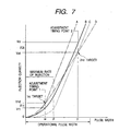
- the curve A indicates the injection quantity of the fuel injector 1 when the spring pressure of the spring 38 is so adjusted by the adjusting screw 37 as to have the injection quantity reach a target one determined only at the adjustment timing point 1 .
- the curve B indicates the injection quantity of the fuel injector 1 when the fuel jet characteristic is adjusted in the second method as described above, and the injection quantity has fallen in permissible ranges at the adjustment timing points 1 and 2 .
- the curve C indicates the injection quantity of the fuel injector 1 when the spring pressure of the spring 38 is so adjusted by the adjusting screw 37 as to have the injection quantity reach a target one determined only at the adjustment timing point 2 .
- the curve D indicates an optimum injection quantity of the fuel injector 1 in a case where all the dimensions of the fuel inlet passage 11a, the fuel passage 11b, the fuel sump 12c, the spray hole 12b, etc. lie within tolerances of zero (0).
- the third method of adjusting the fuel jet characteristic of the fuel injector 1 will be described below.
Landscapes
- Engineering & Computer Science (AREA)
- Chemical & Material Sciences (AREA)
- Combustion & Propulsion (AREA)
- Mechanical Engineering (AREA)
- General Engineering & Computer Science (AREA)
- Physics & Mathematics (AREA)
- Electromagnetism (AREA)
- Manufacturing & Machinery (AREA)
- Fluid Mechanics (AREA)
- Fuel-Injection Apparatus (AREA)
Abstract
Description
Claims (29)
- A fuel injector comprising:a nozzle having formed therein a spray hole from which fuel is sprayed;a nozzle valve selectively opening and closing the spray hole;an injector body supporting therein said nozzle valve slidably, said injector body having formed therein a fuel sump supplied with the fuel from an inlet formed in said injector body to produce fuel pressure urging said nozzle valve in a spray hole-opening direction, a pressure chamber supplied with the fuel from the inlet to produce fuel pressure urging said nozzle valve in a spray hole-closing direction, and a valve hole establishing fluid communication between the pressure chamber and a drain port formed in said injector body;a control valve selectively opening and closing the valve hole formed in said injector body;a first urging mechanism urging said control valve in a valve hole-closing direction for closing the valve hole to block the fluid communication between the pressure chamber and the drain port;a control valve moving mechanism made up of a stationary portion and a movable portion, the stationary portion including a stator and a coil, the movable portion including an armature which is connected fixedly to said control valve and spaced from the stator through a given air gap, the coil being energized electrically to produce an attractive force through the stator for attracting the armature to move said control valve in a valve hole-opening direction, thereby opening the valve hole to establish the fluid communication between the pressure chamber and the drain port;a second urging mechanism urging the stationary portion of said control valve moving mechanism in a first direction identical with the valve hole-opening direction; andan air gap adjusting member disposed around the stationary portion of said control valve moving mechanism in engagement with said injector body so as to urge the stationary portion of said control valve moving mechanism in a second direction opposite the first direction against an urging pressure produced by said second urging mechanism to keep the air gap between the stator and the armature, said air gap adjusting member being designed to be movable selectively in said first direction and second direction for changing the air gap.
- A fuel injector as set forth in claim 1, wherein said air gap adjusting mechanism is connected to said injector body in a screw fashion.
- A fuel injector as set forth in claim 2, wherein said air gap adjusting mechanism has formed therein an internal thread engaging an outer thread formed on an end portion of said injector body and forms a sliding pair with said control pair moving mechanism.
- A fuel injector as set forth in claim 1, wherein said air gap adjusting mechanism is made of a hollow member fitted on said injector body.
- A fuel injector as set forth in claim 1, wherein said second urging mechanism is implemented by a disc spring disposed within said injector body.
- A fuel injector comprising:a nozzle having formed therein a spray hole from which fuel is sprayed;a nozzle valve selectively opening and closing the spray hole;an injector body supporting therein said nozzle valve slidably, said injector body having formed therein a fuel sump supplied with the fuel from an inlet formed in said injector body to produce fuel pressure urging said nozzle valve in a spray hole-opening direction, a pressure chamber supplied with the fuel from the inlet to produce fuel pressure urging said nozzle valve in a spray hole-closing direction, and a valve hole for establishing fluid communication between the pressure chamber and a drain port formed in said injector body;a valve chamber formed in said injector body downstream of the valve hole;a control valve movable within said valve chamber to selectively open and close the valve hole formed in said injector body, when leaving the valve hole, said control valve defining in said valve chamber a first drain passage communicating with the pressure chamber through the valve hole;an urging mechanism disposed within an urging mechanism mount chamber formed in said injector body leading to the first drain passage, said urging mechanism working to produce an urging pressure which urges said control valve in a valve hole-closing direction for closing the valve hole to block the fluid communication between the pressure chamber and the valve chamber;a control valve moving mechanism made up of a stationary portion and a movable portion, the stationary portion including a stator and a coil, the movable portion including an armature which is connected fixedly to said control valve, the coil being energized electrically to produce an attractive force through the stator for attracting the armature to move said control valve in a valve hole-opening direction against the urging pressure produced by said urging mechanism, thereby opening the valve hole to establish the fluid communication between the pressure chamber and the first drain passage; andan urging pressure adjusting mechanism disposed within said injector body in contact with said urging mechanism, said urging pressure adjusting mechanism being so designed as to be movable in engagement with an inner wall of the urging mechanism mount chamber for changing the urging pressure produced by said urging mechanism, said urging pressure adjusting mechanism having formed therein a second drain passage communicating between the first drain passage and the drain port through the urging mechanism mount chamber.
- A fuel injector as set forth in claim 6, wherein said urging pressure adjusting mechanism engages the inner wall of the urging mechanism mount chamber in a screw fashion.
- A fuel injector as set forth in claim 6, wherein said urging pressure adjusting mechanism is press-fitted within the urging mechanism mount chamber.
- A fuel injector as set forth in claim 6, further comprising:a second urging mechanism urging the stationary portion of said control valve moving mechanism in a first direction identical with the valve hole-opening direction; andan air gap adjusting member disposed around the stationary portion of said control valve moving mechanism in engagement with said injector body so as to urge the stationary portion of said control valve moving mechanism in a second direction opposite the first direction against an urging pressure produced by said second urging mechanism to keep an air gap between the stator and the armature, said air gap adjusting member being designed to be movable selectively in said first direction and second direction for changing the air gap.
- A fuel injector as set forth in claim 9, wherein said air gap adjusting mechanism is connected to said injector body in a screw fashion.
- A fuel injector as set forth in claim 10, wherein said air gap adjusting mechanism has formed therein an internal thread engaging an outer thread formed on an end portion of said injector body and forms a sliding pair with said control pair moving mechanism.
- A fuel injector as set forth in claim 9, wherein said air gap adjusting mechanism is made of a hollow member fitted on said injector body.
- A fuel injector as set forth in claim 9, wherein said second urging mechanism is implemented by a disc spring disposed within said injector body.
- A method of adjusting a fuel injection characteristic of a fuel injector which is designed to inject fuel into an engine and which includes:(a) a nozzle having formed therein a spray hole from which fuel is sprayed;(b) a nozzle valve selectively opening and closing the spray hole;(c) an injector body supporting therein said nozzle valve slidably, said injector body having formed therein a fuel sump supplied with the fuel from an inlet formed in said injector body to produce fuel pressure urging said nozzle valve in a spray hole-opening direction, a pressure chamber supplied with the fuel from the inlet to produce fuel pressure urging said nozzle valve in a spray hole-closing direction, and a valve hole establishing fluid communication between the pressure chamber and a drain port formed in said injector body;(d) a control valve selectively opening and closing the valve hole formed in said injector body; and(e) a control valve moving mechanism made up of a stationary portion and a movable portion, the stationary portion including a stator and a coil wound around the stator, the movable portion including an armature which is connected fixedly to said control valve and spaced from the stator through a given air gap, the coil being energized electrically to produce an attractive force through the stator for attracting the armature to move said control valve in a valve hole-opening direction, thereby opening the valve hole to establish the fluid communication between the pressure chamber and the drain port so that the fuel pressure in the pressure chamber is decreased to move said nozzle valve so as to open the spray hole,said method comprising the steps of:supplying a test liquid to said fuel injector from the inlet at a given pressure level higher than half a maximum pressure of the fuel which is supplied to the fuel sump and the pressure chamber when the fuel injector is actually used to inject the fuel into the engine;applying a drive pulse signal to the coil of said control valve moving mechanism to energize the coil for spraying the test liquid from the spray hole; andchanging the air gap between the stator and the armature to adjust a quantity of the test liquid sprayed from the spray hole to a target one.
- A method as set forth in claim 14, wherein said fuel injector further comprises a first urging mechanism urging said control valve in a valve hole-closing direction for closing the valve hole to block the fluid communication between the pressure chamber and the drain port; a second urging mechanism urging the stationary portion of said control valve moving mechanism in a first direction identical with the valve hole-opening direction, and an air gap adjusting member disposed around the stationary portion of said control valve moving mechanism in engagement with said injector body so as to urge the stationary portion of said control valve moving mechanism in a second direction opposite the first direction against an urging pressure produced by said second urging mechanism to keep the air gap between the stator and the armature, said air gap adjusting member being designed to be movable selectively in said first direction and second direction for changing the air gap, and wherein said air gap changing step moves said air gap adjusting mechanism to change the air gap between the stator and the armature to adjust the quantity of the test liquid sprayed from the spray hole to the target one.
- A method as set forth in claim 14, wherein said drive pulse applying step applies a first drive pulse signal and a second drive pulse signal having a width different from that of the first drive pulse signal in sequence to the coil of said control valve moving mechanism to energize the coil during said air gap changing step.
- A method as set forth in claim 16, wherein the width of the first drive pulse signal is longer than that required to move said nozzle valve until a maximum rate of a jet of the test liquid from the spray hole is reached.
- A method as set forth in claim 16, wherein if target quantities of the test liquid sprayed from the spray hole when the first and second drive pulse signals are applied to the coil of said control valve moving mechanism are defined as a first and a second target value, respectively, a difference between a quantity of the test liquid sprayed from the spray hole when the first drive pulse signal is applied to the coil and the first target value is defined as δ 1, a difference between a quantity of the test liquid sprayed from the spray hole when the second drive pulse signal is applied to the coil and the second target value is defined as δ 2, said air gap changing step changes the air gap so as to meet at least one of a condition of δ 1 2 + δ 2 2 ≦ K1 and a condition of δ 1 × δ 2 < 0, δ 1 ≦ K2, and δ 2 ≦ K3 where K1, K2, and K3 are preselected target values, respectively.
- A method of adjusting a fuel injection characteristic of a fuel injector which is designed to inject fuel into an engine and which includes:(f) a nozzle having formed therein a spray hole from which fuel is sprayed;(g) a nozzle valve selectively opening and closing the spray hole;(h) an injector body supporting therein said nozzle valve slidably, said injector body having formed therein a fuel sump supplied with the fuel from an inlet formed in said injector body to produce fuel pressure urging said nozzle valve in a spray hole-opening direction, a pressure chamber supplied with the fuel from the inlet to produce fuel pressure urging said nozzle valve in a spray hole-closing direction, and a valve hole establishing fluid communication between the pressure chamber and a drain port formed in said injector body;(i) a control valve selectively opening and closing the valve hole formed in said injector body;(j) an urging mechanism disposed within an urging mechanism mount chamber formed in said injector body, said urging mechanism working to produce an urging pressure which urges said control valve in a valve hole-closing direction for closing the valve hole to block the fluid communication between the pressure chamber and the drain port; and(k) a control valve moving mechanism made up of a stationary portion and a movable portion, the stationary portion including a stator and a coil wound around the stator, the movable portion including an armature which is connected fixedly to said control valve, the coil being energized electrically to produce an attractive force through the stator for attracting the armature to move said control valve in a valve hole-opening direction, thereby opening the valve hole to establish the fluid communication between the pressure chamber and the drain port so that the fuel pressure in the pressure chamber is decreased to move said nozzle valve so as to open the spray hole,said method comprising the steps of:supplying a test liquid to said fuel injector from the inlet at a given pressure level higher than half a maximum pressure of the fuel which is supplied to the pressure chamber when the fuel injector is actually used to inject the fuel into the engine;applying a drive pulse signal to the coil of said control valve moving mechanism to energize the coil for spraying the test liquid from the spray hole; andchanging the urging pressure produced by said urging mechanism to adjust a quantity of the test liquid sprayed from the spray hole to a target one.
- A method as set forth in claim 19, further comprising an urging pressure adjusting mechanism disposed within said injector body in contact with said urging mechanism, said urging pressure adjusting mechanism being so designed as to be movable in engagement with an inner wall of the urging mechanism mount chamber for changing the urging pressure produced by said urging mechanism, said urging pressure adjusting mechanism having formed therein a second drain passage communicating between a first drain passage communicating with the pressure chamber through the valve hole and the drain port through the urging mechanism mount chamber, and wherein said urging pressure changing step moves said urging pressure adjusting mechanism to shift said urging mechanism for adjusting the quantity of the test liquid sprayed from the spray hole to the target one.
- A method as set forth in claim 20, wherein said drive pulse applying step applies a first drive pulse signal and a second drive pulse signal having a width different from that of the first drive pulse signal in sequence to the coil of said control valve moving mechanism to energize the coil during said air gap changing step.
- A method as set forth in claim 21, wherein the width of the first drive pulse signal is longer than that required to move said nozzle valve until a maximum rate of a jet of the test liquid from the spray hole is reached.
- A method as set forth in claim 21, wherein if target quantities of the test liquid sprayed from the spray hole when the first and second drive pulse signals are applied to the coil of said control valve moving mechanism are defined as a first and a second target value, respectively, a difference between a quantity of the test liquid sprayed from the spray hole when the first drive pulse signal is applied to the coil and the first target value is defined as δ 1, a difference between a quantity of the test liquid sprayed from the spray hole when the second drive pulse signal is applied to the coil and the second target value is defined as δ 2, said air gap changing step changes the air gap so as to meet at least one of a condition of δ 1 2 + δ 2 2 ≦ K1 and a condition of δ 1 × δ 2 < 0, δ 1 ≦ K2, and δ 2 ≦ K3 where K1, K2, and K3 are preselected target values, respectively.
- A method of adjusting a fuel injection characteristic of a fuel injector which is designed to inject fuel into an engine and which includes:(l) a nozzle having formed therein a spray hole from which fuel is sprayed;(m) a nozzle valve selectively opening and closing the spray hole;(n) an injector body supporting therein said nozzle valve slidably, said injector body having formed therein a fuel sump supplied with the fuel from an inlet formed in said injector body to produce fuel pressure urging said nozzle valve in a spray hole-opening direction, a pressure chamber supplied with the fuel from the inlet to produce fuel pressure urging said nozzle valve in a spray hole-closing direction, and a valve hole establishing fluid communication between the pressure chamber and a drain port formed in said injector body;(o) a control valve selectively opening and closing the valve hole formed in said injector body;(p) an urging mechanism disposed within an urging mechanism mount chamber formed in said injector body, said urging mechanism working to produce an urging pressure which urges said control valve in a valve hole-closing direction for closing the valve hole to block the fluid communication between the pressure chamber and the drain port; and(q) a control valve moving mechanism made up of a stationary portion and a movable portion, the stationary portion including a stator and a coil wound around the stator, the movable portion including an armature which is connected fixedly to said control valve and spaced from the stator through an air gap, the coil being energized electrically to produce an attractive force through the stator for attracting the armature to move said control valve in a valve hole-opening direction, thereby opening the valve hole to establish the fluid communication between the pressure chamber and the drain port so that the fuel pressure in the pressure chamber is decreased to move said nozzle valve so as to open the spray hole,said method comprising:a first step of changing the urging pressure produced by said urging mechanism while supplying a test liquid to said fuel injector from the inlet and applying a drive pulse signal to the coil of said control valve moving mechanism to energize the coil for spraying the test liquid from the spray hole so as to have an injection lag time fall in a target range; anda second step of changing the air gap between the stator and the armature while supplying a test liquid to said fuel injector from the inlet and applying a drive pulse signal to the coil of said control valve moving mechanism to energize the coil for spraying the test liquid from the spray hole so as to have a quantity of the test liquid sprayed from the spray hole fall in a target range.
- A method as set forth in claim 24, wherein the test liquid is supplied at a given pressure level lower than half a maximum pressure of the fuel which is supplied to the pressure chamber when the fuel injector is actually used to inject the fuel into the engine in the first step.
- A method as set forth in claim 24, wherein the test liquid is supplied at a given pressure level higher than half a maximum pressure of the fuel which is supplied to the pressure chamber when the fuel injector is actually used to inject the fuel into the engine in the second step.
- A method as set forth in claim 24, wherein the second step applies first and second drive pulse signal having different widths alternately to the coil of said control valve moving mechanism.
- A method as set forth in claim 27, wherein in the second step, at least one of the first and second drive pulse signals has the width greater than a width required for moving said nozzle valve up to a level where a maximum rate of spraying of the test liquid from the spray hole is reached.
- A method as set forth in claim 27, wherein if target quantities of the test liquid sprayed from the spray hole when the first and second drive pulse signals are applied to the coil of said control valve moving mechanism are defined as a first and a second target value, respectively, a difference between a quantity of the test liquid sprayed from the spray hole when the first drive pulse signal is applied to the coil and the first target value is defined as δ 1, a difference between a quantity of the test liquid sprayed from the spray hole when the second drive pulse signal is applied to the coil and the second target value is defined as δ 2, said air gap changing step changes the air gap so as to meet at least one of a condition of δ 1 2 + δ 2 2 ≦ K1 and a condition of δ 1 × δ 2 < 0, δ 1 ≦ K2, and δ 2 ≦ K3 where K1, K2, and K3 are preselected target values, respectively.
Applications Claiming Priority (2)
| Application Number | Priority Date | Filing Date | Title |
|---|---|---|---|
| JP2000068754 | 2000-03-13 | ||
| JP2000068754A JP3795724B2 (en) | 2000-03-13 | 2000-03-13 | Fuel injection apparatus and injection characteristic adjusting method thereof |
Publications (3)
| Publication Number | Publication Date |
|---|---|
| EP1134405A2 true EP1134405A2 (en) | 2001-09-19 |
| EP1134405A3 EP1134405A3 (en) | 2004-11-17 |
| EP1134405B1 EP1134405B1 (en) | 2006-06-21 |
Family
ID=18587762
Family Applications (1)
| Application Number | Title | Priority Date | Filing Date |
|---|---|---|---|
| EP01105661A Expired - Lifetime EP1134405B1 (en) | 2000-03-13 | 2001-03-07 | Improved structure of fuel injector adjustable in fuel jet characteristic |
Country Status (4)
| Country | Link |
|---|---|
| US (1) | US6409094B2 (en) |
| EP (1) | EP1134405B1 (en) |
| JP (1) | JP3795724B2 (en) |
| DE (1) | DE60120808T2 (en) |
Families Citing this family (25)
| Publication number | Priority date | Publication date | Assignee | Title |
|---|---|---|---|---|
| DE10226397B4 (en) * | 2002-06-13 | 2004-05-27 | Siemens Ag | Method for setting the nozzle opening pressure of an injection nozzle and arrangement for carrying out the method |
| JP3975352B2 (en) * | 2002-10-30 | 2007-09-12 | 株式会社デンソー | Dynamic flow rate adjustment method for injection device |
| US7407120B1 (en) | 2002-11-21 | 2008-08-05 | Jack French | Adjustable racing injector |
| US6801847B2 (en) * | 2002-12-27 | 2004-10-05 | Caterpillar Inc | Method for estimating fuel injector performance |
| US6879903B2 (en) * | 2002-12-27 | 2005-04-12 | Caterpillar Inc | Method for estimating fuel injector performance |
| JP4515729B2 (en) * | 2003-01-30 | 2010-08-04 | 株式会社デンソー | Fuel injection device |
| DE10342484A1 (en) * | 2003-09-15 | 2005-04-07 | Robert Bosch Gmbh | Pressure control valve for storage fuel injection system |
| ATE487057T1 (en) * | 2004-02-25 | 2010-11-15 | Ganser Hydromag | FUEL INJECTION VALVE FOR COMBUSTION ENGINES |
| DE102004044107A1 (en) * | 2004-09-13 | 2006-03-30 | Siemens Ag | Injector valve especially for diesel engine has a controlled hydraulic connection between the input pressure and a control piston and with a controlled hydraulic vent |
| DE102006050163A1 (en) * | 2006-10-25 | 2008-04-30 | Robert Bosch Gmbh | Injector i.e. common rail injector, for injecting fuel into combustion chamber of internal combustion engine, has spring pressing piston on seat and casing on surface, where piston diameter in casing corresponds to piston diameter at seat |
| JP4715807B2 (en) * | 2007-05-24 | 2011-07-06 | トヨタ自動車株式会社 | Adjustment method for fuel injection device and control device for fuel injection device |
| DE102007029148B4 (en) * | 2007-06-25 | 2021-09-30 | Abb Ag | Procedure for testing the functionality of fittings |
| US7883073B2 (en) | 2008-01-15 | 2011-02-08 | Emerson Process Management Power And Water Solutions, Inc. | Methods and apparatus for adjusting a spring load in an actuator |
| ATE503106T1 (en) * | 2008-06-27 | 2011-04-15 | Fiat Ricerche | FUEL INJECTION DEVICE WITH BALANCED MEASUREMENT SERVO VALVE FOR AN INTERNAL COMBUSTION ENGINE |
| US8316825B1 (en) | 2008-08-04 | 2012-11-27 | French Iii Jack M | Adjustable racing injector |
| JP5293226B2 (en) * | 2009-01-29 | 2013-09-18 | 株式会社デンソー | Solenoid valve and fuel injection device using solenoid valve |
| EP2366888A1 (en) * | 2010-03-17 | 2011-09-21 | Continental Automotive GmbH | Valve assembly for an injection valve, injection valve and method for assembling a valve assembly of an injection valve |
| US20140224223A1 (en) * | 2013-02-08 | 2014-08-14 | Cummins Inc. | System and method for determining injected fuel quantity based on drain fuel flow |
| JP5849975B2 (en) * | 2013-02-25 | 2016-02-03 | 株式会社デンソー | Fuel injection control device and fuel injection system |
| US10502155B2 (en) * | 2013-07-10 | 2019-12-10 | Hitachi Automotive Systems, Ltd. | Control device for internal combustion engine |
| US9275869B2 (en) * | 2013-08-02 | 2016-03-01 | Lam Research Corporation | Fast-gas switching for etching |
| GB201511007D0 (en) * | 2015-06-23 | 2015-08-05 | Delphi Int Operations Lux Srl | Nozzle assembly with adaptive closed signal |
| CN107664081A (en) * | 2016-07-29 | 2018-02-06 | 博世有限公司 | Disk spring for fuel injector |
| BR102020021497A2 (en) | 2020-10-20 | 2022-05-03 | Mrb Machining & Ferramentaria Ltda | High flow fuel metering valve |
| WO2023059662A1 (en) | 2021-10-04 | 2023-04-13 | Billet Machine And Fabrication, Inc. | Fuel injector |
Citations (1)
| Publication number | Priority date | Publication date | Assignee | Title |
|---|---|---|---|---|
| JP2599281B2 (en) | 1988-03-04 | 1997-04-09 | ヤマハ発動機株式会社 | High pressure fuel injector for engine |
Family Cites Families (16)
| Publication number | Priority date | Publication date | Assignee | Title |
|---|---|---|---|---|
| US4254653A (en) * | 1980-01-11 | 1981-03-10 | The Bendix Corporation | Electromagnetic fuel injector calibration |
| JPS5713267A (en) | 1980-06-28 | 1982-01-23 | Nippon Denso Co Ltd | Solenoid operated fuel injection valve |
| US4346847A (en) | 1980-07-21 | 1982-08-31 | General Motors Corporation | Electromagnetic fuel injector with adjustable armature spring |
| US4498625A (en) * | 1983-06-27 | 1985-02-12 | Ford Motor Company | Electromagnetic unit fuel injector and method for calibrating |
| DE3623554A1 (en) * | 1986-07-12 | 1988-01-21 | Pierburg Gmbh | ELECTROMAGNETIC, INTERMITTENT INJECTION VALVE |
| DE3735288A1 (en) * | 1987-10-17 | 1989-04-27 | Pierburg Gmbh | ELECTROMAGNETIC INJECTION VALVE FOR INTERNAL COMBUSTION ENGINES |
| DE3888468T2 (en) * | 1987-12-02 | 1994-09-29 | Ganser Hydromag | Electronically controlled fuel injector. |
| US4899699A (en) * | 1988-03-09 | 1990-02-13 | Chinese Petroleum Company | Low pressure injection system for injecting fuel directly into cylinder of gasoline engine |
| US4899935A (en) * | 1988-03-14 | 1990-02-13 | Yamaha Hatsudoki Kabushiki Kaisha | Valve support for accumulator type fuel injection nozzle |
| DE4123787A1 (en) * | 1991-07-18 | 1993-01-21 | Bosch Gmbh Robert | METHOD FOR ADJUSTING A FUEL INJECTION VALVE AND FUEL INJECTION VALVE |
| US5157967A (en) | 1991-07-31 | 1992-10-27 | Siemens Automotive L.P. | Dynamic flow calibration of a fuel injector by selective positioning of its solenoid coil |
| US5449119A (en) * | 1994-05-25 | 1995-09-12 | Caterpillar Inc. | Magnetically adjustable valve adapted for a fuel injector |
| EP0745764B1 (en) * | 1995-06-02 | 2001-03-21 | Ganser-Hydromag Ag | Fuel injection valve for internal combustion engines |
| GB9606803D0 (en) * | 1996-03-30 | 1996-06-05 | Lucas Ind Plc | Injection nozzle |
| JP3653882B2 (en) * | 1996-08-31 | 2005-06-02 | いすゞ自動車株式会社 | Engine fuel injector |
| DE19802244A1 (en) * | 1998-01-22 | 1999-07-29 | Bosch Gmbh Robert | Fuel injection valve for IC engines |
-
2000
- 2000-03-13 JP JP2000068754A patent/JP3795724B2/en not_active Expired - Fee Related
-
2001
- 2001-03-07 DE DE60120808T patent/DE60120808T2/en not_active Expired - Lifetime
- 2001-03-07 EP EP01105661A patent/EP1134405B1/en not_active Expired - Lifetime
- 2001-03-09 US US09/801,817 patent/US6409094B2/en not_active Expired - Fee Related
Patent Citations (1)
| Publication number | Priority date | Publication date | Assignee | Title |
|---|---|---|---|---|
| JP2599281B2 (en) | 1988-03-04 | 1997-04-09 | ヤマハ発動機株式会社 | High pressure fuel injector for engine |
Also Published As
| Publication number | Publication date |
|---|---|
| JP2001254657A (en) | 2001-09-21 |
| US20010022320A1 (en) | 2001-09-20 |
| JP3795724B2 (en) | 2006-07-12 |
| DE60120808D1 (en) | 2006-08-03 |
| DE60120808T2 (en) | 2007-06-21 |
| US6409094B2 (en) | 2002-06-25 |
| EP1134405A3 (en) | 2004-11-17 |
| EP1134405B1 (en) | 2006-06-21 |
Similar Documents
| Publication | Publication Date | Title |
|---|---|---|
| EP1134405B1 (en) | Improved structure of fuel injector adjustable in fuel jet characteristic | |
| JP2576861B2 (en) | Fuel injection device for internal combustion engine | |
| USRE37633E1 (en) | Accumulating fuel injection apparatus | |
| KR100728740B1 (en) | Device for regulating the delivery pressure of a pump, for example, for feeding fuel to an internal combustion engine | |
| CN1095033C (en) | Fuel injection device for internal combustion engines | |
| EP1253314B1 (en) | Solenoid valve and fuel injector for internal combustion engine using the same | |
| US4798329A (en) | Combined fuel injector and pressure regulator assembly | |
| US4993636A (en) | High pressure fuel injection device for engine | |
| KR20040044892A (en) | Accumulator-type fuel injection device | |
| EP0655551A2 (en) | Fuel injection control apparatus | |
| JP4793315B2 (en) | Fuel injection device | |
| JPS6336421B2 (en) | ||
| US5004154A (en) | High pressure fuel injection device for engine | |
| JPH05548B2 (en) | ||
| JP2829639B2 (en) | Variable oil feed rate control method for electronically controlled distributed fuel injection pump | |
| JP2003021017A (en) | Accumulator fuel injection device | |
| US20060013704A1 (en) | Liquid aeration delivery apparatus | |
| US4393651A (en) | Fuel control method and apparatus | |
| JPH0791345A (en) | Fuel injection device | |
| CN100529369C (en) | Method and apparatus for controlling a valve, and method and apparatus for controlling a pump-nozzle apparatus with the valve | |
| GB2332477A (en) | Common rail i.c. engine fuel injector system with solenoid valve controlled injection valves | |
| JP4305805B2 (en) | Injection quantity measuring device | |
| JP2001207937A (en) | Fuel injector assembly provided with combined type initial injection and peak injection pressure adjusting device | |
| US7150410B1 (en) | Method for providing a controlled injection rate and injection pressure in a fuel injector assembly | |
| EP0363996B1 (en) | High pressure fuel injection device for engine |
Legal Events
| Date | Code | Title | Description |
|---|---|---|---|
| PUAI | Public reference made under article 153(3) epc to a published international application that has entered the european phase |
Free format text: ORIGINAL CODE: 0009012 |
|
| AK | Designated contracting states |
Kind code of ref document: A2 Designated state(s): AT BE CH CY DE DK ES FI FR GB GR IE IT LI LU MC NL PT SE TR |
|
| AX | Request for extension of the european patent |
Free format text: AL;LT;LV;MK;RO;SI |
|
| PUAL | Search report despatched |
Free format text: ORIGINAL CODE: 0009013 |
|
| AK | Designated contracting states |
Kind code of ref document: A3 Designated state(s): AT BE CH CY DE DK ES FI FR GB GR IE IT LI LU MC NL PT SE TR |
|
| AX | Request for extension of the european patent |
Extension state: AL LT LV MK RO SI |
|
| 17P | Request for examination filed |
Effective date: 20050217 |
|
| 17Q | First examination report despatched |
Effective date: 20050324 |
|
| AKX | Designation fees paid |
Designated state(s): DE FR GB |
|
| GRAP | Despatch of communication of intention to grant a patent |
Free format text: ORIGINAL CODE: EPIDOSNIGR1 |
|
| RIN1 | Information on inventor provided before grant (corrected) |
Inventor name: MURAKAMI, MOTOICHI Inventor name: TOJO, SENTA Inventor name: YAMAGUCHI, TERUAKI Inventor name: TOYAO, TETSUYA |
|
| GRAS | Grant fee paid |
Free format text: ORIGINAL CODE: EPIDOSNIGR3 |
|
| GRAA | (expected) grant |
Free format text: ORIGINAL CODE: 0009210 |
|
| AK | Designated contracting states |
Kind code of ref document: B1 Designated state(s): DE FR GB |
|
| REG | Reference to a national code |
Ref country code: GB Ref legal event code: FG4D |
|
| REF | Corresponds to: |
Ref document number: 60120808 Country of ref document: DE Date of ref document: 20060803 Kind code of ref document: P |
|
| ET | Fr: translation filed | ||
| PLBE | No opposition filed within time limit |
Free format text: ORIGINAL CODE: 0009261 |
|
| STAA | Information on the status of an ep patent application or granted ep patent |
Free format text: STATUS: NO OPPOSITION FILED WITHIN TIME LIMIT |
|
| 26N | No opposition filed |
Effective date: 20070322 |
|
| PGFP | Annual fee paid to national office [announced via postgrant information from national office to epo] |
Ref country code: FR Payment date: 20130325 Year of fee payment: 13 Ref country code: DE Payment date: 20130227 Year of fee payment: 13 Ref country code: GB Payment date: 20130306 Year of fee payment: 13 |
|
| REG | Reference to a national code |
Ref country code: DE Ref legal event code: R119 Ref document number: 60120808 Country of ref document: DE |
|
| GBPC | Gb: european patent ceased through non-payment of renewal fee |
Effective date: 20140307 |
|
| REG | Reference to a national code |
Ref country code: FR Ref legal event code: ST Effective date: 20141128 |
|
| REG | Reference to a national code |
Ref country code: DE Ref legal event code: R119 Ref document number: 60120808 Country of ref document: DE Effective date: 20141001 |
|
| PG25 | Lapsed in a contracting state [announced via postgrant information from national office to epo] |
Ref country code: DE Free format text: LAPSE BECAUSE OF NON-PAYMENT OF DUE FEES Effective date: 20141001 Ref country code: FR Free format text: LAPSE BECAUSE OF NON-PAYMENT OF DUE FEES Effective date: 20140331 Ref country code: GB Free format text: LAPSE BECAUSE OF NON-PAYMENT OF DUE FEES Effective date: 20140307 |