EP1134349A2 - Overhead door closer with improved means of rotation - Google Patents
Overhead door closer with improved means of rotation Download PDFInfo
- Publication number
- EP1134349A2 EP1134349A2 EP20010105916 EP01105916A EP1134349A2 EP 1134349 A2 EP1134349 A2 EP 1134349A2 EP 20010105916 EP20010105916 EP 20010105916 EP 01105916 A EP01105916 A EP 01105916A EP 1134349 A2 EP1134349 A2 EP 1134349A2
- Authority
- EP
- European Patent Office
- Prior art keywords
- piston
- rotation
- door closer
- rollers
- improved means
- Prior art date
- Legal status (The legal status is an assumption and is not a legal conclusion. Google has not performed a legal analysis and makes no representation as to the accuracy of the status listed.)
- Withdrawn
Links
Images


Classifications
-
- E—FIXED CONSTRUCTIONS
- E05—LOCKS; KEYS; WINDOW OR DOOR FITTINGS; SAFES
- E05F—DEVICES FOR MOVING WINGS INTO OPEN OR CLOSED POSITION; CHECKS FOR WINGS; WING FITTINGS NOT OTHERWISE PROVIDED FOR, CONCERNED WITH THE FUNCTIONING OF THE WING
- E05F3/00—Closers or openers with braking devices, e.g. checks; Construction of pneumatic or liquid braking devices
- E05F3/04—Closers or openers with braking devices, e.g. checks; Construction of pneumatic or liquid braking devices with liquid piston brakes
- E05F3/10—Closers or openers with braking devices, e.g. checks; Construction of pneumatic or liquid braking devices with liquid piston brakes with a spring, other than a torsion spring, and a piston, the axes of which are the same or lie in the same direction
- E05F3/104—Closers or openers with braking devices, e.g. checks; Construction of pneumatic or liquid braking devices with liquid piston brakes with a spring, other than a torsion spring, and a piston, the axes of which are the same or lie in the same direction with cam-and-slide transmission between driving shaft and piston within the closer housing
-
- E—FIXED CONSTRUCTIONS
- E05—LOCKS; KEYS; WINDOW OR DOOR FITTINGS; SAFES
- E05Y—INDEXING SCHEME RELATING TO HINGES OR OTHER SUSPENSION DEVICES FOR DOORS, WINDOWS OR WINGS AND DEVICES FOR MOVING WINGS INTO OPEN OR CLOSED POSITION, CHECKS FOR WINGS AND WING FITTINGS NOT OTHERWISE PROVIDED FOR, CONCERNED WITH THE FUNCTIONING OF THE WING
- E05Y2201/00—Constructional elements; Accessories therefore
- E05Y2201/20—Brakes; Disengaging means, e.g. clutches; Holders, e.g. locks; Stops; Accessories therefore
- E05Y2201/252—Brakes; Disengaging means, e.g. clutches; Holders, e.g. locks; Stops; Accessories therefore characterised by type of friction
- E05Y2201/254—Fluid or viscous friction
- E05Y2201/256—Fluid or viscous friction with pistons or vanes
-
- E—FIXED CONSTRUCTIONS
- E05—LOCKS; KEYS; WINDOW OR DOOR FITTINGS; SAFES
- E05Y—INDEXING SCHEME RELATING TO HINGES OR OTHER SUSPENSION DEVICES FOR DOORS, WINDOWS OR WINGS AND DEVICES FOR MOVING WINGS INTO OPEN OR CLOSED POSITION, CHECKS FOR WINGS AND WING FITTINGS NOT OTHERWISE PROVIDED FOR, CONCERNED WITH THE FUNCTIONING OF THE WING
- E05Y2201/00—Constructional elements; Accessories therefore
- E05Y2201/20—Brakes; Disengaging means, e.g. clutches; Holders, e.g. locks; Stops; Accessories therefore
- E05Y2201/262—Brakes; Disengaging means, e.g. clutches; Holders, e.g. locks; Stops; Accessories therefore characterised by type of motion
- E05Y2201/264—Brakes; Disengaging means, e.g. clutches; Holders, e.g. locks; Stops; Accessories therefore characterised by type of motion linear
-
- E—FIXED CONSTRUCTIONS
- E05—LOCKS; KEYS; WINDOW OR DOOR FITTINGS; SAFES
- E05Y—INDEXING SCHEME RELATING TO HINGES OR OTHER SUSPENSION DEVICES FOR DOORS, WINDOWS OR WINGS AND DEVICES FOR MOVING WINGS INTO OPEN OR CLOSED POSITION, CHECKS FOR WINGS AND WING FITTINGS NOT OTHERWISE PROVIDED FOR, CONCERNED WITH THE FUNCTIONING OF THE WING
- E05Y2201/00—Constructional elements; Accessories therefore
- E05Y2201/40—Motors; Magnets; Springs; Weights; Accessories therefore
- E05Y2201/47—Springs; Spring tensioners
- E05Y2201/492—Spring tensioners, tension sensors
-
- E—FIXED CONSTRUCTIONS
- E05—LOCKS; KEYS; WINDOW OR DOOR FITTINGS; SAFES
- E05Y—INDEXING SCHEME RELATING TO HINGES OR OTHER SUSPENSION DEVICES FOR DOORS, WINDOWS OR WINGS AND DEVICES FOR MOVING WINGS INTO OPEN OR CLOSED POSITION, CHECKS FOR WINGS AND WING FITTINGS NOT OTHERWISE PROVIDED FOR, CONCERNED WITH THE FUNCTIONING OF THE WING
- E05Y2201/00—Constructional elements; Accessories therefore
- E05Y2201/60—Suspension or transmission members; Accessories therefore
- E05Y2201/622—Suspension or transmission members elements
- E05Y2201/638—Cams; Ramps
-
- E—FIXED CONSTRUCTIONS
- E05—LOCKS; KEYS; WINDOW OR DOOR FITTINGS; SAFES
- E05Y—INDEXING SCHEME RELATING TO HINGES OR OTHER SUSPENSION DEVICES FOR DOORS, WINDOWS OR WINGS AND DEVICES FOR MOVING WINGS INTO OPEN OR CLOSED POSITION, CHECKS FOR WINGS AND WING FITTINGS NOT OTHERWISE PROVIDED FOR, CONCERNED WITH THE FUNCTIONING OF THE WING
- E05Y2201/00—Constructional elements; Accessories therefore
- E05Y2201/60—Suspension or transmission members; Accessories therefore
- E05Y2201/622—Suspension or transmission members elements
- E05Y2201/688—Rollers
-
- E—FIXED CONSTRUCTIONS
- E05—LOCKS; KEYS; WINDOW OR DOOR FITTINGS; SAFES
- E05Y—INDEXING SCHEME RELATING TO HINGES OR OTHER SUSPENSION DEVICES FOR DOORS, WINDOWS OR WINGS AND DEVICES FOR MOVING WINGS INTO OPEN OR CLOSED POSITION, CHECKS FOR WINGS AND WING FITTINGS NOT OTHERWISE PROVIDED FOR, CONCERNED WITH THE FUNCTIONING OF THE WING
- E05Y2600/00—Mounting or coupling arrangements for elements provided for in this subclass
- E05Y2600/40—Mounting location; Visibility of the elements
-
- E—FIXED CONSTRUCTIONS
- E05—LOCKS; KEYS; WINDOW OR DOOR FITTINGS; SAFES
- E05Y—INDEXING SCHEME RELATING TO HINGES OR OTHER SUSPENSION DEVICES FOR DOORS, WINDOWS OR WINGS AND DEVICES FOR MOVING WINGS INTO OPEN OR CLOSED POSITION, CHECKS FOR WINGS AND WING FITTINGS NOT OTHERWISE PROVIDED FOR, CONCERNED WITH THE FUNCTIONING OF THE WING
- E05Y2800/00—Details, accessories and auxiliary operations not otherwise provided for
- E05Y2800/15—Applicability
- E05Y2800/17—Universally applicable
-
- E—FIXED CONSTRUCTIONS
- E05—LOCKS; KEYS; WINDOW OR DOOR FITTINGS; SAFES
- E05Y—INDEXING SCHEME RELATING TO HINGES OR OTHER SUSPENSION DEVICES FOR DOORS, WINDOWS OR WINGS AND DEVICES FOR MOVING WINGS INTO OPEN OR CLOSED POSITION, CHECKS FOR WINGS AND WING FITTINGS NOT OTHERWISE PROVIDED FOR, CONCERNED WITH THE FUNCTIONING OF THE WING
- E05Y2800/00—Details, accessories and auxiliary operations not otherwise provided for
- E05Y2800/20—Combinations of elements
- E05Y2800/21—Combinations of elements of identical elements, e.g. of identical compression springs
-
- E—FIXED CONSTRUCTIONS
- E05—LOCKS; KEYS; WINDOW OR DOOR FITTINGS; SAFES
- E05Y—INDEXING SCHEME RELATING TO HINGES OR OTHER SUSPENSION DEVICES FOR DOORS, WINDOWS OR WINGS AND DEVICES FOR MOVING WINGS INTO OPEN OR CLOSED POSITION, CHECKS FOR WINGS AND WING FITTINGS NOT OTHERWISE PROVIDED FOR, CONCERNED WITH THE FUNCTIONING OF THE WING
- E05Y2900/00—Application of doors, windows, wings or fittings thereof
- E05Y2900/10—Application of doors, windows, wings or fittings thereof for buildings or parts thereof
- E05Y2900/13—Application of doors, windows, wings or fittings thereof for buildings or parts thereof characterised by the type of wing
- E05Y2900/132—Doors
Landscapes
- Power-Operated Mechanisms For Wings (AREA)
- Closing And Opening Devices For Wings, And Checks For Wings (AREA)
Abstract
The present invention refers to an aerial door closer with improved means
of rotation for an angular displacement of the cam. The means in question
is conceived in such a way as to synchronize the movements of the rollers
by connecting same each other.
In general, the door closer according to the invention consists of a unit of
components which are ordered in a sequence in the inside of a cylindrical
cavity of a body (2). The components are represented by a first piston (4)
and a second piston (6). The first piston (4) is connected with the second
piston (6) through a plate (5). The second piston (6) is coaxial and specular
to the first piston (4).
The said plate (5) is connected with both pistons in that the plate is inserted
into the inside of same with pins (10). The pins act as pivots for the support
and rotation of rollers (11, 12).
Description
- The present invention refers to an aerial door closer with improved means of rotation. This closer is suited to be mounted on wing doors or the like.
- The door closer in question is new since it is provided with means for the control of the unit of rotation, which means consists of a piston body subdivided in two semi-parts which are connected each other rigidly and act in contrast with a spring. The means of control includes the hinge of the door which is subjected to pushing rollers in the opening and closing movements.
- Unlike the known solutions, the present door closer is provided with improved means of rotation for an angular displacement of the cam. In fact, such means is conceived in such a way as to synchronize the movements of the rollers by connecting same each other by using an only spring for the control of both positioned rollers.
- As is known, in the field of wing doors or the like many types of door closers are known and widely used, which show different shapes as well as different mechanical functions.
- Firstly, the door closers can be subdivided in two basic categories: the floor door closers and the aerial door closers. In both cases, such closers are used in structures for the control of wing doors such as the swing doors so as to control both the opening and the closing of the door.
- These door closers are suitably used to control the movements of a free door in that the door closer prevents the door to open in presence of wind and permits the door to automatically close without using the hands.
- The aerial door closers to which the present invention pertains consist basically of a body in the inside of which a chamber is obtained in which a rack piston runs in contrast with a spring. The run of the piston controls the rotation of a pinion fixed to a going-out pivot arranged on ball bearings.
- This solution is to be considered valid in case a panthograph-type transmission device is mounted on the journal. However, this solution is inadequate when parallel arms are to be used. The parallel arms have been recently considered better as regards the appearance and the safety in public places for they are more efficient against cases of vandalism.
- Concerning aerial door closers, it is also provided a solution in which a going-out pivot is bound to the angular displacement of a cam which rotates between two rollers mounted on two independent out-of-axis pistons arranged in contrast with springs.
- However, in that case there are the following problems:
- a) the pistons and their rollers are completely disengaged to each other and therefore the piston opposite to the pushing piston can not be controlled by the same spring;
- b) two opposite springs must be used, i.e. one for each piston, owing to the reason in a);
- c) the pins engaging the rollers in the inside of the pistons are through-pins and therefore, they can shift and cause a damage to the inner chamber in which the pistons slide in that they can scratch the chamber itself.
-
- The present invention is included therefore in that field and proposes to solve the above-mentioned inconveniences by utilizing an aerial-type door closer provided with improved means for an angular displacement of the cam. More precisely, the means in question is conceived above all in such a way as to synchronize the movements of the rollers which are directly connected with each other.
- The present solution derives from an Italian utility model filed by the same applicant, i.e Italian utility model application No. VR94U000012, referring to a "Floor Device or Floor Door Closer", characterized in the presence of two rollers arranged on a same slide.
- A first advantage deriving from the general aim consists in simplifying the mechanical components utilized in the door closer, for instance only one spring is used to control both rollers which are positioned on an only slide.
- Another advantage offered by the present invention is to realize an aerial door closer including safer mechanical components as concerns the functionality. In fact, a direct contact of the pins for the application of the rollers on the pistons with their slide chamber is avoided.
- All the above-described aims and advantages are reached according to the present invention with an aerial door closer provided with improved moving means including a body in the inside of which a cylindrical room is obtained in which a piston slides against a spring and acts together with a cam fixed to the closing pivot of the door and/or to the rotation arm thereof, characterized in that the said piston, which runs in contrast with a spring, is divided in two semi-parts which are reciprocally connected through a cross-bar and/or other similar connecting means and in that the insides of the said semi-parts support two rollers which are fixed to each other and are reciprocally opposite in respect to a central cam on which the closing pivot of the door acts, which rollers are kept by pins fixed within both pistons by means of a pawl or the like.
- The said pawl in its turn is blocked within each piston by means of the same air-valves arranged on the piston heads.
- Further features and details of the present invention will be better understood from the following description, which is given as an example and does not limit the invention itself, as well as from the the accompanying drawings wherein:
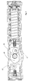
- Figure 1 shows a schematic view in lengthwise section, taken on the horizontal plane, of the door closer according to the invention on the whole;
- Figure 2 shows a schematic view of the door closer according to the invention, represented in lengthwise section, taken on the vertical plane;
- Figure 3 shows a schematic view of the door closer according to the invention in a possible variant, represented in lengthwise section, taken on the horizontal plane;
- Figure 4 shows a schematic view of the door closer according to the invention in a possible variant, represented in lengthwise section, taken on the vertical plane;
- - Figure 5 shows a schematic view of a possible variant of the door closer in which the rollers are off-centre.
- With reference to the accompanying drawings,
number 1 denotes a door closer according to the present invention on the whole. In Figures 1 and 2, the door closer is represented in a sectional way. - The door closer 1 consists basically of a containing
body 2. - The
body 2 contains movable components which cause the opening and/or closing of the door and/or arm of the door closer, the arm of the door closer being mounted on asquare pivot 3. - In the inside of the cylindrical
hollow body 2 there is afirst piston 4, connected with asecond piston 6 through a plate 5, thesecond piston 6 being coaxial and specular to thefirst piston 4. - The
second piston 6 is arranged in contrast with aspring 7 which maintains a pushing condition between twoouter covers - The plate 5 is connected with both pistons in that it engages
pins 10 in the inside of the pistons. - The
pins 10 act also as pivots for the support and rotation ofrollers - More precisely, from the version represented in Figure 1 it can be noted that the inside of the
first piston 4 and thesecond piston 6 include capsules 4' and 6' . - The capsules 4' and 6' are fixed in the piston heads by means of
valve screws 15 and therefore, the valve screws are not only components through which the oily fluid passes, but they are also elements for blocking the capsules inside the pistons. - The presence of the capsules 4' and 6' avoids the necessity of engaging
pins 10 throughpistons pins 10 to come in touch with the slide chamber and to cause possible scratches as it occurred in the known solutions. -
Rollers cam 13 from which thesquare pivot 3 goes out transversally, thesquare pivot 3 being arranged onsuited ball bearings 14. - The above-described components remain immersed in an oil bath which passes through
valve holes 15. - It is to be noted that the
cam 13 shows a particular "hearth" shape so as to give the rotation of thepivot 3 ending positions in elastic contrast in the dead point as well as intermediate pushing positions. - It is also to be noted that both opposite borders, which form the hearth cam, are not exactly symmetric and specular for the more projecting side causes a wider displacement of the pushing unit and consequently, a higher adjusting of the movement.
- This is possible for only the more projecting side of the cam works while the other side acts only as a guide.
- Advantageously, it is conceived that the pair of
rollers cam 13 so as to allow an increase in the pushing strength of the door closing device, for instance in case of heavy doors, for which more strength is needed in the closing phase. - According to variants as represented in Figures 3 and 4, the two pistons are connected through a particularly
shaped body 16 while in the preceding solution the pistons were connected through an essentially flat plate. - In this case it is still possible to use pins which are not provided with surfaces projecting on the piston outer surfaces and therefore, the slide is perfect and the chamber can not be scratched.
- A technician of this field can modify the so-described and represented aerial door closer, given as an example that does not restrict the invention, with some variants referring to means that are technically equivalent to the described ones so as to obtain solutions to be considered included in the scope of protection of the invention as defined in the following claims.
Claims (7)
- Aerial door closer provided with improved means of rotation and including a body (2) in the inside of which a cylindrical space is obtained in which a piston runs in contrast with a spring (7) and interacts with a cam (13) which is fixed to the door closing pivot (3) and/or to the panthograph arm thereof, characterized in that the said piston, which is in contrast with a spring, is divided in two semi-parts (4, 6) which are connected with each other though a plate (5) and/or other similar means and in that the said two semi-parts (4, 6) support in their inside two rollers (11, 12) which are connected and opposite each other in respect to the central cam on which the door closing pivot acts, which rollers are kept by means of pins which are fixed in the inside of the two pistons by means of a pawl or the like.
- Aerial door closer provided with improved means of rotation as claimed in claim 1, characterized in that the components that are arranged in sequence in the inside of the cylindrical hollow of the body (2) are a first piston (4) and a second piston (6), the former being connected through the plate (5) with the latter, and the second piston (6) being coaxial and specular to the first piston (4).
- Aerial door closer provided with improved means of rotation as claimed in the foregoing claims, characterized in that the said second piston (6) is put in contrast with a spring (7), which spring keeps the device in a pushing condition between two outer covers (8, 9).
- Aerial door closer provided with improved means of rotation as claimed in the foregoing claims, characterized in that the said plate (5) is connected with the two pistons and engages their insides with pins (10) which act also as pivots for the support and rotation of rollers (11, 12).
- Aerial door closer provided with improved means of rotation as claimed in the foregoing claims, characterized in that the said first piston (4) and the said second piston (6) include capsules (4', 6'), which are fixed in the piston heads by means of valve screws (15), which screws are not only components through which the oily fluid passes, but they are also elements for blocking the capsules inside the pistons.
- Aerial door closer provided with improved means of rotation as claimed in the foregoing claims, characterized in that the said rollers (11, 12) contain two opposite sides of a cam (13) from which the square pivot (3) goes out transversally, the square pivot (3) being arranged on suited ball bearings (14).
- Aerial door closer provided with improved means of rotation as claimed in the foregoing claims, characterized in that the pair of rollers (11, 12) is positioned off-axis in respect to the centre of the cam (13) so as to allow an increase in the pushing strength of the door closing device, for instance in case of heavy doors for which more strength is needed in the closing phase.
Applications Claiming Priority (2)
| Application Number | Priority Date | Filing Date | Title |
|---|---|---|---|
| ITVR20000011 IT251019Y1 (en) | 2000-03-13 | 2000-03-13 | AIR DOOR CLOSER PROVIDED WITH PERFECT ROTATION VEHICLES. |
| ITVR000011U | 2000-03-13 |
Publications (1)
| Publication Number | Publication Date |
|---|---|
| EP1134349A2 true EP1134349A2 (en) | 2001-09-19 |
Family
ID=11461767
Family Applications (1)
| Application Number | Title | Priority Date | Filing Date |
|---|---|---|---|
| EP20010105916 Withdrawn EP1134349A2 (en) | 2000-03-13 | 2001-03-09 | Overhead door closer with improved means of rotation |
Country Status (2)
| Country | Link |
|---|---|
| EP (1) | EP1134349A2 (en) |
| IT (1) | IT251019Y1 (en) |
Cited By (17)
| Publication number | Priority date | Publication date | Assignee | Title |
|---|---|---|---|---|
| WO2005098185A1 (en) * | 2004-04-12 | 2005-10-20 | Soprano Eletrometalúrgica E Hidráulica | Door closing device and resulting device assembly process |
| DE102004061627A1 (en) * | 2004-12-17 | 2006-07-06 | Dorma Gmbh + Co. Kg | door closers |
| GB2433296A (en) * | 2005-12-12 | 2007-06-20 | Levasseur Systems Sa | Door operator comprising resilient actuator and damping means operated by separate cams |
| GB2462633A (en) * | 2008-08-14 | 2010-02-17 | Jebron Ltd | A roller cam follower mounted within a rotatable carrier |
| US20100064472A1 (en) * | 2007-01-12 | 2010-03-18 | Dorma Gmbh + Co.Kg | Door Closer |
| KR101028990B1 (en) | 2008-05-08 | 2011-04-13 | 이덕환 | Door closer |
| US8225458B1 (en) | 2001-07-13 | 2012-07-24 | Hoffberg Steven M | Intelligent door restraint |
| CN102971476A (en) * | 2010-07-07 | 2013-03-13 | 多玛两合有限公司 | Door closer or door drive |
| DE202012003928U1 (en) | 2012-04-18 | 2013-07-22 | Gretsch-Unitas Gmbh | door closers |
| CN103233640A (en) * | 2013-04-18 | 2013-08-07 | 赵泳淇 | Built-in floor spring |
| CN103850562A (en) * | 2012-11-28 | 2014-06-11 | 多玛两合有限公司 | Door actuator |
| CN103850560A (en) * | 2012-11-28 | 2014-06-11 | 多玛两合有限公司 | Door actuator |
| DE102013205206A1 (en) * | 2013-03-25 | 2014-09-25 | Geze Gmbh | Feeding device for a wing of a door or a window |
| CN105672799A (en) * | 2014-12-05 | 2016-06-15 | 多玛德国有限公司 | Floor spring |
| US20160177610A1 (en) * | 2014-12-17 | 2016-06-23 | Dorma Deutschland Gmbh | Door operator |
| EP2746508B1 (en) | 2010-09-06 | 2018-09-12 | In & Tec S.r.l. | Door closing hinge, particularly for glass doors |
| EP3885519A1 (en) * | 2020-03-27 | 2021-09-29 | Gretsch-Unitas GmbH Baubeschläge | Device for closing a door or window leaf |
-
2000
- 2000-03-13 IT ITVR20000011 patent/IT251019Y1/en active
-
2001
- 2001-03-09 EP EP20010105916 patent/EP1134349A2/en not_active Withdrawn
Cited By (33)
| Publication number | Priority date | Publication date | Assignee | Title |
|---|---|---|---|---|
| US8225458B1 (en) | 2001-07-13 | 2012-07-24 | Hoffberg Steven M | Intelligent door restraint |
| US9121217B1 (en) | 2001-07-13 | 2015-09-01 | Steven M. Hoffberg | Intelligent door restraint |
| US9045927B1 (en) | 2001-07-13 | 2015-06-02 | Steven M. Hoffberg | Intelligent door restraint |
| US9995076B1 (en) | 2001-07-13 | 2018-06-12 | Steven M. Hoffberg | Intelligent door restraint |
| WO2005098185A1 (en) * | 2004-04-12 | 2005-10-20 | Soprano Eletrometalúrgica E Hidráulica | Door closing device and resulting device assembly process |
| DE102004061627A1 (en) * | 2004-12-17 | 2006-07-06 | Dorma Gmbh + Co. Kg | door closers |
| DE102004061627B4 (en) * | 2004-12-17 | 2007-02-01 | Dorma Gmbh + Co. Kg | door closers |
| GB2433296B (en) * | 2005-12-12 | 2008-02-20 | Levasseur Systems Sa | Device for opening and closing a leaf of a swing type door |
| GB2433296A (en) * | 2005-12-12 | 2007-06-20 | Levasseur Systems Sa | Door operator comprising resilient actuator and damping means operated by separate cams |
| US8732904B2 (en) * | 2007-01-12 | 2014-05-27 | Dorma Gmbh + Co. Kg | Door closer |
| US20100064472A1 (en) * | 2007-01-12 | 2010-03-18 | Dorma Gmbh + Co.Kg | Door Closer |
| DE102007002651B4 (en) * | 2007-01-12 | 2015-04-30 | Dorma Deutschland Gmbh | door closers |
| KR101028990B1 (en) | 2008-05-08 | 2011-04-13 | 이덕환 | Door closer |
| GB2462633B (en) * | 2008-08-14 | 2013-01-02 | Jebron Ltd | Door closer |
| GB2462633A (en) * | 2008-08-14 | 2010-02-17 | Jebron Ltd | A roller cam follower mounted within a rotatable carrier |
| CN102971476A (en) * | 2010-07-07 | 2013-03-13 | 多玛两合有限公司 | Door closer or door drive |
| EP2746508B1 (en) | 2010-09-06 | 2018-09-12 | In & Tec S.r.l. | Door closing hinge, particularly for glass doors |
| DE202012003928U1 (en) | 2012-04-18 | 2013-07-22 | Gretsch-Unitas Gmbh | door closers |
| WO2013156094A1 (en) | 2012-04-18 | 2013-10-24 | Gretsch-Unitas GmbH Baubeschläge | Door closer |
| CN103850560A (en) * | 2012-11-28 | 2014-06-11 | 多玛两合有限公司 | Door actuator |
| CN103850562B (en) * | 2012-11-28 | 2017-12-15 | 多玛两合有限公司 | Door executor |
| CN103850562A (en) * | 2012-11-28 | 2014-06-11 | 多玛两合有限公司 | Door actuator |
| CN103850560B (en) * | 2012-11-28 | 2017-12-15 | 多玛两合有限公司 | Door operators |
| EP2738334A3 (en) * | 2012-11-28 | 2017-08-09 | dormakaba Deutschland GmbH | Door closer |
| EP2738333A3 (en) * | 2012-11-28 | 2017-08-09 | dormakaba Deutschland GmbH | Door closer |
| DE102013205206A1 (en) * | 2013-03-25 | 2014-09-25 | Geze Gmbh | Feeding device for a wing of a door or a window |
| DE102013205206B4 (en) * | 2013-03-25 | 2015-12-31 | Geze Gmbh | Feeding device for a wing of a door or a window |
| CN103233640B (en) * | 2013-04-18 | 2016-04-27 | 赵泳淇 | Built-in floor spring |
| CN103233640A (en) * | 2013-04-18 | 2013-08-07 | 赵泳淇 | Built-in floor spring |
| CN105672799A (en) * | 2014-12-05 | 2016-06-15 | 多玛德国有限公司 | Floor spring |
| US20160177610A1 (en) * | 2014-12-17 | 2016-06-23 | Dorma Deutschland Gmbh | Door operator |
| US9790723B2 (en) * | 2014-12-17 | 2017-10-17 | Dorma Deutschland Gmbh | Door operator |
| EP3885519A1 (en) * | 2020-03-27 | 2021-09-29 | Gretsch-Unitas GmbH Baubeschläge | Device for closing a door or window leaf |
Also Published As
| Publication number | Publication date |
|---|---|
| IT251019Y1 (en) | 2003-11-04 |
| ITVR20000011U1 (en) | 2001-09-13 |
Similar Documents
| Publication | Publication Date | Title |
|---|---|---|
| EP1134349A2 (en) | Overhead door closer with improved means of rotation | |
| US6154924A (en) | Door closer unit | |
| WO2013115458A1 (en) | Single hinge damping device for doors of home appliances | |
| KR20070014713A (en) | Hinge apparatus having automatic return function | |
| JP6815018B2 (en) | Guide device for sliding doors | |
| WO2006025663A1 (en) | Slim type hinge apparatus having automatic return function | |
| EP3309336A1 (en) | Snap hinge with damped closing | |
| SK11012001A3 (en) | Sliding panel comprising several wall elements that can be displaced laterally | |
| JP2005146625A (en) | Hinge device | |
| CN215889720U (en) | Hinge and refrigeration equipment with same | |
| EP2781676B1 (en) | Concealed hinge with an automatic return device toward a closed position | |
| US6094866A (en) | System for opening and closing doors in furniture, rooms and the like | |
| KR101661081B1 (en) | A Self-Closing Device for Sliding Door capable of multi-direction rotation | |
| EP2472036A2 (en) | Hydraulic mechanism for door opening | |
| EP3612699B1 (en) | Mechanism for moving a furniture door | |
| EP3179023A1 (en) | A hinge mechanism | |
| JP2758933B2 (en) | Door closer | |
| JP2546493Y2 (en) | Hanging cabinet | |
| EP1523929B1 (en) | Balancing device for a door of an household appliance | |
| CN210918807U (en) | Wine cabinet sealing structure | |
| US4913215A (en) | Bendable multiple window | |
| JP2003004115A5 (en) | ||
| CN210918618U (en) | Hinge assembly of hardware | |
| KR200394864Y1 (en) | The door stopper | |
| ITMI20082001A1 (en) | DEVICE FOR VERTICAL HANDLING OF FURNITURE DOORS. |
Legal Events
| Date | Code | Title | Description |
|---|---|---|---|
| PUAI | Public reference made under article 153(3) epc to a published international application that has entered the european phase |
Free format text: ORIGINAL CODE: 0009012 |
|
| AK | Designated contracting states |
Kind code of ref document: A2 Designated state(s): AT BE CH CY DE DK ES FI FR GB GR IE IT LI LU MC NL PT SE TR |
|
| AX | Request for extension of the european patent |
Free format text: AL;LT;LV;MK;RO;SI |
|
| STAA | Information on the status of an ep patent application or granted ep patent |
Free format text: STATUS: THE APPLICATION IS DEEMED TO BE WITHDRAWN |
|
| 18D | Application deemed to be withdrawn |
Effective date: 20031001 |