EP1132652B1 - Hydrodynamic torque converter including overrunning clutch and stator - Google Patents
Hydrodynamic torque converter including overrunning clutch and stator Download PDFInfo
- Publication number
- EP1132652B1 EP1132652B1 EP01105799A EP01105799A EP1132652B1 EP 1132652 B1 EP1132652 B1 EP 1132652B1 EP 01105799 A EP01105799 A EP 01105799A EP 01105799 A EP01105799 A EP 01105799A EP 1132652 B1 EP1132652 B1 EP 1132652B1
- Authority
- EP
- European Patent Office
- Prior art keywords
- overrunning clutch
- outer ring
- stator
- assembly
- sub
- Prior art date
- Legal status (The legal status is an assumption and is not a legal conclusion. Google has not performed a legal analysis and makes no representation as to the accuracy of the status listed.)
- Expired - Lifetime
Links
- 239000000463 material Substances 0.000 claims description 11
- 238000002347 injection Methods 0.000 claims description 7
- 239000007924 injection Substances 0.000 claims description 7
- XAGFODPZIPBFFR-UHFFFAOYSA-N aluminium Chemical compound [Al] XAGFODPZIPBFFR-UHFFFAOYSA-N 0.000 claims description 5
- 229910052782 aluminium Inorganic materials 0.000 claims description 5
- 238000000034 method Methods 0.000 claims description 4
- 239000004033 plastic Substances 0.000 claims description 3
- 229920003023 plastic Polymers 0.000 claims description 3
- 229910000831 Steel Inorganic materials 0.000 claims description 2
- 239000011152 fibreglass Substances 0.000 claims description 2
- 230000000717 retained effect Effects 0.000 claims description 2
- 229920006114 semi-crystalline semi-aromatic polyamide Polymers 0.000 claims description 2
- 239000010959 steel Substances 0.000 claims description 2
- 229910000838 Al alloy Inorganic materials 0.000 claims 1
- 230000003247 decreasing effect Effects 0.000 description 4
- 238000005516 engineering process Methods 0.000 description 2
- 238000003754 machining Methods 0.000 description 2
- 238000004519 manufacturing process Methods 0.000 description 2
- 229910000906 Bronze Inorganic materials 0.000 description 1
- 239000000956 alloy Substances 0.000 description 1
- 229910045601 alloy Inorganic materials 0.000 description 1
- 239000010974 bronze Substances 0.000 description 1
- 238000006243 chemical reaction Methods 0.000 description 1
- 238000001816 cooling Methods 0.000 description 1
- KUNSUQLRTQLHQQ-UHFFFAOYSA-N copper tin Chemical compound [Cu].[Sn] KUNSUQLRTQLHQQ-UHFFFAOYSA-N 0.000 description 1
- 230000007812 deficiency Effects 0.000 description 1
- 230000003292 diminished effect Effects 0.000 description 1
- 230000000694 effects Effects 0.000 description 1
- 238000001746 injection moulding Methods 0.000 description 1
- 230000010354 integration Effects 0.000 description 1
- 238000000465 moulding Methods 0.000 description 1
Images



Classifications
-
- F—MECHANICAL ENGINEERING; LIGHTING; HEATING; WEAPONS; BLASTING
- F16—ENGINEERING ELEMENTS AND UNITS; GENERAL MEASURES FOR PRODUCING AND MAINTAINING EFFECTIVE FUNCTIONING OF MACHINES OR INSTALLATIONS; THERMAL INSULATION IN GENERAL
- F16H—GEARING
- F16H45/00—Combinations of fluid gearings for conveying rotary motion with couplings or clutches
- F16H45/02—Combinations of fluid gearings for conveying rotary motion with couplings or clutches with mechanical clutches for bridging a fluid gearing of the hydrokinetic type
-
- F—MECHANICAL ENGINEERING; LIGHTING; HEATING; WEAPONS; BLASTING
- F16—ENGINEERING ELEMENTS AND UNITS; GENERAL MEASURES FOR PRODUCING AND MAINTAINING EFFECTIVE FUNCTIONING OF MACHINES OR INSTALLATIONS; THERMAL INSULATION IN GENERAL
- F16H—GEARING
- F16H41/00—Rotary fluid gearing of the hydrokinetic type
- F16H41/24—Details
-
- F—MECHANICAL ENGINEERING; LIGHTING; HEATING; WEAPONS; BLASTING
- F16—ENGINEERING ELEMENTS AND UNITS; GENERAL MEASURES FOR PRODUCING AND MAINTAINING EFFECTIVE FUNCTIONING OF MACHINES OR INSTALLATIONS; THERMAL INSULATION IN GENERAL
- F16H—GEARING
- F16H41/00—Rotary fluid gearing of the hydrokinetic type
- F16H41/24—Details
- F16H2041/246—Details relating to one way clutch of the stator
Definitions
- the invention concerns a sub-assembly of a hydrodynamic converter, comprising an overrunning clutch, a stator, and thrust bearings according the preamble of claim 1 which is known from US-A-5 094 076.
- a hydrodynamic converter is provided with at least one overrunning clutch.
- the overrunning clutch is associated with the stator of such a converter.
- stators of hydrodynamic converters from injection molded aluminum and to structurally combine them with the overrunning clutch.
- the overrunning clutch outer ring is structurally interlocked with the stator.
- the overrunning clutch outer ring must be hardened and its surface must be machined with very exacting tolerances.
- the invention is based on the task of creating an assembly of the above-mentioned type in such a manner that the manufacturing costs are decreased, the number of components is diminished, and so that the assembly is easier to work with.
- the entire machined overrunning clutch outer ring is integrated in the stator, in that it is formed by injecting the mentioned material around the overrunning clutch outer ring. Refinishing the overrunning clutch outer ring is not necessary when using the above-mentioned materials, since the injection temperatures do not need to be so high that the effect of the hardening of the outer ring is lost again. In contrast, refinishing is necessary in every case when the stator is made of aluminum, since the injection temperatures are significantly higher.
- the stator is mounted radially on the overrunning clutch outer ring towards the overrunning clutch inner ring using two U-shaped disks of bronze coated sheet steel.
- the assembly additionally has two thrust bearings.
- the one bearing receives a relatively high axial load in the torque conversion process. Therefore, for functional reasons, this bearing is a needle bearing.
- the needle bearing can be in form-fitting or force-fitting engagement with the stator.
- the overrunning clutch is axially retained by the slide bearing of the needle bearing.
- the other bearing, located on the opposite side of the assembly, is less stressed. It can be implemented as a slide bearing, and is therefore a component of the injection molded part, and therefore of the stator. Through design configuration, the stator assembly can be implemented as a self contained, pre-assembled unit without loose individual parts.
- the assembly can be manufactured more cost-effectively, since machining of the overrunning outer ring is no longer necessary after integration in the stator.
- the cost of the stator is reduced by the selection of the plastic material, in comparison to those made according to conventional technology. In comparison to common executions, the weight is significantly decreased with aluminum.
- the complexity of the stator assembly is reduced in comparison to the conventional technology.
- the assembly can be delivered and assembled as a self-contained unit without individual pieces.
- the assembly includes an overrunning clutch 1.
- This comprises an inner cage 1.1, an outer cage 1.5, numerous sprags 1.2, two bearing rings 1.6, an overrunning clutch inner ring 1.3 and an overrunning clutch outer ring 1.4.
- the overrunning clutch outer ring has an outer contour which deviates from a cylindrical shape.
- the overrunning clutch inner ring is part of a shaft, as depicted. However, it can also be executed as a separate part, torsionally fixed with such a shaft.
- Stator 2 of the torque converter which is completely made of plastic material, comprises a ring 2.1 with a collar of blades 2.2.
- This ring 2.1 is interlocked with the non-cylindrical contour of the overrunning clutch outer ring 1.4 by injecting molding around the overrunning clutch outer ring. A torsionally fixed connection is insured through this interlocking. At the same time the overrunning clutch outer ring is thereby prevented from axially drifting relative to the stator.
- the interlocking connection of the axial needle bearing 4.2 to the stator 2 is realized by the design of ring 2.1.
- the design described here achieves very exact centering of all critical components.
- one slide bearing 4.1 is located on the side of the assembly that receives hydraulic flow. This is a unitary part with the stator 2. Therefore, it is manufactured with the rest of the stator 2 during injection molding. See segment 4.1.1 with the groove located in between, in which oil flows during operation for cooling purposes.
- Bearing rings 1.6 have bores 5.1, through which oil flows in order to lubricate overrunning clutch 1.
- the figures refer to a sprag clutch. However, the invention is also applicable to other overrunning clutch types, for example one way roller clutches or ratchet clutches.
Landscapes
- Engineering & Computer Science (AREA)
- General Engineering & Computer Science (AREA)
- Mechanical Engineering (AREA)
- Rolling Contact Bearings (AREA)
- Injection Moulding Of Plastics Or The Like (AREA)
- Mechanical Operated Clutches (AREA)
Description
- The invention concerns a sub-assembly of a hydrodynamic converter, comprising an overrunning clutch, a stator, and thrust bearings according the preamble of
claim 1 which is known from US-A-5 094 076. - Many devices are known, in which a hydrodynamic converter is provided with at least one overrunning clutch. The overrunning clutch is associated with the stator of such a converter. Reference may be made to DE 36 04 393 C2 by way of example.
- In the automobile industry here is a constant demand for decreasing the weight of components as well as component space. At the same, there is a striving for decreasing costs, as well as simplifying and streamlining operations, especially for assembly and disassembly of such components.
- It is common to manufacture stators of hydrodynamic converters from injection molded aluminum and to structurally combine them with the overrunning clutch. In this case, the overrunning clutch outer ring is structurally interlocked with the stator. The overrunning clutch outer ring must be hardened and its surface must be machined with very exacting tolerances.
- This common form of assembly has many disadvantages. Machining the overrunning clutch outer ring that is integrated in the stator is time-consuming and expensive. The weight of the assembly is not yet optimal, despite use of aluminum as an alloy. The deficiency leaves much to be desired.
- The invention is based on the task of creating an assembly of the above-mentioned type in such a manner that the manufacturing costs are decreased, the number of components is diminished, and so that the assembly is easier to work with.
- This task is accomplished by the characteristics of
Claim 1. In accordance therewith the inventors chose a material for the stator of a hydrodynamic converter that has the necessary sturdiness, toughness and heat resistance: namely glass fiber reinforced plastic. For this they preferred a semi-crystalline polyamide with a temperature resistance of 170° C or more, and a peak temperature resistance of 200° or more. - The entire machined overrunning clutch outer ring is integrated in the stator, in that it is formed by injecting the mentioned material around the overrunning clutch outer ring. Refinishing the overrunning clutch outer ring is not necessary when using the above-mentioned materials, since the injection temperatures do not need to be so high that the effect of the hardening of the outer ring is lost again. In contrast, refinishing is necessary in every case when the stator is made of aluminum, since the injection temperatures are significantly higher.
- The material mentioned also holds up to the mechanical demands. It proved to be excellent for transferring considerable torque.
- The stator is mounted radially on the overrunning clutch outer ring towards the overrunning clutch inner ring using two U-shaped disks of bronze coated sheet steel. The assembly additionally has two thrust bearings. The one bearing receives a relatively high axial load in the torque conversion process. Therefore, for functional reasons, this bearing is a needle bearing. The needle bearing can be in form-fitting or force-fitting engagement with the stator. At the same time, the overrunning clutch is axially retained by the slide bearing of the needle bearing. The other bearing, located on the opposite side of the assembly, is less stressed. It can be implemented as a slide bearing, and is therefore a component of the injection molded part, and therefore of the stator. Through design configuration, the stator assembly can be implemented as a self contained, pre-assembled unit without loose individual parts.
- Important benefits are as follows:
- The assembly can be manufactured more cost-effectively, since machining of the overrunning outer ring is no longer necessary after integration in the stator. The cost of the stator is reduced by the selection of the plastic material, in comparison to those made according to conventional technology. In comparison to common executions, the weight is significantly decreased with aluminum. The complexity of the stator assembly is reduced in comparison to the conventional technology. The assembly can be delivered and assembled as a self-contained unit without individual pieces.
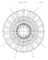
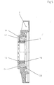
- The invention is further explained in the figures. The following details are represented:
- Figure 1
- shows an assembly in axial section, based on the invention.
- Figure 2
- shows the assembly of Figure 1 in a cross section along section line II - I.
- Figure 3
- shows the object from Figure 1 viewed from above in direction of arrow A.
- Figure 4
- shows the object from Figure 1 viewed from above in direction of arrow B.
- Figure 5
- shows the object from Figure 1 without inner ring 1.3, without needle bearing 4.2.
- The assembly includes an
overrunning clutch 1. This comprises an inner cage 1.1, an outer cage 1.5, numerous sprags 1.2, two bearing rings 1.6, an overrunning clutch inner ring 1.3 and an overrunning clutch outer ring 1.4. The overrunning clutch outer ring has an outer contour which deviates from a cylindrical shape. The overrunning clutch inner ring is part of a shaft, as depicted. However, it can also be executed as a separate part, torsionally fixed with such a shaft.
Stator 2 of the torque converter, which is completely made of plastic material, comprises a ring 2.1 with a collar of blades 2.2. This ring 2.1 is interlocked with the non-cylindrical contour of the overrunning clutch outer ring 1.4 by injecting molding around the overrunning clutch outer ring. A torsionally fixed connection is insured through this interlocking. At the same time the overrunning clutch outer ring is thereby prevented from axially drifting relative to the stator. - The interlocking connection of the axial needle bearing 4.2 to the
stator 2 is realized by the design of ring 2.1. The design described here achieves very exact centering of all critical components. - As figures 1 and 4 show, one slide bearing 4.1 is located on the side of the assembly that receives hydraulic flow. This is a unitary part with the
stator 2. Therefore, it is manufactured with the rest of thestator 2 during injection molding. See segment 4.1.1 with the groove located in between, in which oil flows during operation for cooling purposes. - Bearing rings 1.6 have bores 5.1, through which oil flows in order to lubricate overrunning
clutch 1. - Instead of the embodiment described here, it is also possible to inject ring 2.1 around the needle bearing 4.2 during the injection process, so that in this manner it becomes a fixed component of the assembly.
- The figures refer to a sprag clutch. However, the invention is also applicable to other overrunning clutch types, for example one way roller clutches or ratchet clutches.
Claims (11)
- Sub-assembly of a hydrodynamic converter, comprising:an overrunning clutch (1) includingan overrunning clutch inner ring (1.3),an overrunning clutch outer ring (1.4) having first and second axial surfaces, anda bearing unit provided between said inner and outer ring and including bearings or sprags,a stator 82); andtwo thrust bearings (4.1, 4.2) axially bracketing the overrunning clutch outer ring (1.4),wherein the stator (2) consists of glass reinforced plastic and is manufactured in an injection process during which the stator (2) is injected directly onto the overrunning clutch outer ring (1.4), forming an engaging U shape when viewed in axial section, characterised in that the stator (2) is mounted radially on the overrunning clutch outer ring (1.4) towards the overrunning clutch inner ring (1.3) via two bearing rings (1.6) in form of U-shaped disks the bearings or sprags are positioned relative to each other by an inner cage (1.1) and an outer cage (1.5), and are axially positioned and retained between the two bearing rings (1.6)
wherein the material (2.4), which encloses the overrunning clutch outer ring (1.4) on the one axial side, extends radially inwardly to the area of one overrunning clutch bearing ring (1.6); and
wherein the material (2.3) enclosing the overrunning clutch outer ring (1.4) on the other axial side extends radially inwardly to the area of the overrunning clutch outer ring (1.4). - Sub-assembly as in claim 1, wherein the thrust bearing (4.1) which is on the side of the stator (2) which is acted upon hydraulically is a slide bearing formed unitarily with the stator (2).
- Sub-assembly as in claim 1, wherein the bearing (4.1) which is on the side of the stator (2) which is acted upon hydraulically is a slide bearing torsionally fixed with the stator (2).
- Sub-assembly as in claim 1, wherein the bearing (4.2) opposite the side of the stator (2) which is acted upon hydraulically is a needle bearing.
- Sub-assembly as in claim 1,
wherein the material (2.3) covering the overrunning clutch outer ring (1.4) on the one side, which extends radially inwardly into to the area of the overrunning clutch outer ring (1.3) is on the side of the stator (2) which is acted upon hydraulically,
wherein the material (2.3) enclosing the overrunning clutch outer ring (1.4) on the one axial side includes - seen from above - a number of projections (2.3.1), between which there are grooves, and
wherein the projections (2.3.1) extend radially inwardly as far as the outer ring (1.4) of the overrunning clutch (1.1), and only partially cover its axial surface. - Sub-assembly as in claim 1, wherein two additional steel disks (5) are arranged for housing the needle bearing (4.2).
- Sub-assembly as in claim 4, wherein the needle bearing (4.2) is in position during the injection process, and is therefore enclosed by the material (2.3) enclosing the overrunning clutch outer ring (1.4) on the one front side.
- Sub-assembly as in claim 1, wherein the outer ring (1.4) of the overrunning clutch 1 is manufactured structurally interlocked with the stator (2).
- Sub-assembly as in claim 1, wherein the outer circumference of outer ring (1.4) of the overrunning clutch 1 is non-cylindrical.
- Sub-assembly as in claim 1, wherein the plastic is a semi-crystalline polyamide.
- Sub-assembly as in claim 1, wherein the overrunning clutch outer ring is formed of aluminum or an aluminum alloy.
Applications Claiming Priority (2)
| Application Number | Priority Date | Filing Date | Title |
|---|---|---|---|
| DE10011237A DE10011237C2 (en) | 2000-03-08 | 2000-03-08 | Assembly with freewheel and stator of a hydrodynamic converter |
| DE10011237 | 2000-03-08 |
Publications (3)
| Publication Number | Publication Date |
|---|---|
| EP1132652A2 EP1132652A2 (en) | 2001-09-12 |
| EP1132652A3 EP1132652A3 (en) | 2004-05-06 |
| EP1132652B1 true EP1132652B1 (en) | 2007-05-09 |
Family
ID=7633939
Family Applications (1)
| Application Number | Title | Priority Date | Filing Date |
|---|---|---|---|
| EP01105799A Expired - Lifetime EP1132652B1 (en) | 2000-03-08 | 2001-03-08 | Hydrodynamic torque converter including overrunning clutch and stator |
Country Status (5)
| Country | Link |
|---|---|
| US (1) | US6481549B2 (en) |
| EP (1) | EP1132652B1 (en) |
| JP (1) | JP4610761B2 (en) |
| KR (1) | KR100728357B1 (en) |
| DE (2) | DE10011237C2 (en) |
Families Citing this family (5)
| Publication number | Priority date | Publication date | Assignee | Title |
|---|---|---|---|---|
| FR2830917B1 (en) * | 2001-10-11 | 2004-01-23 | Dype Plastique | REACTOR FOR TORQUE CONVERTER AND MANUFACTURING METHOD THEREOF |
| US6902046B1 (en) | 2002-03-21 | 2005-06-07 | Sonnax Industries, Inc. | High performance sprag clutch assembly |
| DE10231608A1 (en) * | 2002-07-12 | 2004-01-29 | Daimlerchrysler Ag | Hydrodynamic torque converter with a stator and manufacturing method for such |
| TWI686297B (en) | 2014-08-06 | 2020-03-01 | 日商住友金屬礦山股份有限公司 | Heat ray shielding film, heat ray shielding interlayer transparent substrate, automobile, building |
| KR101582486B1 (en) | 2014-10-10 | 2016-01-05 | 정찬용 | The fluid clutch using differential gear |
Family Cites Families (20)
| Publication number | Priority date | Publication date | Assignee | Title |
|---|---|---|---|---|
| JPH0697065B2 (en) * | 1985-02-12 | 1994-11-30 | 株式会社大金製作所 | Automatic transmission |
| JPS63231921A (en) * | 1987-03-20 | 1988-09-28 | Nok Corp | Manufacture of stator |
| JPH02125153A (en) * | 1988-11-01 | 1990-05-14 | Aisin Aw Co Ltd | Torque converter |
| US5125487A (en) * | 1990-08-31 | 1992-06-30 | Ina Bearing Company, Inc. | Method and apparatus for providing torque converter having improved stator/clutch assembly |
| US5094076A (en) * | 1990-11-16 | 1992-03-10 | Maclean-Fogg Company | Torque converter reactor assembly and method |
| JP2588612Y2 (en) * | 1991-02-12 | 1999-01-13 | エヌオーケー株式会社 | Stator |
| JP3155776B2 (en) * | 1991-07-23 | 2001-04-16 | 松下電工株式会社 | Stator for bearing rotation |
| DE4336386A1 (en) * | 1993-10-26 | 1995-04-27 | Bosch Gmbh Robert | Turbine wheel and/or pump wheel (impeller) |
| JPH07167169A (en) * | 1993-12-17 | 1995-07-04 | Nsk Warner Kk | Outer ring fixing structure for one-way clutch |
| US5431536A (en) * | 1994-02-01 | 1995-07-11 | General Motors Corporation | Molded torque converter stator and integral race for a one-way torque transmitter |
| JP3204854B2 (en) * | 1994-09-13 | 2001-09-04 | 株式会社エクセディ | Wheel stator assembly |
| US5632363A (en) * | 1995-04-21 | 1997-05-27 | Koyo Seiko Co., Ltd. | One-way clutch |
| EP0770796B1 (en) * | 1995-10-27 | 2000-04-12 | Koyo Seiko Co., Ltd. | One-way clutch |
| JPH09126296A (en) * | 1995-10-27 | 1997-05-13 | Koyo Seiko Co Ltd | One-way clutch |
| DE19626974A1 (en) * | 1996-04-20 | 1997-10-23 | Ford Werke Ag | Composite component |
| EP0802037B1 (en) | 1996-04-20 | 2001-10-10 | Georg Fischer Mössner GmbH | Composite article |
| JP3534543B2 (en) * | 1996-07-10 | 2004-06-07 | 株式会社エクセディ | Turkish converter stator |
| JP3943629B2 (en) * | 1996-10-15 | 2007-07-11 | 松下電工株式会社 | Wheel stator for automatic transmission |
| DE19736874A1 (en) * | 1997-08-26 | 1999-03-11 | Mannesmann Sachs Ag | Injection molded guide wheel for torque converter |
| JP3939840B2 (en) * | 1997-11-18 | 2007-07-04 | ジヤトコ株式会社 | Torque converter |
-
2000
- 2000-03-08 DE DE10011237A patent/DE10011237C2/en not_active Expired - Fee Related
-
2001
- 2001-03-08 DE DE60128280T patent/DE60128280T2/en not_active Expired - Lifetime
- 2001-03-08 US US09/801,462 patent/US6481549B2/en not_active Expired - Fee Related
- 2001-03-08 JP JP2001064623A patent/JP4610761B2/en not_active Expired - Fee Related
- 2001-03-08 EP EP01105799A patent/EP1132652B1/en not_active Expired - Lifetime
- 2001-03-08 KR KR1020010011909A patent/KR100728357B1/en not_active Expired - Fee Related
Non-Patent Citations (1)
| Title |
|---|
| None * |
Also Published As
| Publication number | Publication date |
|---|---|
| DE60128280D1 (en) | 2007-06-21 |
| KR100728357B1 (en) | 2007-06-13 |
| JP2001295910A (en) | 2001-10-26 |
| DE10011237A1 (en) | 2001-10-04 |
| DE10011237C2 (en) | 2002-09-12 |
| JP4610761B2 (en) | 2011-01-12 |
| KR20010089202A (en) | 2001-09-29 |
| EP1132652A3 (en) | 2004-05-06 |
| US20010023805A1 (en) | 2001-09-27 |
| US6481549B2 (en) | 2002-11-19 |
| DE60128280T2 (en) | 2008-01-10 |
| EP1132652A2 (en) | 2001-09-12 |
Similar Documents
| Publication | Publication Date | Title |
|---|---|---|
| CA2321916C (en) | Overrunning coupling assembly and manufacturing method | |
| US8910764B2 (en) | Overrunning clutch with integral piloting using assembled bearing blocks | |
| KR20090027632A (en) | Shaft with fixed component | |
| CN100575746C (en) | Stator supports for torque converters | |
| US6044946A (en) | Torque converter for a vehicle | |
| US5822987A (en) | Stator and one way clutch assembly for a torque converter | |
| US6481549B2 (en) | Hydrodynamic converter including overrunning clutch and stator | |
| US5586434A (en) | One way clutch mechanism for a torque converter | |
| US6619036B2 (en) | Stator support structure for torque converter | |
| US9476452B2 (en) | Transmission thrust washer with circulation circuit | |
| US6902046B1 (en) | High performance sprag clutch assembly | |
| US8881393B2 (en) | Manufacturing method of impeller for fluid transmitting device | |
| US20020011385A1 (en) | One-way clutch supporting structure | |
| CZ303298A3 (en) | Hydraulic pump | |
| JP3875771B2 (en) | One way clutch | |
| CA1188354A (en) | Axial-bearing arrangement on shafts, in particular in speed-change gears of motor vehicles | |
| CN114294344B (en) | Clutch, especially dual clutch, for a motor vehicle | |
| US20060254267A1 (en) | Hydrodynamic torque converter | |
| JP3610387B2 (en) | One-way clutch and bearing assembly | |
| EP4285032B1 (en) | A multistage centrifugal pump for pumping fluid, an impeller / shaft assembly and a method for assembling an impeller / shaft assembly | |
| JP3657646B2 (en) | One way clutch bush | |
| KR100300191B1 (en) | Hydraulic Torque Converter Stator_ | |
| US20230291282A1 (en) | Electric drive unit with rotor heat sink formed of heat sink elements | |
| JPS63246544A (en) | Bonding structure for friction element in automatic transmission with inner circumferential section of drum | |
| JP2006336771A (en) | Pulley device and manufacturing method thereof |
Legal Events
| Date | Code | Title | Description |
|---|---|---|---|
| PUAI | Public reference made under article 153(3) epc to a published international application that has entered the european phase |
Free format text: ORIGINAL CODE: 0009012 |
|
| AK | Designated contracting states |
Kind code of ref document: A2 Designated state(s): AT BE CH CY DE DK ES FI FR GB GR IE IT LI LU MC NL PT SE TR |
|
| AX | Request for extension of the european patent |
Free format text: AL;LT;LV;MK;RO;SI |
|
| PUAL | Search report despatched |
Free format text: ORIGINAL CODE: 0009013 |
|
| AK | Designated contracting states |
Kind code of ref document: A3 Designated state(s): AT BE CH CY DE DK ES FI FR GB GR IE IT LI LU MC NL PT SE TR |
|
| AX | Request for extension of the european patent |
Extension state: AL LT LV MK RO SI |
|
| 17P | Request for examination filed |
Effective date: 20040701 |
|
| 17Q | First examination report despatched |
Effective date: 20041119 |
|
| AKX | Designation fees paid |
Designated state(s): DE FR |
|
| RAP1 | Party data changed (applicant data changed or rights of an application transferred) |
Owner name: BORGWARNER INC. |
|
| GRAP | Despatch of communication of intention to grant a patent |
Free format text: ORIGINAL CODE: EPIDOSNIGR1 |
|
| GRAS | Grant fee paid |
Free format text: ORIGINAL CODE: EPIDOSNIGR3 |
|
| GRAA | (expected) grant |
Free format text: ORIGINAL CODE: 0009210 |
|
| AK | Designated contracting states |
Kind code of ref document: B1 Designated state(s): DE FR |
|
| REF | Corresponds to: |
Ref document number: 60128280 Country of ref document: DE Date of ref document: 20070621 Kind code of ref document: P |
|
| ET | Fr: translation filed | ||
| PLBE | No opposition filed within time limit |
Free format text: ORIGINAL CODE: 0009261 |
|
| STAA | Information on the status of an ep patent application or granted ep patent |
Free format text: STATUS: NO OPPOSITION FILED WITHIN TIME LIMIT |
|
| 26N | No opposition filed |
Effective date: 20080212 |
|
| REG | Reference to a national code |
Ref country code: FR Ref legal event code: PLFP Year of fee payment: 15 |
|
| PGFP | Annual fee paid to national office [announced via postgrant information from national office to epo] |
Ref country code: FR Payment date: 20150224 Year of fee payment: 15 |
|
| PGFP | Annual fee paid to national office [announced via postgrant information from national office to epo] |
Ref country code: DE Payment date: 20150331 Year of fee payment: 15 |
|
| REG | Reference to a national code |
Ref country code: DE Ref legal event code: R119 Ref document number: 60128280 Country of ref document: DE |
|
| REG | Reference to a national code |
Ref country code: FR Ref legal event code: ST Effective date: 20161130 |
|
| PG25 | Lapsed in a contracting state [announced via postgrant information from national office to epo] |
Ref country code: FR Free format text: LAPSE BECAUSE OF NON-PAYMENT OF DUE FEES Effective date: 20160331 Ref country code: DE Free format text: LAPSE BECAUSE OF NON-PAYMENT OF DUE FEES Effective date: 20161001 |