EP1132236A2 - Method and apparatus for mounting a drive mechanism within a door module - Google Patents
Method and apparatus for mounting a drive mechanism within a door module Download PDFInfo
- Publication number
- EP1132236A2 EP1132236A2 EP01302093A EP01302093A EP1132236A2 EP 1132236 A2 EP1132236 A2 EP 1132236A2 EP 01302093 A EP01302093 A EP 01302093A EP 01302093 A EP01302093 A EP 01302093A EP 1132236 A2 EP1132236 A2 EP 1132236A2
- Authority
- EP
- European Patent Office
- Prior art keywords
- panel
- drive mechanism
- retaining
- driven
- drum assembly
- Prior art date
- Legal status (The legal status is an assumption and is not a legal conclusion. Google has not performed a legal analysis and makes no representation as to the accuracy of the status listed.)
- Granted
Links
Images


Classifications
-
- B—PERFORMING OPERATIONS; TRANSPORTING
- B60—VEHICLES IN GENERAL
- B60J—WINDOWS, WINDSCREENS, NON-FIXED ROOFS, DOORS, OR SIMILAR DEVICES FOR VEHICLES; REMOVABLE EXTERNAL PROTECTIVE COVERINGS SPECIALLY ADAPTED FOR VEHICLES
- B60J5/00—Doors
- B60J5/04—Doors arranged at the vehicle sides
- B60J5/0412—Lower door structure
- B60J5/0416—Assembly panels to be installed in doors as a module with components, e.g. lock or window lifter, attached thereto
-
- B—PERFORMING OPERATIONS; TRANSPORTING
- B60—VEHICLES IN GENERAL
- B60J—WINDOWS, WINDSCREENS, NON-FIXED ROOFS, DOORS, OR SIMILAR DEVICES FOR VEHICLES; REMOVABLE EXTERNAL PROTECTIVE COVERINGS SPECIALLY ADAPTED FOR VEHICLES
- B60J5/00—Doors
- B60J5/04—Doors arranged at the vehicle sides
- B60J5/0468—Fixation or mounting means specific for door components
-
- E—FIXED CONSTRUCTIONS
- E05—LOCKS; KEYS; WINDOW OR DOOR FITTINGS; SAFES
- E05F—DEVICES FOR MOVING WINGS INTO OPEN OR CLOSED POSITION; CHECKS FOR WINGS; WING FITTINGS NOT OTHERWISE PROVIDED FOR, CONCERNED WITH THE FUNCTIONING OF THE WING
- E05F15/00—Power-operated mechanisms for wings
- E05F15/60—Power-operated mechanisms for wings using electrical actuators
- E05F15/603—Power-operated mechanisms for wings using electrical actuators using rotary electromotors
- E05F15/665—Power-operated mechanisms for wings using electrical actuators using rotary electromotors for vertically-sliding wings
- E05F15/689—Power-operated mechanisms for wings using electrical actuators using rotary electromotors for vertically-sliding wings specially adapted for vehicle windows
-
- E—FIXED CONSTRUCTIONS
- E05—LOCKS; KEYS; WINDOW OR DOOR FITTINGS; SAFES
- E05F—DEVICES FOR MOVING WINGS INTO OPEN OR CLOSED POSITION; CHECKS FOR WINGS; WING FITTINGS NOT OTHERWISE PROVIDED FOR, CONCERNED WITH THE FUNCTIONING OF THE WING
- E05F11/00—Man-operated mechanisms for operating wings, including those which also operate the fastening
- E05F11/38—Man-operated mechanisms for operating wings, including those which also operate the fastening for sliding windows, e.g. vehicle windows, to be opened or closed by vertical movement
- E05F11/382—Man-operated mechanisms for operating wings, including those which also operate the fastening for sliding windows, e.g. vehicle windows, to be opened or closed by vertical movement for vehicle windows
-
- E—FIXED CONSTRUCTIONS
- E05—LOCKS; KEYS; WINDOW OR DOOR FITTINGS; SAFES
- E05F—DEVICES FOR MOVING WINGS INTO OPEN OR CLOSED POSITION; CHECKS FOR WINGS; WING FITTINGS NOT OTHERWISE PROVIDED FOR, CONCERNED WITH THE FUNCTIONING OF THE WING
- E05F11/00—Man-operated mechanisms for operating wings, including those which also operate the fastening
- E05F11/38—Man-operated mechanisms for operating wings, including those which also operate the fastening for sliding windows, e.g. vehicle windows, to be opened or closed by vertical movement
- E05F11/48—Man-operated mechanisms for operating wings, including those which also operate the fastening for sliding windows, e.g. vehicle windows, to be opened or closed by vertical movement operated by cords or chains or other flexible elongated pulling elements, e.g. tapes
- E05F11/481—Man-operated mechanisms for operating wings, including those which also operate the fastening for sliding windows, e.g. vehicle windows, to be opened or closed by vertical movement operated by cords or chains or other flexible elongated pulling elements, e.g. tapes for vehicle windows
- E05F11/483—Man-operated mechanisms for operating wings, including those which also operate the fastening for sliding windows, e.g. vehicle windows, to be opened or closed by vertical movement operated by cords or chains or other flexible elongated pulling elements, e.g. tapes for vehicle windows by cables
-
- E—FIXED CONSTRUCTIONS
- E05—LOCKS; KEYS; WINDOW OR DOOR FITTINGS; SAFES
- E05Y—INDEXING SCHEME RELATING TO HINGES OR OTHER SUSPENSION DEVICES FOR DOORS, WINDOWS OR WINGS AND DEVICES FOR MOVING WINGS INTO OPEN OR CLOSED POSITION, CHECKS FOR WINGS AND WING FITTINGS NOT OTHERWISE PROVIDED FOR, CONCERNED WITH THE FUNCTIONING OF THE WING
- E05Y2201/00—Constructional elements; Accessories therefore
- E05Y2201/40—Motors; Magnets; Springs; Weights; Accessories therefore
- E05Y2201/43—Motors
- E05Y2201/434—Electromotors; Details thereof
-
- E—FIXED CONSTRUCTIONS
- E05—LOCKS; KEYS; WINDOW OR DOOR FITTINGS; SAFES
- E05Y—INDEXING SCHEME RELATING TO HINGES OR OTHER SUSPENSION DEVICES FOR DOORS, WINDOWS OR WINGS AND DEVICES FOR MOVING WINGS INTO OPEN OR CLOSED POSITION, CHECKS FOR WINGS AND WING FITTINGS NOT OTHERWISE PROVIDED FOR, CONCERNED WITH THE FUNCTIONING OF THE WING
- E05Y2201/00—Constructional elements; Accessories therefore
- E05Y2201/60—Suspension or transmission members; Accessories therefore
- E05Y2201/622—Suspension or transmission members elements
- E05Y2201/644—Flexible elongated pulling elements; Members cooperating with flexible elongated pulling elements
- E05Y2201/654—Cables
-
- E—FIXED CONSTRUCTIONS
- E05—LOCKS; KEYS; WINDOW OR DOOR FITTINGS; SAFES
- E05Y—INDEXING SCHEME RELATING TO HINGES OR OTHER SUSPENSION DEVICES FOR DOORS, WINDOWS OR WINGS AND DEVICES FOR MOVING WINGS INTO OPEN OR CLOSED POSITION, CHECKS FOR WINGS AND WING FITTINGS NOT OTHERWISE PROVIDED FOR, CONCERNED WITH THE FUNCTIONING OF THE WING
- E05Y2201/00—Constructional elements; Accessories therefore
- E05Y2201/60—Suspension or transmission members; Accessories therefore
- E05Y2201/622—Suspension or transmission members elements
- E05Y2201/644—Flexible elongated pulling elements; Members cooperating with flexible elongated pulling elements
- E05Y2201/658—Members cooperating with flexible elongated pulling elements
- E05Y2201/664—Drums
-
- E—FIXED CONSTRUCTIONS
- E05—LOCKS; KEYS; WINDOW OR DOOR FITTINGS; SAFES
- E05Y—INDEXING SCHEME RELATING TO HINGES OR OTHER SUSPENSION DEVICES FOR DOORS, WINDOWS OR WINGS AND DEVICES FOR MOVING WINGS INTO OPEN OR CLOSED POSITION, CHECKS FOR WINGS AND WING FITTINGS NOT OTHERWISE PROVIDED FOR, CONCERNED WITH THE FUNCTIONING OF THE WING
- E05Y2900/00—Application of doors, windows, wings or fittings thereof
- E05Y2900/50—Application of doors, windows, wings or fittings thereof for vehicles
- E05Y2900/53—Application of doors, windows, wings or fittings thereof for vehicles characterised by the type of wing
- E05Y2900/55—Windows
Definitions
- This application relates to a method and apparatus for mounting a window drive mechanism within a vehicle door module.
- Window drive mechanisms are used to move a vehicle door window between raised and lowered positions.
- the drive mechanisms can be either manually or electrically driven.
- a handle is mounted to the vehicle door, which is connected to a cable and drum assembly that controls movement of the window.
- a vehicle occupant rotates the handle, which moves the window up or down depending on rotational direction.
- a motor mounted within the door is used to drive the cable and drum assembly. The vehicle occupant actuates a switch that controls the motor for moving the window up or down.
- a mounting apparatus is used to mount a window drive mechanism to a door panel within a vehicle door module.
- the apparatus includes a manual or electric drive mechanism and a driven mechanism that raises or lowers the window.
- the drive mechanism is positioned on one side of the panel and the driven mechanism is positioned on an opposite side of the panel from the drive mechanism.
- a retaining assembly retains the driven and drive mechanisms to the panel such that the drive mechanism can be selectively detached from the panel without detaching the driven mechanism from the panel.
- the retaining assembly includes an adhesive membrane having adhesive on a first side for adhering to the panel and adhesive on a second side opposite from the first side for adhering to one or the drive or driven mechanisms.
- the driven mechanism includes at least one male extension member for insertion through an opening in the panel.
- the drive mechanism includes a female member that receives the male member to properly locate the drive mechanism with respect to the door panel and driven mechanism.
- the retaining assembly includes a plurality of flexible fingers extending about a perimeter of the opening in the door panel. The flexible fingers grip the extension member when the driven mechanism is mounted to the panel.
- the retaining assembly includes at least one stud with a threaded portion engaged with the panel and a pair of opposing ends inserted through openings in the drive and driven mechanisms respectively.
- a first nut retains the stud to the drive mechanism and a second nut retains the stud to the driven mechanism.
- the retaining assembly includes at least a pair of studs with a first stud having a threaded distal end for engagement with the panel and a first retainer for retaining an opposing end of the first stud to the drive mechanism.
- a second stud has a threaded distal end for engagement with the panel and a second retainer for retaining an opposing end of the second stud to the driven mechanism.
- the retaining assembly includes at least one stud extending through openings in the drive and driven mechanism with deformed portions engaging and retaining the stud to the panel between the drive and driven mechanisms.
- the method of assembling a drive mechanism to a door panel includes the following steps.
- a driven mechanism is retained to one side of the door panel and a drive mechanism is located on an opposite side of the panel with respect to the driven mechanism.
- the drive mechanism is retained to the panel and driven mechanism such that the drive mechanism is selectively removable from the panel without detaching the driven mechanism from the panel.
- the subject mounting method and apparatus provides a simple and compact mount for attaching a window drive mechanism within a door module.
- the capability of selectively detaching certain components without having to detach other components facilitates serviceability.
- Figure 1 is schematic view of a vehicle incorporating the subject window drive mechanism mounted within a door panel module.
- Figure 2 is a side view of one embodiment for mounting a power drive mechanism within a door panel module.
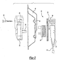
- Figure 3 is a side view of an alternate embodiment for mounting a power drive mechanism within a door panel module.
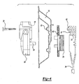
- Figure 4 is a side view of an alternate embodiment for mounting a power drive mechanism within a door panel module.
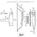
- Figure 5 is a side view of an alternate embodiment for mounting a power drive mechanism within a door panel module.
- Figure 6 is a side view of one embodiment for mounting a manual drive mechanism within a door panel module.
- Figure 7 is a side view of an alternate embodiment for mounting a manual drive mechanism within a door panel module.
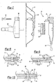
- Figure 8 is a cross-sectional view of an alternate embodiment for mounting a manual or power drive mechanism within a door panel module.
- Figure 9 is a cross-sectional view of an alternate embodiment for mounting a manual or power drive mechanism within a door panel module.
- Figure 10 is a cross-sectional view of an alternate embodiment for mounting a manual or power drive mechanism within a door panel module.
- a vehicle 10 includes a plurality of windows 12 that can be moved between raised and lowered positions.
- Window drive assemblies or window regulators shown generally at 14, are mounted within each door panel module 16 for controlling movement of the windows.
- the drive assemblies 14 can be either manually or electrically driven.
- the mounting apparatus for attaching a drive assembly 14 within the vehicle door module 16 includes a door panel member 18 that is mounted within the door module 16.
- An electric motor drive mechanism 20 is positioned on one side 22 of the panel 18 and a drum assembly 24 is positioned on an opposite side 26 of the panel 18 from the motor 20.
- the drum assembly 24 is positioned on the "wet" side 26 of the door panel 18 and the motor 20 is positioned on the "dry" side 22 of the panel 18, however, the position of the components could also be reversed.
- the drum assembly 24 is comprised of a drum 28 about which a flexible cable member 30 is wound.
- the drum 28 is mounted to a drum-box 32 that is attached to a vehicle door or frame member 34.
- the motor 20 includes a drive shaft 36 that drives the drum 28 to wind or unwind cable 30 from the drum 28 causing the window 12 to be raised or lowered depending on direction of rotation.
- At least one fastener 38 is used to mounting the motor 20 and the drum assembly 24 to the panel 18.
- An adhesive membrane 40 is used to retain the drum assembly 24 to the panel 18.
- the use of the adhesive membrane 40 allows the motor 20 to be selectively detached from the panel 18 by removing the fastener 38 but prevents the drum assembly 24 from detaching from the panel 18.
- the adhesive membrane 40 has adhesive on a first side 42 for adhering to the panel 18 and adhesive on a second side 44 opposite from the first side 42 for adhering to the drum assembly 24. Any type of adhesive known in the art can be used, however, the adhesive should be strong enough to securely hold the drum assembly 24 to the panel 18 without the assistance of the fastener 38.
- the drum assembly 24 includes at least one male member 46 and the motor 20 includes at least one female member 48.
- the male 46 and female 48 members are used to properly locate the motor 20 with respect to the panel 18 and the drum assembly 24.
- the male 46 and female 48 members are mated together during assembly of the motor 20 and drum assembly 24 to the panel 18. It should be understood that position the male 46 and female 48 members could be reversed.
- the male member 46 extends through an opening 50 in the panel 18 when the drum assembly 24 is adhered to the panel 18.
- the female member 48 slides over the male member 46 when the motor 20 is fastened to the panel 18.
- the male member 46 includes a central bore 52 for receiving the fastener 38.
- the fastener is inserted through the motor 20 into the female member 48 and then into the male member 46.
- the male member 46 is cylindrical in shape, as shown in Figure 2.
- the male member is coaxial with the central bore 52 for receiving the fastener 38. It should be understood that the male member 46 could also be located separately from the fastening areas on the drum assembly 24.
- the male member 46 is conical in shape and has a tip 54 that is smaller in diameter than the base 56.
- the adhesive membrane 40 can either be attached first to the panel 18 as indicated at “A” or can be attached first to the drum assembly 24 as indicated at "B".
- the adhesive membrane 30 is adhered to the drum-box 32 such that the drum 38 can engage the motor drive shaft 36 and rotate freely.
- the drum assembly 24 is retained to the panel 18 by a plurality of "sprags" or flexible fingers 58.
- the fingers 58 are spaced about the opening 50 in the panel 18. The fingers grip the male member 46 when the male member is inserted through the opening.
- the male member 46 includes a head portion 60 that is greater in width than a base or neck portion 62. As the male member 46 is inserted through the opening, the fingers 58 flex over the head portion 60 and grip about the neck portion 62.
- the panel 18 can include several openings 50 with fingers 48 and the drum assembly 24 can include several male members 46.
- a handle portion 64 is mounted to the vehicle door panel 18.
- the handle 64 drives the drum assembly 24 to control movement of the window 12.
- a vehicle occupant rotates the handle 64, which moves the window 12 up or down depending on rotational direction.
- the drum assembly includes a male member 66 and the handle 64 includes a female portion 68 that are configured similarly to the power drive interfaces discussed above.
- the male members 66 are cylindrical in shape (Fig. 6) and in an alternate embodiment, the male members 66 are conical in shape (Fig. 7).
- An adhesive membrane 40 (Fig. 6) can be used to retain the drum assembly 24 to the panel 18 or a plurality of flexible fingers 58 (Fig. 7) can be used to retain the drum assembly 24 to the panel 18.
- the adhesive membrane 40 and the flexible fingers 58 operate in a similar manner as discussed above with regard to the power drive mechanism.
- At least one fastener 38 is used to attach the handle 64 to the panel 18 and drum assembly 24. The handle 64 can be removed from the panel 64 selectively and independently from the drum assembly 24 for service operations.
- FIG. 8 An alternate retaining apparatus is shown in Figure 8.
- a stud 70 is threaded along its entire length for insertion into the door panel 18.
- a mid-portion 72 of the stud 70 is threaded into a corresponding threaded hole in the door panel 18.
- Holes 74 and 76 in the drum assembly 24 and drive mechanism 14 respectively pass over the appropriate ends of the stud 70 to ensure that the drum 24 and drive mechanism 14 are aligned properly relative to the panel 18.
- the stud 70 is further utilized to secure the drum 24, panel 18, and drive mechanism 14 since nuts 78, 80 are used to tighten the various components. While preferably the entire length of stud 70 is threaded, it is possible to use a partially threaded or non-threaded stud in order to provide alignment of the various components.
- FIG. 9 An alternate retaining apparatus is shown in Figure 9.
- a first stud 82 is threaded at one end for engagement with the door panel 18 and an opposing second stud 84 is threaded at one end for engagement with the door panel 18.
- the first stud 82 is used to both align and secure the drum assembly 24 relative to the panel 18 and the second stud 84 is used to both align and secure the drive mechanism 14 relative to the door panel 18. While an opposing pair of studs 82, 84 is preferred additional studs could be utilized on both sides to more securely attach the various components.
- FIG. 10 An alternate embodiment is shown in Figure 10.
- a stud 86 is secured to the drum assembly 24 by a swaging technique wherein portions 88 of the stud 86 have been plastically deformed in order that the panel 18 is clamped between these portions 88.
- the subject mounting method and apparatus provides a simple and compact mount for attaching a window drive mechanism within a door module.
- the motor 20 or handle 64 can be removed from the door panel 18 without having to remove the drum assembly 24. This facilitates serviceability of the drive mechanism.
Abstract
Description
- This application relates to a method and apparatus for mounting a window drive mechanism within a vehicle door module.
- Window drive mechanisms are used to move a vehicle door window between raised and lowered positions. The drive mechanisms can be either manually or electrically driven. In a manual drive interface, a handle is mounted to the vehicle door, which is connected to a cable and drum assembly that controls movement of the window. A vehicle occupant rotates the handle, which moves the window up or down depending on rotational direction. In a power drive interface, a motor mounted within the door is used to drive the cable and drum assembly. The vehicle occupant actuates a switch that controls the motor for moving the window up or down.
- There is a limited amount of packaging space available within a door panel module for mounting of the drive mechanism and cable and drum assembly. Thus, the drive mechanism and cable and drum assembly components should be mounted together in a compact manner. Further, if there is a component failure within the window drive mechanism, the drive mechanism should be easily detached from the door panel module so that service operations can be performed.
- Thus, it is desirable to have a mounting method and apparatus that provides a strong structural attachment for the drive mechanism and cable and drum components to the door panel module, and which is compact and easy to assemble and disassemble to perform service operations.
- A mounting apparatus is used to mount a window drive mechanism to a door panel within a vehicle door module. The apparatus includes a manual or electric drive mechanism and a driven mechanism that raises or lowers the window. The drive mechanism is positioned on one side of the panel and the driven mechanism is positioned on an opposite side of the panel from the drive mechanism. A retaining assembly retains the driven and drive mechanisms to the panel such that the drive mechanism can be selectively detached from the panel without detaching the driven mechanism from the panel.
- In one embodiment, the retaining assembly includes an adhesive membrane having adhesive on a first side for adhering to the panel and adhesive on a second side opposite from the first side for adhering to one or the drive or driven mechanisms.
- In an alternate embodiment, the driven mechanism includes at least one male extension member for insertion through an opening in the panel. The drive mechanism includes a female member that receives the male member to properly locate the drive mechanism with respect to the door panel and driven mechanism. The retaining assembly includes a plurality of flexible fingers extending about a perimeter of the opening in the door panel. The flexible fingers grip the extension member when the driven mechanism is mounted to the panel.
- In an alternate embodiment, the retaining assembly includes at least one stud with a threaded portion engaged with the panel and a pair of opposing ends inserted through openings in the drive and driven mechanisms respectively. A first nut retains the stud to the drive mechanism and a second nut retains the stud to the driven mechanism.
- In an alternate embodiment, the retaining assembly includes at least a pair of studs with a first stud having a threaded distal end for engagement with the panel and a first retainer for retaining an opposing end of the first stud to the drive mechanism. A second stud has a threaded distal end for engagement with the panel and a second retainer for retaining an opposing end of the second stud to the driven mechanism.
- In an alternate embodiment, the retaining assembly includes at least one stud extending through openings in the drive and driven mechanism with deformed portions engaging and retaining the stud to the panel between the drive and driven mechanisms.
- The method of assembling a drive mechanism to a door panel includes the following steps. A driven mechanism is retained to one side of the door panel and a drive mechanism is located on an opposite side of the panel with respect to the driven mechanism. The drive mechanism is retained to the panel and driven mechanism such that the drive mechanism is selectively removable from the panel without detaching the driven mechanism from the panel.
- The subject mounting method and apparatus provides a simple and compact mount for attaching a window drive mechanism within a door module. The capability of selectively detaching certain components without having to detach other components facilitates serviceability.
- Figure 1 is schematic view of a vehicle incorporating the subject window drive mechanism mounted within a door panel module.
- Figure 2 is a side view of one embodiment for mounting a power drive mechanism within a door panel module.
- Figure 3 is a side view of an alternate embodiment for mounting a power drive mechanism within a door panel module.
- Figure 4 is a side view of an alternate embodiment for mounting a power drive mechanism within a door panel module.
- Figure 5 is a side view of an alternate embodiment for mounting a power drive mechanism within a door panel module.
- Figure 6 is a side view of one embodiment for mounting a manual drive mechanism within a door panel module.
- Figure 7 is a side view of an alternate embodiment for mounting a manual drive mechanism within a door panel module.
- Figure 8 is a cross-sectional view of an alternate embodiment for mounting a manual or power drive mechanism within a door panel module.
- Figure 9 is a cross-sectional view of an alternate embodiment for mounting a manual or power drive mechanism within a door panel module.
- Figure 10 is a cross-sectional view of an alternate embodiment for mounting a manual or power drive mechanism within a door panel module.
- As shown in Figure 1, a
vehicle 10 includes a plurality ofwindows 12 that can be moved between raised and lowered positions. Window drive assemblies or window regulators, shown generally at 14, are mounted within eachdoor panel module 16 for controlling movement of the windows. Thedrive assemblies 14 can be either manually or electrically driven. - An example of a power drive interfaces is shown in Figure 2. The mounting apparatus for attaching a
drive assembly 14 within thevehicle door module 16 includes adoor panel member 18 that is mounted within thedoor module 16. An electricmotor drive mechanism 20 is positioned on oneside 22 of thepanel 18 and adrum assembly 24 is positioned on anopposite side 26 of thepanel 18 from themotor 20. Preferably, thedrum assembly 24 is positioned on the "wet"side 26 of thedoor panel 18 and themotor 20 is positioned on the "dry"side 22 of thepanel 18, however, the position of the components could also be reversed. - The
drum assembly 24 is comprised of adrum 28 about which aflexible cable member 30 is wound. Thedrum 28 is mounted to a drum-box 32 that is attached to a vehicle door orframe member 34. Themotor 20 includes adrive shaft 36 that drives thedrum 28 to wind or unwindcable 30 from thedrum 28 causing thewindow 12 to be raised or lowered depending on direction of rotation. - At least one
fastener 38 is used to mounting themotor 20 and thedrum assembly 24 to thepanel 18. Preferably at least two (2) or three (3)fasteners 38 are used for attachment purposes, however, only one (1) is shown. - An
adhesive membrane 40 is used to retain thedrum assembly 24 to thepanel 18. The use of theadhesive membrane 40 allows themotor 20 to be selectively detached from thepanel 18 by removing thefastener 38 but prevents thedrum assembly 24 from detaching from thepanel 18. Theadhesive membrane 40 has adhesive on afirst side 42 for adhering to thepanel 18 and adhesive on asecond side 44 opposite from thefirst side 42 for adhering to thedrum assembly 24. Any type of adhesive known in the art can be used, however, the adhesive should be strong enough to securely hold thedrum assembly 24 to thepanel 18 without the assistance of thefastener 38. - The
drum assembly 24 includes at least onemale member 46 and themotor 20 includes at least onefemale member 48. The male 46 and female 48 members are used to properly locate themotor 20 with respect to thepanel 18 and thedrum assembly 24. The male 46 and female 48 members are mated together during assembly of themotor 20 anddrum assembly 24 to thepanel 18. It should be understood that position the male 46 and female 48 members could be reversed. - The
male member 46 extends through an opening 50 in thepanel 18 when thedrum assembly 24 is adhered to thepanel 18. Thefemale member 48 slides over themale member 46 when themotor 20 is fastened to thepanel 18. - In one embodiment, the
male member 46 includes acentral bore 52 for receiving thefastener 38. The fastener is inserted through themotor 20 into thefemale member 48 and then into themale member 46. - Preferably, the
male member 46 is cylindrical in shape, as shown in Figure 2. In this embodiment, the male member is coaxial with thecentral bore 52 for receiving thefastener 38. It should be understood that themale member 46 could also be located separately from the fastening areas on thedrum assembly 24. - In another embodiment shown in Figure 3, the
male member 46 is conical in shape and has atip 54 that is smaller in diameter than thebase 56. - As shown in Figure 4, the
adhesive membrane 40 can either be attached first to thepanel 18 as indicated at "A" or can be attached first to thedrum assembly 24 as indicated at "B". Preferably, theadhesive membrane 30 is adhered to the drum-box 32 such that thedrum 38 can engage themotor drive shaft 36 and rotate freely. - In an alternate embodiment, shown in Figure 5, the
drum assembly 24 is retained to thepanel 18 by a plurality of "sprags" orflexible fingers 58. Thefingers 58 are spaced about theopening 50 in thepanel 18. The fingers grip themale member 46 when the male member is inserted through the opening. In this embodiment, themale member 46 includes ahead portion 60 that is greater in width than a base orneck portion 62. As themale member 46 is inserted through the opening, thefingers 58 flex over thehead portion 60 and grip about theneck portion 62. Although only oneopening 50 is shown, thepanel 18 can includeseveral openings 50 withfingers 48 and thedrum assembly 24 can include severalmale members 46. - In a manual drive interface shown in Figure 6, a
handle portion 64 is mounted to thevehicle door panel 18. Thehandle 64 drives thedrum assembly 24 to control movement of thewindow 12. A vehicle occupant rotates thehandle 64, which moves thewindow 12 up or down depending on rotational direction. - The drum assembly includes a
male member 66 and thehandle 64 includes afemale portion 68 that are configured similarly to the power drive interfaces discussed above. In one embodiment, themale members 66 are cylindrical in shape (Fig. 6) and in an alternate embodiment, themale members 66 are conical in shape (Fig. 7). - An adhesive membrane 40 (Fig. 6) can be used to retain the
drum assembly 24 to thepanel 18 or a plurality of flexible fingers 58 (Fig. 7) can be used to retain thedrum assembly 24 to thepanel 18. Theadhesive membrane 40 and theflexible fingers 58 operate in a similar manner as discussed above with regard to the power drive mechanism. At least onefastener 38 is used to attach thehandle 64 to thepanel 18 anddrum assembly 24. Thehandle 64 can be removed from thepanel 64 selectively and independently from thedrum assembly 24 for service operations. - An alternate retaining apparatus is shown in Figure 8. A
stud 70 is threaded along its entire length for insertion into thedoor panel 18. A mid-portion 72 of thestud 70 is threaded into a corresponding threaded hole in thedoor panel 18.Holes drum assembly 24 anddrive mechanism 14 respectively pass over the appropriate ends of thestud 70 to ensure that thedrum 24 anddrive mechanism 14 are aligned properly relative to thepanel 18. Thestud 70 is further utilized to secure thedrum 24,panel 18, and drivemechanism 14 sincenuts stud 70 is threaded, it is possible to use a partially threaded or non-threaded stud in order to provide alignment of the various components. - An alternate retaining apparatus is shown in Figure 9. Minimally, a
first stud 82 is threaded at one end for engagement with thedoor panel 18 and an opposingsecond stud 84 is threaded at one end for engagement with thedoor panel 18. Thefirst stud 82 is used to both align and secure thedrum assembly 24 relative to thepanel 18 and thesecond stud 84 is used to both align and secure thedrive mechanism 14 relative to thedoor panel 18. While an opposing pair ofstuds - An alternate embodiment is shown in Figure 10. A
stud 86 is secured to thedrum assembly 24 by a swaging technique whereinportions 88 of thestud 86 have been plastically deformed in order that thepanel 18 is clamped between theseportions 88. - The subject mounting method and apparatus provides a simple and compact mount for attaching a window drive mechanism within a door module. The
motor 20 or handle 64 can be removed from thedoor panel 18 without having to remove thedrum assembly 24. This facilitates serviceability of the drive mechanism. - Preferred embodiments of this invention have been disclosed, however, a worker of ordinary skill in the art would recognize that certain modifications would come within the scope of this invention. For that reason the following claims should be studied to determine the true scope and content of this invention.
Claims (20)
- An apparatus for mounting a drive mechanism within a vehicle door to move a window comprising:a door panel;a drive mechanism positioned on one side of said panel;a drum assembly positioned on an opposite side of said panel from said drive mechanism;at least one fastener for mounting said drive mechanism and said drum assembly to said panel; anda retaining member for retaining said drum assembly to said panel wherein said drive mechanism can be selectively detached from said panel by removing said fastener without detaching drum assembly from said panel.
- An apparatus according to claim 1 wherein said drum assembly includes at least one first locating portion and said drive mechanism includes at least one second locating portion, said first and second locating portions being mated together during assembly of said drive mechanism and drum assembly to said panel.
- An apparatus according to claim 2 wherein said first locating member is a male member extending through said panel when said drum assembly is adhered to said panel and said second locating member is a female member that receives said male member when said drive mechanism is fastened to said panel.
- An apparatus according to claim 3 wherein said male member includes a central bore for receiving said fastener.
- An apparatus according to claim 3 wherein said male member has a cylindrical shape.
- An apparatus according to claim 5 wherein said cylindrical male member is coaxial with said central bore
- An apparatus according to claim 3 wherein said male member has a conical shape.
- An apparatus according to claim 1 wherein said retaining member is an adhesive membrane having adhesive on a first side for adhering to said panel and adhesive on a second side opposite from said first side for adhering to said drum assembly.
- An apparatus according to claim 8 wherein said drum assembly includes at least one male locating member and said drive mechanism includes at least one female locating member for receiving said male locating member when said drive mechanism and said drum assembly are assembled to said panel, said membrane including at least one opening such that said male locating member extends through said membrane to engage said female locating member.
- An apparatus according to claim 1 wherein said drum assembly includes at least one male extension member for insertion through an opening in said panel and wherein said retaining member is comprised of a plurality of flexible fingers extending about a perimeter of said opening, said flexible fingers for gripping said extension member when said drum assembly is mounted to said panel.
- An apparatus according to claim 10 wherein said male extension member includes a head portion having a first width and a neck portion having a second width less than said first width, said flexible fingers flexing over said head portion to grip said neck portion when said drum assembly is mounted to said panel.
- A method of assembling a drive mechanism to a door panel comprising the steps of:(a) retaining a driven mechanism for raising or lowering a window to one side of the door panel;(b) locating a drive mechanism on an opposite side of the panel with respect to the driven mechanism;(c) retaining the drive mechanism to the panel and driven mechanism with a retaining assembly such that the drive mechanism is selectively removable from the panel without detaching the driven mechanism from the panel.
- The method according to claim 12 wherein step (c) includes mounting an adhesive member between the panel and driven mechanism to retain the driven mechanism to the panel and fastening the drive mechanism to the panel independently from the adhesive.
- The method according to claim 12 wherein step (c) includes inserting at least one stud through the drive mechanism, panel, and driven mechanism to selectively retain the driven mechanism to the panel without retaining the driven mechanism to the panel.
- The method according to claim 12 including the step of unfastening and detaching the drive mechanism from the panel while leaving the driven mechanism attached to the panel.
- An apparatus for mounting a drive mechanism within a vehicle door to move a window comprising:a door panel;a drive mechanism positioned on one side of said panel;a driven mechanism positioned on an opposite side of said panel from said drive mechanism; anda retaining assembly for retaining said driven and drive mechanisms to said panel wherein said drive mechanism can be selectively detached from said panel without detaching said driven mechanism from said panel.
- An apparatus according to claim 16 wherein said retaining assembly includes at least one stud having a threaded portion engaged with said panel and a pair of opposing ends inserted through openings in said drive and driven mechanisms respectively with a first nut retaining said stud to said drive mechanism and a second nut retaining said stud to said driven mechanism.
- An apparatus according to claim 16 wherein said retaining assembly includes at least a pair of studs with a first stud having a threaded distal end for engagement with said panel and a first retainer for retaining an opposing end of said first stud to said drive mechanism and a second stud having a threaded distal end for engagement with said panel and a second retainer for retaining an opposing end of said second stud to said driven mechanism.
- An apparatus according to claim 16 wherein said retaining assembly includes at least one stud extending through openings in said drive and driven mechanism with deformed portions engaging and retaining said stud to said panel between said drive and driven mechanisms.
- An apparatus according to claim 16 wherein said retaining assembly includes at least one fastener for mounting said drive mechanism and said driven mechanism to said panel and an adhesive membrane having adhesive on a first side for adhering to said panel and adhesive on a second side opposite from said first side for adhering to said drum assembly.
Applications Claiming Priority (4)
| Application Number | Priority Date | Filing Date | Title |
|---|---|---|---|
| US18897300P | 2000-03-10 | 2000-03-10 | |
| US188973P | 2000-03-10 | ||
| GB0024104A GB0024104D0 (en) | 2000-10-03 | 2000-10-03 | Door pannel assembly |
| GB0024104 | 2000-10-03 |
Publications (3)
| Publication Number | Publication Date |
|---|---|
| EP1132236A2 true EP1132236A2 (en) | 2001-09-12 |
| EP1132236A3 EP1132236A3 (en) | 2003-04-16 |
| EP1132236B1 EP1132236B1 (en) | 2005-05-11 |
Family
ID=26245088
Family Applications (2)
| Application Number | Title | Priority Date | Filing Date |
|---|---|---|---|
| EP01302092A Expired - Lifetime EP1132235B1 (en) | 2000-03-10 | 2001-03-07 | Door panel assembly |
| EP01302093A Expired - Lifetime EP1132236B1 (en) | 2000-03-10 | 2001-03-07 | Method and apparatus for mounting a drive mechanism within a door module |
Family Applications Before (1)
| Application Number | Title | Priority Date | Filing Date |
|---|---|---|---|
| EP01302092A Expired - Lifetime EP1132235B1 (en) | 2000-03-10 | 2001-03-07 | Door panel assembly |
Country Status (4)
| Country | Link |
|---|---|
| US (3) | US6684568B2 (en) |
| EP (2) | EP1132235B1 (en) |
| DE (2) | DE60110663T2 (en) |
| ES (1) | ES2242709T3 (en) |
Cited By (1)
| Publication number | Priority date | Publication date | Assignee | Title |
|---|---|---|---|---|
| WO2018046506A1 (en) * | 2016-09-06 | 2018-03-15 | Brose Fahrzeugteile Gmbh & Co. Kommanditgesellschaft, Bamberg | Drive device for a window opener, with a bearing structure on a carrier element |
Families Citing this family (29)
| Publication number | Priority date | Publication date | Assignee | Title |
|---|---|---|---|---|
| GB0026148D0 (en) * | 2000-10-26 | 2000-12-13 | Meritor Light Vehicle Sys Ltd | Assembly |
| GB0030097D0 (en) * | 2000-12-09 | 2001-01-24 | Meritor Light Vehicle Sys Ltd | Assembly |
| GB0030532D0 (en) * | 2000-12-14 | 2001-01-31 | Meritor Automotive Gmbh | Window regulator assembly |
| GB0102987D0 (en) * | 2001-02-07 | 2001-03-21 | Meritor Light Vehicle Sys Ltd | An assembly |
| GB0107066D0 (en) * | 2001-03-21 | 2001-05-09 | Meritor Light Vehicle Sys Ltd | Door panel assembly |
| FR2836507A1 (en) * | 2002-02-22 | 2003-08-29 | Arvinmeritor Light Vehicle Sys | Window lifter device of vehicle door comprises cable-winding drum that turns inside a housing about rotational axis |
| ES2241386B1 (en) * | 2002-07-22 | 2007-02-16 | Grupo Antolin-Ingenieria , S.A | ASSEMBLY DEVICE OF AN ELEVALUNAS ENGINE AND ASSOCIATED KINEMATICS. |
| ES2241387B1 (en) * | 2002-07-22 | 2007-02-16 | Grupo Antolin - Ingenieria, S.A | ASSEMBLY DEVICE OF AN ELEVALUNAS ENGINE AND ASSOCIATED KINEMATICS. |
| US7591104B2 (en) * | 2003-07-23 | 2009-09-22 | Ohi Seisakusho Co., Ltd. | Mounting structure of a power window apparatus |
| FR2857908B1 (en) * | 2003-07-25 | 2005-09-09 | Arvinmeritor Light Vehicle Sys | WINDOW ACTUATOR DEVICE HOUSING |
| ES1056348Y (en) * | 2003-12-12 | 2004-07-01 | Castellon Melchor Daumal | SUPPORT FOR ELEVALUNAS ELECTRIC MOTORS FOR THE CAR. |
| FR2877864B1 (en) * | 2004-11-16 | 2008-02-01 | Renault Sas | FIXING OF SHEET BY TAPERED FLUO TAPERED |
| DE102004061254A1 (en) * | 2004-12-20 | 2006-06-29 | Arvinmeritor Light Vehicle Systems-France | Assembly with a window lift drive and an associated motor / gear unit |
| ATE392329T1 (en) * | 2005-06-16 | 2008-05-15 | Antolin Grupo Ing Sa | MODULE SUPPORT FOR VEHICLE DOORS, DOOR ARRANGEMENT FOR MOTOR VEHICLES AND METHOD FOR MOUNTING THE MODULE SUPPORT ON A DOOR FRAME |
| JP2007056501A (en) * | 2005-08-23 | 2007-03-08 | Johnan Seisakusho Co Ltd | Wire drum type window regulator |
| DE202005018470U1 (en) * | 2005-11-25 | 2006-02-16 | Arvinmeritor Light Vehicle Systems-France | Assembly consisting of a support part and a door inner part |
| US20080098655A1 (en) * | 2006-10-31 | 2008-05-01 | Jeffrey Valentage | Integrated bracket for mounting pulley |
| FR2917141A3 (en) * | 2007-06-05 | 2008-12-12 | Renault Sas | Component i.e. inner opening control box, fixing arrangement for door of motor vehicle, has elastic deformable plate including orifice for passing one fixation element i.e. screw, and adhesive surface that is stuck against wall |
| EP2246210B1 (en) * | 2008-02-28 | 2017-07-05 | Aisin Seiki Kabushiki Kaisha | Vehicle door opening/closing device |
| US8641128B2 (en) * | 2009-08-07 | 2014-02-04 | Honda Motor Co., Ltd. | Vehicle floor assembly with insert |
| JP5937295B2 (en) * | 2010-04-12 | 2016-06-22 | シロキ工業株式会社 | Coupling structure and window regulator |
| US8544236B2 (en) * | 2011-08-10 | 2013-10-01 | Newfrey Llc | Fascia bracket with quarter turn locking nut |
| JP5981132B2 (en) * | 2011-12-15 | 2016-08-31 | 株式会社ハイレックスコーポレーション | Seal structure |
| JP5826736B2 (en) * | 2012-11-21 | 2015-12-02 | 株式会社豊田自動織機 | Vehicle door reinforcement structure |
| EP3251125B1 (en) * | 2015-01-29 | 2018-12-26 | Framatome GmbH | Method of preparing irradiation targets for radioisotope production and irradiation target |
| JP2017203291A (en) * | 2016-05-11 | 2017-11-16 | シロキ工業株式会社 | Drive unit of opening/closing body for vehicle |
| DE102016216876A1 (en) * | 2016-09-06 | 2018-03-08 | Brose Fahrzeugteile Gmbh & Co. Kommanditgesellschaft, Bamberg | Drive device for a window regulator |
| DE102016216877A1 (en) * | 2016-09-06 | 2018-03-08 | Brose Fahrzeugteile Gmbh & Co. Kommanditgesellschaft, Bamberg | Drive device for a window lift, with a stop ring for a cable drum |
| US11208838B2 (en) * | 2019-05-22 | 2021-12-28 | Toyota Motor Engineering & Manufacturing North America, Inc. | Window clip release system |
Family Cites Families (54)
| Publication number | Priority date | Publication date | Assignee | Title |
|---|---|---|---|---|
| US1858070A (en) * | 1930-05-17 | 1932-05-10 | Ackerman Blaesserfezzy Inc | Center lift window regulator |
| US1986981A (en) * | 1933-06-12 | 1935-01-08 | Rostone Inc | Means for fastening metal shapes |
| US2381365A (en) * | 1943-01-30 | 1945-08-07 | Malcolm W Fraser | Window regulator mechanism |
| US2438185A (en) | 1944-08-30 | 1948-03-23 | Briggs Mfg Co | Door structure for motor vehicles |
| US2905003A (en) * | 1956-06-11 | 1959-09-22 | Gen Motors Corp | Window regulator drive mechanism |
| DE1285357B (en) * | 1963-11-27 | 1968-12-12 | Porsche Kg | Adjusting device for vertically sliding windows |
| DE2132067A1 (en) * | 1971-06-28 | 1973-01-11 | Brose & Co Metallwerk Max | ELECTRICALLY DRIVEN WINDOW REGULATORS |
| US3771410A (en) * | 1972-05-01 | 1973-11-13 | Vsi Corp | Fastener |
| IT1076421B (en) * | 1977-03-31 | 1985-04-27 | Sessa T | IMPROVEMENTS RELATED TO WIRE WINDOWS, IN PARTICULAR FOR VEHICLES |
| US4229906A (en) * | 1978-08-02 | 1980-10-28 | Ferro Manufacturing Corporation | Window regulator |
| US4310273A (en) * | 1979-04-30 | 1982-01-12 | Textron Inc. | Fastener assembly |
| DE3148523C2 (en) * | 1981-12-08 | 1985-10-03 | Brose Fahrzeugteile GmbH & Co KG, 8630 Coburg | Window lifter drives, in particular for motor vehicles |
| JPS615186A (en) * | 1984-06-18 | 1986-01-10 | 株式会社大井製作所 | Window regulator for car |
| DE3519056A1 (en) * | 1985-05-28 | 1986-12-04 | Brose Fahrzeugteile GmbH & Co KG, 8630 Coburg | WINDOW REGULATOR DRIVE UNIT, IN PARTICULAR FOR A ROPE WINDOW REGULATOR |
| JPH0316862Y2 (en) * | 1987-01-16 | 1991-04-10 | ||
| JPS63177583U (en) * | 1987-05-01 | 1988-11-17 | ||
| US4943109A (en) * | 1988-08-09 | 1990-07-24 | Ford Motor Company | Automotive door assembly having a plug-in electrified interior panel |
| JPH0260824A (en) | 1988-08-25 | 1990-03-01 | Honda Motor Co Ltd | On-vehicle door structure |
| US4848032A (en) * | 1988-12-27 | 1989-07-18 | Chrysler Motors Corporation | Arrangement for mounting automotive glass to liftplate |
| US4998332A (en) * | 1989-02-06 | 1991-03-12 | Utica Enterprises, Inc. | Method for body panel attachment |
| DE3930106C2 (en) * | 1989-09-09 | 1997-09-04 | Brose Fahrzeugteile | Rope window regulator for motor vehicles |
| US5011356A (en) * | 1990-01-25 | 1991-04-30 | Itw-Mapri Industria E Comercio Ltda | Panel fastener |
| FR2660255B1 (en) | 1990-04-02 | 1992-07-24 | Rockwell Cim | CONNECTION DEVICE BETWEEN A VEHICLE DOOR WINDOW PROFILE AND A WINDOW SLIDING PROFILE, AND VEHICLE DOOR EQUIPPED WITH THIS DEVICE. |
| US5199310A (en) * | 1990-06-26 | 1993-04-06 | Nippon Cable System Inc. | Driving device for cable type window regulator |
| US5102090A (en) * | 1991-05-02 | 1992-04-07 | General Motors Corporation | Power window motor mounting bracket |
| US5251370A (en) * | 1991-10-31 | 1993-10-12 | Profil Verbindungstechnik Gmbh & Co. | Method of attaching a fastening element to a panel |
| US5230137A (en) * | 1991-11-08 | 1993-07-27 | Sanyo Machine America Corporation | Method for fastening together two or more non-aligned parts |
| US5251403A (en) * | 1992-03-16 | 1993-10-12 | General Motors Corporation | Tubular plastic mounting panel for door hardware |
| EP0663535A1 (en) * | 1992-07-03 | 1995-07-19 | Emhart Inc. | Component mounting assembly and method |
| US5325631A (en) * | 1993-03-25 | 1994-07-05 | A.L. Hansen Mfg. Co. | Window regulator |
| US5581952A (en) * | 1994-03-04 | 1996-12-10 | Chrysler Corporation | Vehicle window actuator mounting arrangement |
| JP3409926B2 (en) * | 1994-03-15 | 2003-05-26 | アスモ株式会社 | Window regulator |
| DE4437532C2 (en) * | 1994-10-20 | 1996-12-12 | Brose Fahrzeugteile | Device for connecting a window lifter to the sliding window pane of a motor vehicle |
| DE19504692A1 (en) * | 1995-02-13 | 1996-08-14 | United Carr Gmbh Trw | Connection between a support and a plate element |
| DE19509282A1 (en) * | 1995-03-15 | 1996-11-14 | Brose Fahrzeugteile | Vehicle door |
| US5802770A (en) * | 1996-09-25 | 1998-09-08 | Atoma International Inc. | Door cartridge having a door latch mounting assembly |
| JPH09119260A (en) * | 1995-10-24 | 1997-05-06 | Aisin Seiki Co Ltd | Window opening-closing device for car |
| US5694719A (en) * | 1995-11-03 | 1997-12-09 | Ford Motor Company | Snap-in slip joint adjusting attachment |
| US5749174A (en) * | 1996-03-11 | 1998-05-12 | Excel Industries, Inc. | Window regulator with spring retainer |
| DE19619087C2 (en) * | 1996-04-30 | 2002-05-16 | Brose Fahrzeugteile | fastening device |
| DE19654956B4 (en) | 1996-06-04 | 2005-06-23 | Brose Fahrzeugteile Gmbh & Co. Kommanditgesellschaft, Coburg | Motor vehicle door |
| US5890321A (en) * | 1996-08-05 | 1999-04-06 | General Motors Corporation | Window regulator mounting panel |
| US5832667A (en) * | 1996-11-13 | 1998-11-10 | Excel Industries, Inc. | Self aligning window regulator |
| DE19707850C1 (en) * | 1997-02-27 | 1998-03-12 | Brose Fahrzeugteile | Motor-drive unit e.g. for adjustment device mounted in motor vehicle door panel |
| DE19755899C2 (en) * | 1997-12-08 | 2003-01-16 | Brose Fahrzeugteile | Drive unit for adjustment devices |
| DE19914598B4 (en) * | 1998-04-02 | 2008-07-03 | Asmo Co., Ltd., Kosai | Mounting arrangement and actuator for a window with power window |
| DE29810437U1 (en) * | 1998-06-10 | 1998-10-01 | Trw Automotive Electron & Comp | Connecting element between a carrier, in particular a body part of a motor vehicle and a plate element |
| US6164684A (en) * | 1998-08-31 | 2000-12-26 | Trw Vehicle Safety Systems Inc. | Fastening structure for interconnecting parts of a vehicle occupant protection apparatus |
| US6183038B1 (en) * | 1999-03-11 | 2001-02-06 | Delphi Technologies, Inc. | Door trim assembly and method of making same |
| US6397524B1 (en) * | 1999-06-16 | 2002-06-04 | Mitsubishi Jidosha Kogyo Kabushiki Kaisha | Door glass raising and falling apparatus |
| JP3474496B2 (en) * | 1999-09-21 | 2003-12-08 | アスモ株式会社 | Reciprocating drive |
| FR2799493B1 (en) * | 1999-10-07 | 2001-11-23 | Sai Automotive Sal Gmbh | ASSEMBLY COMPRISING AN INTERIOR VEHICLE DOOR LINING AND A WINDOW MECHANISM ATTACHED TO THIS LINING |
| JP2001119236A (en) | 1999-10-14 | 2001-04-27 | Tokai Rubber Ind Ltd | Electromagnetic wave shield film |
| JP2001199236A (en) * | 2000-01-20 | 2001-07-24 | Yazaki Corp | Auxiliary machine assembling structure for automobile door and auxiliary machine assembling method |
-
2001
- 2001-03-07 DE DE60110663T patent/DE60110663T2/en not_active Expired - Fee Related
- 2001-03-07 ES ES01302093T patent/ES2242709T3/en not_active Expired - Lifetime
- 2001-03-07 EP EP01302092A patent/EP1132235B1/en not_active Expired - Lifetime
- 2001-03-07 DE DE60123691T patent/DE60123691T2/en not_active Expired - Fee Related
- 2001-03-07 EP EP01302093A patent/EP1132236B1/en not_active Expired - Lifetime
- 2001-03-08 US US09/802,106 patent/US6684568B2/en not_active Expired - Fee Related
- 2001-03-08 US US09/802,130 patent/US6634142B2/en not_active Expired - Fee Related
-
2003
- 2003-08-06 US US10/635,130 patent/US20040025441A1/en not_active Abandoned
Non-Patent Citations (1)
| Title |
|---|
| None |
Cited By (5)
| Publication number | Priority date | Publication date | Assignee | Title |
|---|---|---|---|---|
| WO2018046506A1 (en) * | 2016-09-06 | 2018-03-15 | Brose Fahrzeugteile Gmbh & Co. Kommanditgesellschaft, Bamberg | Drive device for a window opener, with a bearing structure on a carrier element |
| KR20190039800A (en) * | 2016-09-06 | 2019-04-15 | 브로제 파초이크타일레 게엠베하 운트 코. 콤만디트게젤샤프트, 밤베르크 | Driving device for a window opening machine having a bearing structure on a carrier element |
| CN109661499A (en) * | 2016-09-06 | 2019-04-19 | 布罗泽汽车部件制造班贝克有限公司 | For the driving equipment of window lifter, there is the structure that reclines on load-carrying unit |
| CN109661499B (en) * | 2016-09-06 | 2020-12-18 | 布罗泽汽车部件制造班贝克有限公司 | Drive device for a window lifter, comprising an abutment on a carrier element |
| US11187024B2 (en) | 2016-09-06 | 2021-11-30 | Brose Fahrzeugteile Gmbh & Co. Kommanditgesellschaft, Bamberg | Drive device for a window opener, with a bearing structure on a carrier element |
Also Published As
| Publication number | Publication date |
|---|---|
| EP1132236A3 (en) | 2003-04-16 |
| DE60123691D1 (en) | 2006-11-23 |
| DE60110663T2 (en) | 2006-02-02 |
| US20040025441A1 (en) | 2004-02-12 |
| DE60123691T2 (en) | 2007-08-23 |
| US20010034975A1 (en) | 2001-11-01 |
| DE60110663D1 (en) | 2005-06-16 |
| US6634142B2 (en) | 2003-10-21 |
| EP1132235B1 (en) | 2006-10-11 |
| ES2242709T3 (en) | 2005-11-16 |
| US20020040554A1 (en) | 2002-04-11 |
| EP1132235A3 (en) | 2003-05-28 |
| EP1132236B1 (en) | 2005-05-11 |
| EP1132235A2 (en) | 2001-09-12 |
| US6684568B2 (en) | 2004-02-03 |
Similar Documents
| Publication | Publication Date | Title |
|---|---|---|
| EP1132236B1 (en) | Method and apparatus for mounting a drive mechanism within a door module | |
| US6715812B2 (en) | Method of mounting assist grip and mounting structure thereof | |
| CA2101981C (en) | Method and hinge structure for temporarily installing a door with a vehicle for subsequent removal from the vehicle or the temporary connection of a body half of a hinge with a door half of a hinge and for subsequent separation of the halves | |
| US6895635B2 (en) | Accessory mounting mechanism | |
| MX2015000240A (en) | Photovoltaic frame fastener. | |
| US8061437B2 (en) | Nail gun with rapidly attachable and detachable magazine assembly | |
| US6460296B1 (en) | Motor vehicle door window lifter device | |
| CN110191771B (en) | Fastening tool | |
| JP2001513858A (en) | Cable window lifter | |
| US11185913B2 (en) | Fastening tool | |
| EP1570147B1 (en) | An adjustable hinge assembly | |
| US6848215B2 (en) | Assembly for attaching a window regulator motor to a window regulator mechanism through a door panel | |
| CN114654406B (en) | A installation frock assembly for installing dropper on contact line | |
| US20100326855A1 (en) | Fastener, fastener assembly and a method for feeding said fasteners to a fastener driving tool | |
| CN219042701U (en) | Mounting part, endoscope handle and endoscope | |
| KR200187181Y1 (en) | A regulator of windows for vehicle | |
| JP3041564U (en) | Door lock handle device | |
| JP2768636B2 (en) | Reaction force receiving structure of screw tightening machine | |
| JPH0640864Y2 (en) | Automatic door drive mounting device | |
| JP3835069B2 (en) | Fastener magazine spring spring mounting device | |
| KR200160399Y1 (en) | A binding structure of wiper blade for windshield wiper | |
| US20030019092A1 (en) | Wiping system for wiping a window, particularly for motor vehicle window pane and method of assembling same | |
| JP2002279940A (en) | Base removing device | |
| KR0139811Y1 (en) | Power window motor | |
| KR20040044818A (en) | Door regulator handle setting device |
Legal Events
| Date | Code | Title | Description |
|---|---|---|---|
| PUAI | Public reference made under article 153(3) epc to a published international application that has entered the european phase |
Free format text: ORIGINAL CODE: 0009012 |
|
| AK | Designated contracting states |
Kind code of ref document: A2 Designated state(s): AT BE CH CY DE DK ES FI FR GB GR IE IT LI LU MC NL PT SE TR |
|
| AX | Request for extension of the european patent |
Free format text: AL;LT;LV;MK;RO;SI |
|
| RIN1 | Information on inventor provided before grant (corrected) |
Inventor name: HERWIG, ARND Inventor name: DOBSON, SIMON |
|
| PUAL | Search report despatched |
Free format text: ORIGINAL CODE: 0009013 |
|
| AK | Designated contracting states |
Designated state(s): AT BE CH CY DE DK ES FI FR GB GR IE IT LI LU MC NL PT SE TR |
|
| AX | Request for extension of the european patent |
Extension state: AL LT LV MK RO SI |
|
| RIC1 | Information provided on ipc code assigned before grant |
Ipc: 7E 05F 15/16 B Ipc: 7B 60J 1/17 B Ipc: 7B 60J 5/04 A |
|
| 17P | Request for examination filed |
Effective date: 20030627 |
|
| 17Q | First examination report despatched |
Effective date: 20030812 |
|
| RAP1 | Party data changed (applicant data changed or rights of an application transferred) |
Owner name: ARVINMERITOR LIGHT VEHICLE SYSTEMS-FRANCE |
|
| AKX | Designation fees paid |
Designated state(s): DE ES FR GB IT |
|
| GRAP | Despatch of communication of intention to grant a patent |
Free format text: ORIGINAL CODE: EPIDOSNIGR1 |
|
| GRAS | Grant fee paid |
Free format text: ORIGINAL CODE: EPIDOSNIGR3 |
|
| GRAA | (expected) grant |
Free format text: ORIGINAL CODE: 0009210 |
|
| AK | Designated contracting states |
Kind code of ref document: B1 Designated state(s): DE ES FR GB IT |
|
| REG | Reference to a national code |
Ref country code: GB Ref legal event code: FG4D |
|
| REG | Reference to a national code |
Ref country code: IE Ref legal event code: FG4D |
|
| REF | Corresponds to: |
Ref document number: 60110663 Country of ref document: DE Date of ref document: 20050616 Kind code of ref document: P |
|
| REG | Reference to a national code |
Ref country code: ES Ref legal event code: FG2A Ref document number: 2242709 Country of ref document: ES Kind code of ref document: T3 |
|
| PG25 | Lapsed in a contracting state [announced via postgrant information from national office to epo] |
Ref country code: GB Free format text: LAPSE BECAUSE OF NON-PAYMENT OF DUE FEES Effective date: 20060307 |
|
| PGFP | Annual fee paid to national office [announced via postgrant information from national office to epo] |
Ref country code: FR Payment date: 20060317 Year of fee payment: 6 |
|
| PLBE | No opposition filed within time limit |
Free format text: ORIGINAL CODE: 0009261 |
|
| STAA | Information on the status of an ep patent application or granted ep patent |
Free format text: STATUS: NO OPPOSITION FILED WITHIN TIME LIMIT |
|
| ET | Fr: translation filed | ||
| PGFP | Annual fee paid to national office [announced via postgrant information from national office to epo] |
Ref country code: ES Payment date: 20060327 Year of fee payment: 6 |
|
| PGFP | Annual fee paid to national office [announced via postgrant information from national office to epo] |
Ref country code: IT Payment date: 20060331 Year of fee payment: 6 |
|
| PGFP | Annual fee paid to national office [announced via postgrant information from national office to epo] |
Ref country code: DE Payment date: 20060502 Year of fee payment: 6 |
|
| 26N | No opposition filed |
Effective date: 20060214 |
|
| GBPC | Gb: european patent ceased through non-payment of renewal fee |
Effective date: 20060307 |
|
| REG | Reference to a national code |
Ref country code: FR Ref legal event code: ST Effective date: 20071130 |
|
| PG25 | Lapsed in a contracting state [announced via postgrant information from national office to epo] |
Ref country code: DE Free format text: LAPSE BECAUSE OF NON-PAYMENT OF DUE FEES Effective date: 20071002 |
|
| REG | Reference to a national code |
Ref country code: ES Ref legal event code: FD2A Effective date: 20070308 |
|
| PG25 | Lapsed in a contracting state [announced via postgrant information from national office to epo] |
Ref country code: FR Free format text: LAPSE BECAUSE OF NON-PAYMENT OF DUE FEES Effective date: 20070402 Ref country code: ES Free format text: LAPSE BECAUSE OF NON-PAYMENT OF DUE FEES Effective date: 20070308 |
|
| PG25 | Lapsed in a contracting state [announced via postgrant information from national office to epo] |
Ref country code: IT Free format text: LAPSE BECAUSE OF NON-PAYMENT OF DUE FEES Effective date: 20070307 |