EP1132191B1 - Planetary gear extruder - Google Patents
Planetary gear extruder Download PDFInfo
- Publication number
- EP1132191B1 EP1132191B1 EP01104349A EP01104349A EP1132191B1 EP 1132191 B1 EP1132191 B1 EP 1132191B1 EP 01104349 A EP01104349 A EP 01104349A EP 01104349 A EP01104349 A EP 01104349A EP 1132191 B1 EP1132191 B1 EP 1132191B1
- Authority
- EP
- European Patent Office
- Prior art keywords
- planetary gear
- spindles
- planetary
- recesses
- spindle
- Prior art date
- Legal status (The legal status is an assumption and is not a legal conclusion. Google has not performed a legal analysis and makes no representation as to the accuracy of the status listed.)
- Expired - Lifetime
Links
Images

Classifications
-
- B—PERFORMING OPERATIONS; TRANSPORTING
- B29—WORKING OF PLASTICS; WORKING OF SUBSTANCES IN A PLASTIC STATE IN GENERAL
- B29C—SHAPING OR JOINING OF PLASTICS; SHAPING OF MATERIAL IN A PLASTIC STATE, NOT OTHERWISE PROVIDED FOR; AFTER-TREATMENT OF THE SHAPED PRODUCTS, e.g. REPAIRING
- B29C48/00—Extrusion moulding, i.e. expressing the moulding material through a die or nozzle which imparts the desired form; Apparatus therefor
- B29C48/25—Component parts, details or accessories; Auxiliary operations
- B29C48/36—Means for plasticising or homogenising the moulding material or forcing it through the nozzle or die
- B29C48/395—Means for plasticising or homogenising the moulding material or forcing it through the nozzle or die using screws surrounded by a cooperating barrel, e.g. single screw extruders
- B29C48/40—Means for plasticising or homogenising the moulding material or forcing it through the nozzle or die using screws surrounded by a cooperating barrel, e.g. single screw extruders using two or more parallel screws or at least two parallel non-intermeshing screws, e.g. twin screw extruders
- B29C48/435—Sub-screws
- B29C48/44—Planetary screws
-
- B—PERFORMING OPERATIONS; TRANSPORTING
- B29—WORKING OF PLASTICS; WORKING OF SUBSTANCES IN A PLASTIC STATE IN GENERAL
- B29C—SHAPING OR JOINING OF PLASTICS; SHAPING OF MATERIAL IN A PLASTIC STATE, NOT OTHERWISE PROVIDED FOR; AFTER-TREATMENT OF THE SHAPED PRODUCTS, e.g. REPAIRING
- B29C48/00—Extrusion moulding, i.e. expressing the moulding material through a die or nozzle which imparts the desired form; Apparatus therefor
- B29C48/03—Extrusion moulding, i.e. expressing the moulding material through a die or nozzle which imparts the desired form; Apparatus therefor characterised by the shape of the extruded material at extrusion
Definitions
- Planetary roller extruders are used to produce plastic melt, preferably for the preparation of sensitive molding compounds.
- Several planetary spindles are arranged between a roll cylinder and a main spindle.
- the teeth integrated in the roll cylinders, planetary spindles and main spindle roll on each other, so that the plastic material to be plasticized is subjected to an intensive kneading action.
- the plastic melt produced in this way has a high quality.
- the plasticizing process in a planetary roller extruder takes place in the roller part.
- the material to be processed is converted into a plastic state, thereby forming a kneading.
- the invention is therefore the object of developing a planetary roller extruder so that an unnecessarily long machine design is unnecessary and thus the increased energy loss, in particular by cooling, is avoided, at the same time good plasticization and dispersion of the plastic material.
- the solution of the problem is characterized in that the axial distance between at least two adjacent planetary spindles is smaller than the tip diameter of the teeth of the planetary spindles, wherein the planetary spindles provided at least with a recess or a recess, or over a defined length of the planetary spindle extends.
- gaps remain between two adjacent planetary spindles which are between 0.2 and 5 mm, preferably 1 mm.
- This segmental recess of the planetary spindles allows the planetary spindles to run into each other without them touching each other.
- the advantage of this embodiment is that all surfaces comb each other. Neighboring planetary spindles mesh with the groove, the toothing of the planetary spindle with the main spindle and the roll cylinder.
- the recesses or grooves of the planetary spindles have straight side edges. According to an advantageous development, the side edges form with the longitudinal axis of the planetary spindle an angle which is between 70 ° and 150 °, preferably 90 °.
- the loose spindles run against a stop, the so-called stop ring. In this situation, it must be ensured that adjacent planetary spindles do not touch and are therefore not damaged. To prevent such damage to the planetary spindles, it is provided to place the recesses or recesses so that there is always a certain amount of play between the projection of two spindles.
- the planetary spindles have different lengths.
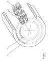
- Figure 1 shows schematically the arrangement in a planetary roller extruder with an internal teeth exhibiting roll cylinder 1 having an external toothing main spindle 2 and arranged therebetween planetary spindles 3.
- the teeth of the spindle is not shown, so that here cylindrical surfaces are shown, not least to to clarify the tip circle diameter D.
- the planetary spindles show longitudinal sections with recesses 4 and longitudinal sections without recesses 5.
- the adjacent planetary spindles are designed to be largely complementary, so that they can interlock.
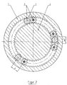
- the sectional view in Figure 2 shows the roll cylinder 1, the main spindle 2 and planetary spindles 3.
- the planetary spindles 3 are arranged in groups 7 and here, for example, again in three groups around the main spindle around.
- the axial distance X of adjacent, here intermeshing planetary spindles 3, is smaller than the tip circle diameter D of a planetary spindle.
- the exemplary arrangement of three adjacent planetary spindles 3 is shown in FIG.
- the lengths with punctures 4 and lengths without punctures 5 of the adjacent planetary spindles 3 are designed to be largely complementary, and interlock. However, it is ensured that always a gap 6 between 0.2 and 5 mm, preferably 1 mm, remains between the spindles.
- the punctures 4 have side edges, which are executed here at an angle ⁇ of 90 ° to the longitudinal axis of the planetary spindle 3. However, it is also conceivable angle ⁇ between 70 ° and 150 °.
- the chosen solution changes the previously known process in the planetary roller extruder. Instead of a longitudinally open chamber between The planetary spindles is an overlap region of the planetary spindles. This divides the available space into two smaller axially open spaces.
- the plasticine forming therein are significantly smaller than those in the known designs, therefore, the risk that unused material enters the space between the spindles, is greatly reduced.
- the kneading is often interrupted and reformatted in the storerooms located within the spindles. Solid parts are thereby well absorbed and dispersed.
- test machine proved the function of this solution in unexpected precision.
- the mechanical energy supply is significantly increased in relation to the comparable length with conventional planetary spindle equipment. This makes the energy input more efficient.
- the length of the machine can be dimensioned to the correct size. This can reduce investment costs and operating costs.
Landscapes
- Engineering & Computer Science (AREA)
- Mechanical Engineering (AREA)
- Processing And Handling Of Plastics And Other Materials For Molding In General (AREA)
- Extrusion Moulding Of Plastics Or The Like (AREA)
- Friction Gearing (AREA)
Description
Die Erfindung bezieht sich auf einen Planetwalzenextruder
- mit einem eine Innenverzahnung aufweisenden Walzenzylinder,
- mit einer eine Außenverzahnung aufweisenden Hauptspindel und
- mit mehreren zwischen Walzenzylinder und Hauptspindel angeordneten, eine Außenverzahnung aufweisenden Planetspindeln.
- with a roller cylinder having an internal toothing,
- with an outer toothing having main spindle and
- arranged with a plurality between roller cylinder and main spindle, an outer toothing having planetary spindles.
Planetwalzenextruder dienen der Herstellung von Kunststoffschmelze, vorzugsweise für die Aufbereitung von empfindlichen Formmassen. Dabei sind mehrere Planetspindeln zwischen einem Walzenzylinder und einer Hauptspindel angeordnet. Beim Antrieb der Hauptspindel wälzen die in Walzenzylinder, Planetspindeln und Hauptspindel eingearbeiteten Verzahnungen aufeinander ab, so daß das zu plastifizierende Kunststoffmaterial einer intensiven Knetwirkung unterworfen wird. Die so hergestellte Kunststoffschmelze hat eine hohe Güte.Planetary roller extruders are used to produce plastic melt, preferably for the preparation of sensitive molding compounds. Several planetary spindles are arranged between a roll cylinder and a main spindle. When driving the main spindle, the teeth integrated in the roll cylinders, planetary spindles and main spindle roll on each other, so that the plastic material to be plasticized is subjected to an intensive kneading action. The plastic melt produced in this way has a high quality.
Der Plastifizierprozeß in einem Planetwalzenextruder findet im Walzenteil statt. Durch Wärmeübertragung und Einleitung von mechanischer Energie wird das zu verarbeitende Material in einen plastischen Zustand überführt, es bildet sich dabei ein Knet.The plasticizing process in a planetary roller extruder takes place in the roller part. By heat transfer and introduction of mechanical energy, the material to be processed is converted into a plastic state, thereby forming a kneading.
Für den Transport der plastifizierten Kunststoffmassen überlagern sich in einem Planetwalzenextruder zwei Fördermechanismen. Einerseits wird das Material durch die Spalte der Verzahnung gepreßt, dadurch wird Energie zum Plastifizieren und Dispergieren eingebracht. Andererseits bildet sich vor den Spalten ein Knet, der durch die Steigung der Verzahnung in Längsrichtung fortbewegt wird. Versuche haben gezeigt, daß ab einer bestimmten Knetgröße unaufgeschmolzene Teilchen längs durch den Extruder gefördert werden, ohne daß jemals eine Überrollung durch einen Spalt stattfindet. Es besteht nun die Möglichkeit, den Extruder entsprechend soweit zu verlängern, bis eine ausreichende Plastifizierung und Homogenisierung stattfindet.For the transport of the plasticized plastic masses, two conveyor mechanisms overlap each other in a planetary roller extruder. On the one hand, the material is pressed through the gaps of the teeth, thereby introducing energy for plasticizing and dispersing. On the other hand, a kneading forms in front of the gaps, which is moved by the pitch of the toothing in the longitudinal direction. Experiments have shown that from a certain kneading size unmelted particles are conveyed longitudinally through the extruder, without ever a rollover through a gap takes place. There is now the possibility of the extruder correspondingly prolonged until sufficient plasticization and homogenization takes place.
Nachteilig bei dieser Lösung ist, daß unnötig viel Energie im Knet dissipiert wird, die auf der zusätzlichen Länge des Extruders durch starke Kühlung wieder abgezogen werden muß. Aus dem jüngeren Stand der Technik sind verschiedene Weiterentwicklungen an Planetwalzenextrudem bekannt, die diese Entwicklungsrichtung verfeinern. Aus der DE 25 21774 ist bekannt, einen Planetwalzenextruder mit einem Stauring zu versehen. Mit diesem Ansatz ist eine Verbesserung möglich, jedoch nicht immer befriedigend.The disadvantage of this solution is that unnecessarily much energy is dissipated in the kneading, which must be deducted on the additional length of the extruder by strong cooling again. Various advances in planetary roller extruders that refine this direction of development are known in the more recent art. From DE 25 21774 it is known to provide a planetary roller extruder with a storage ring. With this approach, an improvement is possible, but not always satisfactory.
Der Erfindung liegt daher die Aufgabe zugrunde, einen Planetwalzenextruder derart weiterzubilden, daß eine unnötig lange Maschinenausführung entbehrlich ist und somit der erhöhte Energieverlust, insbesondere durch Kühlung, vermieden wird, bei gleichzeitig guter Plastifizierung und Dispergierung des Kunststoffmaterials.The invention is therefore the object of developing a planetary roller extruder so that an unnecessarily long machine design is unnecessary and thus the increased energy loss, in particular by cooling, is avoided, at the same time good plasticization and dispersion of the plastic material.
Die Lösung der Aufgabe ist dadurch gekennzeichnet, daß der Achsabstand zwischen zumindest zwei benachbarten Planetspindeln kleiner als der Kopfkreisdurchmesser der Verzahnung der Planetspindeln ist, wobei die Planetspindeln mindestens mit einem Einstich bzw. einer Eindrehung versehen, der bzw. die sich über einen definierten Längenabschnitt der Planetspindel erstreckt. Hierdurch wird es ermöglicht, daß benachbarte Planetspindeln ineinander greifen können und somit der Zwischenraum zwischen den Planetspindeln verkleinert wird, so daß eine verbesserte Materialdurchmischung erreicht wird.The solution of the problem is characterized in that the axial distance between at least two adjacent planetary spindles is smaller than the tip diameter of the teeth of the planetary spindles, wherein the planetary spindles provided at least with a recess or a recess, or over a defined length of the planetary spindle extends. This makes it possible that adjacent planetary spindles can interlock and thus the space between the planetary spindles is reduced, so that an improved material mixing is achieved.
Vorteilhafter Weise sind im montierten Zustand des Planetwalzenextruders sind die Längenbereiche mit Einstichen bzw. Eindrehungen und die Längenbereiche ohne Einstiche bzw. Eindrehungen zueinander weitgehend komplementär ausgebildet. Vorteilhafterweise verbleiben zwischen zwei benachbarten Planetspindeln Spalte, die zwischen 0,2 und 5 mm, vorzugsweise 1 mm, betragen.Advantageously, in the assembled state of the planetary roller extruder are the length ranges with recesses or grooves and the length ranges without recesses or grooves formed largely complementary to each other. Advantageously, gaps remain between two adjacent planetary spindles which are between 0.2 and 5 mm, preferably 1 mm.
Diese segmentweise Aussparung der Planetspindeln ermöglicht ein Ineinanderlaufen der Planetspindeln, ohne daß sich diese dabei berühren. Der Vorteil dieser Ausgestaltung ist, daß alle Oberflächen aufeinander abkämmen. Benachbarte Planetspindeln kämmen mit dem Einstich, die Verzahnung der Planetspindel mit der Hauptspindel und dem Walzenzylinder.This segmental recess of the planetary spindles allows the planetary spindles to run into each other without them touching each other. The advantage of this embodiment is that all surfaces comb each other. Neighboring planetary spindles mesh with the groove, the toothing of the planetary spindle with the main spindle and the roll cylinder.
Die Einstiche bzw. Eindrehungen der Planetspindeln weisen gerade Seitenflanken auf. Gemäß einer vorteilhaften Weiterbildung bilden die Seitenflanken mit der Längsachse der Planetspindel einen Winkel, der zwischen 70° und 150°, vorzugsweise 90°, beträgt.The recesses or grooves of the planetary spindles have straight side edges. According to an advantageous development, the side edges form with the longitudinal axis of the planetary spindle an angle which is between 70 ° and 150 °, preferably 90 °.
Besonders vorteilhaft ist es, wenn der Achsabstand zwischen allen Planetspindeln gleich groß ist. Es ist aber auch denkbar, mehrere Gruppen von Planetspindeln zu bilden, die aus jeweils mindestens zwei Planetspindeln bestehen und um die Hauptspindel herum angeordnet sind.It is particularly advantageous if the axial distance between all planetary spindles is the same. But it is also conceivable to form a plurality of groups of planetary spindles, each consisting of at least two planetary spindles and are arranged around the main spindle around.
Eine besondere Schwierigkeit stellt jedoch die geeignete Form der Einstiche dar. Planetengetriebe und die daran baulich angelehnten Planetwalzenextruder lassen die Plazierung der Planetspindeln nur an bestimmten Positionen zu. Die Anzahl der möglichen Positionen ergibt sich aus der Summe der Zähne des Walzenzylinders plus der Summe der Zähne der Hauptspindel. Der Abstand der Planetspindeln kann also nur dann konstant sein, wenn diese Summe sich durch die Anzahl der Planetspindeln teilen läßt. Da eine gleichmäßige Aufteilung der Planetspindeln für die Prozeßführung des Planetwalzenextruders wichtig ist, wird die Verzahnung so dimensioniert, daß mehrere Planetspindelbestückungen bei gleichen Abständen möglich sind.However, a particular difficulty is the appropriate shape of the punctures. Planetary gear and the planetary geared ajar planetary extruder allow the placement of the planetary spindles only at certain positions. The number of possible positions results from the sum of the teeth of the roll cylinder plus the sum of the teeth of the main spindle. The distance of the planetary spindles can therefore only be constant if this sum can be divided by the number of planetary spindles. Since a uniform distribution of the planetary spindles for the process control of the planetary roller extruder is important, the teeth are dimensioned so that several Planetspindelbestückungen are possible at the same distances.
Sollen die Planetspindeln nun mit konstanten Abständen ineinander kämmen, so ist es zunächst erforderlich, eine geradzahlige Bestückung zu finden, die gleiche Abstände der Planeten untereinander gewährleistet. Sodann sind die typischen Abstände der Planeten auf der Kreisbahn zu ermitteln, um die geeignete Geometrie der Einstiche zu finden. Die Form und Tiefe der Einstiche müssen für jede Extruderbaugröße und Planetenbestückung neu definiert werden.If the planetary spindles now mesh with each other at constant distances, it is first necessary to find an even-numbered component which ensures the same distances between the planets. Then the typical distances of the planets on the circular path are to be determined, in order to find the suitable geometry of the punctures. The shape and depth of the punctures must be redefined for each extruder size and planetary configuration.
Im montierten Zustand und während des Betriebes laufen die losen Spindeln gegen einen Anschlag, den sogenannten Anlaufring. In dieser Situation muß gewährleistet sein, daß benachbarte Planetspindeln sich nicht berühren und somit nicht beschädigt werden. Damit eine derartige Beschädigung der Planetspindeln verhindert wird, ist vorgesehen, die Einstiche bzw. Eindrehungen so zu plazieren, daß zwischen der Projektion zweier Spindeln immer ein gewisses Spiel vorhanden ist.In the mounted state and during operation, the loose spindles run against a stop, the so-called stop ring. In this situation, it must be ensured that adjacent planetary spindles do not touch and are therefore not damaged. To prevent such damage to the planetary spindles, it is provided to place the recesses or recesses so that there is always a certain amount of play between the projection of two spindles.
Weiterhin ist vorgesehen, daß die Planetspindeln unterschiedliche Längen aufweisen.Furthermore, it is provided that the planetary spindles have different lengths.
In den Zeichnungen ist eine schematische Darstellung der Erfindung gezeigt.
- Fig. 1
- zeigt eine perspektivische Darstellung von Teilbereichen eines Planetwalzenextruders, in
- Fig. 2
- ist ein Schnitt durch einen Planetwalzenextruder dargestellt, und
- Fig. 3
- nebeneinander angeordnete Planetspindeln.
- Fig. 1
- shows a perspective view of portions of a planetary roller extruder, in
- Fig. 2
- a section through a planetary roller extruder is shown, and
- Fig. 3
- juxtaposed planetary spindles.
Figur 1 zeigt schematisch die Anordnung in einem Planetwalzenextruder mit einem eine Innenverzahnung aufweisendem Walzenzylinder 1 mit einem eine Außenverzahnung aufweisende Hauptspindel 2 und dazwischen angeordneten Planetspindeln 3. Die Verzahnung der Spindel ist jeweils nicht dargestellt, so daß hier zylindrische Oberflächen gezeigt sind, nicht zuletzt, um den Kopfkreisdurchmesser D zu verdeutlichen.Figure 1 shows schematically the arrangement in a planetary roller extruder with an internal teeth exhibiting roll cylinder 1 having an external toothing
Die Planetspindeln zeigen Längenabschnitte mit Einstichen 4 und Längenabschnitte ohne Einstiche 5 auf. Die benachbarten Planetspindeln sind weitgehendst komplementär ausgeführt, so daß diese ineinander greifen können.The planetary spindles show longitudinal sections with
Die Schnittdarstellung in Figur 2 zeigt den Walzenzylinder 1, die Hauptspindel 2 sowie Planetspindeln 3. Die Planetspindeln 3 sind in Gruppen 7 angeordnet und hier beispielsweise wiederum in drei Gruppen um die Hauptspindel herum. Der Achsabstand X von benachbarten, hier ineinandergreifenden Planetspindeln 3, ist kleiner als der Kopfkreisdurchmesser D einer Planetspindel 3.The sectional view in Figure 2 shows the roll cylinder 1, the
Die beispielhafte Anordnung von drei benachbarten Planetspindeln 3 ist in Figur 3 aufgezeigt. Die Längenabschnitte mit Einstichen 4 und Längenabschnitte ohne Einstiche 5 der benachbarten Planetspindeln 3 sind weitgehendst komplementär ausgeführt, und greifen ineinander ein. Es ist jedoch sichergestellt, daß immer ein Spalt 6 zwischen 0,2 und 5 mm, vorzugsweise 1 mm, zwischen den Spindeln verbleibt. Die Einstiche 4 weisen Seitenflanken auf, die hier in einem Winkel α von 90° zur Längsachse der Planetspindel 3 ausgeführt sind. Es ist jedoch auch ein Winkel α zwischen 70° und 150° denkbar.The exemplary arrangement of three adjacent
Die gewählte Lösung verändert den bisher gekannten Verfahrensprozeß im Planetwalzenextruder. Statt einer längs offenen Kammer zwischen den Planetspindeln befindet sich ein Überlappungsbereich der Planetspindeln. Dieser teilt den zur Verfügung stehenden Raum in zwei kleinere axial offene Räume auf. Die sich darin ausbildenden Knete sind deutlich kleiner als die in den bekannten Ausführungen, daher ist die Gefahr, daß unaufgeschmolzenes Material in dem Raum zwischen den Spindeln zum Austritt gelangt, enorm reduziert.The chosen solution changes the previously known process in the planetary roller extruder. Instead of a longitudinally open chamber between The planetary spindles is an overlap region of the planetary spindles. This divides the available space into two smaller axially open spaces. The plasticine forming therein are significantly smaller than those in the known designs, therefore, the risk that unused material enters the space between the spindles, is greatly reduced.
Durch die segmentweisen wechselseitigen Aussparungen wird der Knet oft unterbrochen und in den sich innerhalb der Spindeln befindlichen Vorratsräumen neu formatiert. Feststoffteile werden dadurch gut aufgenommen und dispergiert.Due to the segment-wise mutual recesses, the kneading is often interrupted and reformatted in the storerooms located within the spindles. Solid parts are thereby well absorbed and dispersed.
Die erfindungsgemäße Umsetzung einer Versuchsmaschine bewies die Funktion dieser Lösung in unerwarteter Prägnanz. Mit der gewählten Geometrie kann bei bestimmten, schwer homogenisierbaren Materialien eine um die Hälfte verkürzte Maschine realisiert werden. Die mechanische Energiezufuhr ist bezogen auf die vergleichbare Länge mit konventioneller Planetspindelbestückung deutlich erhöht. Dadurch wird der Energieeintrag effizienter. Die Länge der Maschine kann auf das richtige Maß dimensioniert werden. Damit können Investitionkosten und Betriebskosten verringert werden.The implementation of a test machine according to the invention proved the function of this solution in unexpected precision. With the chosen geometry, it is possible to realize a half shortened machine for certain materials that are difficult to homogenize. The mechanical energy supply is significantly increased in relation to the comparable length with conventional planetary spindle equipment. This makes the energy input more efficient. The length of the machine can be dimensioned to the correct size. This can reduce investment costs and operating costs.
- 11
- Walzenzylinderrolling cylinders
- 22
- Hauptspindelmain spindle
- 33
- PlanetspindelPlanet spindle
- 44
-
Einstich in Planetspindel 3Groove in
planetary spindle 3 - 55
-
Bereich ohne Einstich 4 in Planetspindel 3Area without
puncture 4 inplanetary spindle 3 - 66
-
Spalt zwischen zwei benachbarten Planetspindeln 3Gap between two adjacent
planetary spindles 3 - 77
-
Gruppe von mindestens zwei Planetspindeln 3Group of at least two
planetary spindles 3
- DD
-
Kopfkreisdurchmesser einer Planetspindel 3Tip diameter of a
planetary spindle 3 - XX
-
Abstand zweier benachbarter Planetspindeln 3Distance between two adjacent
planetary spindles 3
- αα
-
Winkel des Einstichs 4Angle of the
groove 4
Claims (8)
- Planetary gear extruder- with a roller cylinder (1) having inner toothing,- with a main spindle (2) having outer toothing and- with several planetary gear spindles (3) having outer toothing and arranged between roller cylinder (1) and main spindle (2),characterised in that the axial distance (X) between at least two adjacent planetary gear spindles (3) is less than the crown circle diameter (D) of the toothing of the planetary gear spindles (3), wherein the planetary gear spindles (3) have at least one recess or an indentation (4), which extends over a defined longitudinal section of the planetary gear spindle (3).
- Planetary gear extruder according to claim 1, characterised in that in the assembled state of the planetary gear extruder, the longitudinal regions with recesses or indentations (4) and the longitudinal regions without recesses or indentations (4) are designed to be largely complementary to one another.
- Planetary gear extruder according to claim 2, characterised in that the recesses or indentations (4) are designed so that in the assembled state of the planetary gear extruder, in the region of the recesses or indentations (4), gaps (6) between two adjacent planetary gear spindles (3) remain, which are between 0.2 and 5 mm, preferably 1 mm.
- Planetary gear extruder according to one of claims 2 or 3, characterised in that the recesses or indentations (4) have straight side flanks.
- Planetary gear extruder according to claim 4, characterised in that the side flanks form an angle (α), which is between 70° and 150°, preferably 90°, with the longitudinal axis of the planetary gear spindle (3).
- Planetary gear extruder according to one of claims 1 to 5, characterised in that the axial distance (X) between all planetary gear spindles (3) is the same size.
- Planetary gear extruder according to one of claims 1 to 5, characterised in that several groups (7) of planetary gear spindles (3), consisting in each case of at least two planetary gear spindles (3), are arranged around the main spindle (2).
- Planetary gear extruder according to one of claims 1 to 7, characterised in that the planetary gear spindles (3) have different lengths.
Applications Claiming Priority (2)
| Application Number | Priority Date | Filing Date | Title |
|---|---|---|---|
| DE10010807A DE10010807C2 (en) | 2000-03-08 | 2000-03-08 | Planetary roller extruder |
| DE10010807 | 2000-03-08 |
Publications (3)
| Publication Number | Publication Date |
|---|---|
| EP1132191A2 EP1132191A2 (en) | 2001-09-12 |
| EP1132191A3 EP1132191A3 (en) | 2003-11-05 |
| EP1132191B1 true EP1132191B1 (en) | 2007-05-16 |
Family
ID=7633653
Family Applications (1)
| Application Number | Title | Priority Date | Filing Date |
|---|---|---|---|
| EP01104349A Expired - Lifetime EP1132191B1 (en) | 2000-03-08 | 2001-02-23 | Planetary gear extruder |
Country Status (2)
| Country | Link |
|---|---|
| EP (1) | EP1132191B1 (en) |
| DE (2) | DE10010807C2 (en) |
Families Citing this family (3)
| Publication number | Priority date | Publication date | Assignee | Title |
|---|---|---|---|---|
| DE10150006A1 (en) * | 2001-10-11 | 2003-04-17 | Buehler Ag | Ring extruder for processing powders, pellets or flock material has a conveyer screw element with a section which does not intermesh with a screw element on an adjacent screw shaft |
| US20030086331A1 (en) * | 2001-11-08 | 2003-05-08 | Jun-Rong Lin | Extrusion molding machine |
| ATE346738T1 (en) * | 2003-02-09 | 2006-12-15 | Rust & Mitschke Entex | METHOD FOR PROCESSING PET |
Citations (1)
| Publication number | Priority date | Publication date | Assignee | Title |
|---|---|---|---|---|
| DE2521774A1 (en) * | 1975-05-16 | 1976-11-25 | Eickhoff Kleinewefers Kunststo | Thermoplastics extruder suitable for diverse processing conditions - having units of planetary screws around central screw after simple primary screw |
Family Cites Families (2)
| Publication number | Priority date | Publication date | Assignee | Title |
|---|---|---|---|---|
| DE4231232C1 (en) * | 1992-09-18 | 1993-08-19 | Hermann Berstorff Maschinenbau Gmbh, 3000 Hannover, De | High efficiency degassing process for e.g. thermoplastic melts - mixes melt with injected liq. under pressure in extruder, releases pressure to form foam breaks up foam, degasses and spreads into thin film |
| JPH07205256A (en) * | 1993-07-21 | 1995-08-08 | Josef Blach | Multi-screw machine |
-
2000
- 2000-03-08 DE DE10010807A patent/DE10010807C2/en not_active Expired - Lifetime
-
2001
- 2001-02-23 DE DE50112497T patent/DE50112497D1/en not_active Expired - Lifetime
- 2001-02-23 EP EP01104349A patent/EP1132191B1/en not_active Expired - Lifetime
Patent Citations (1)
| Publication number | Priority date | Publication date | Assignee | Title |
|---|---|---|---|---|
| DE2521774A1 (en) * | 1975-05-16 | 1976-11-25 | Eickhoff Kleinewefers Kunststo | Thermoplastics extruder suitable for diverse processing conditions - having units of planetary screws around central screw after simple primary screw |
Also Published As
| Publication number | Publication date |
|---|---|
| DE50112497D1 (en) | 2007-06-28 |
| EP1132191A2 (en) | 2001-09-12 |
| EP1132191A3 (en) | 2003-11-05 |
| DE10010807C2 (en) | 2002-05-02 |
| DE10010807A1 (en) | 2001-10-18 |
Similar Documents
| Publication | Publication Date | Title |
|---|---|---|
| DE4338795C1 (en) | Multi-shaft continuously operating mixing machine for plasticizable masses | |
| EP0160124B1 (en) | Co-rotating twin screw kneader having kneading discs | |
| EP2586584B1 (en) | Worm elements with an improved dispersing effect and low power input | |
| DE4202821C2 (en) | Multi-shaft continuously working mixing and kneading machine for plasticizable masses | |
| DE1502335B2 (en) | SCREW EXTRUSION PRESS FOR THE PROCESSING OF PLASTIC | |
| DE2839552C3 (en) | Nozzle head for the production of plastic granulate | |
| EP3023222B1 (en) | Extruder | |
| DE102008016862A1 (en) | Extruder i.e. two-shaft extruder, has conveyor elements with conveyor sections rotated at angle, where sections comprises axial angle corresponding to maximum of outer dimension of conveyor elements | |
| DE102006010458A1 (en) | Mixing and kneading machine for plastic materials | |
| DE2415896C3 (en) | Screw extruder | |
| EP2335898B1 (en) | Planetary-gear extruder | |
| EP0343549B1 (en) | Steering gear | |
| EP1132191B1 (en) | Planetary gear extruder | |
| DE1922121C3 (en) | Steering gear with changing gear ratio | |
| DE60100970T2 (en) | Device for kneading or mixing materials | |
| DE2802125A1 (en) | Multi-screw homogenising extruder - with intermeshing disc section to restrict axial flow | |
| CH678284A5 (en) | Static mixer assembly requiring no cleaning - in which inner face of tube segments bear ridges which cross each other diagonally with respect to tubular axis | |
| DE102019218637A1 (en) | Spindle drive and method for assembling a spindle drive | |
| DE2051885A1 (en) | Duplex worn screw extruder - allowing transverse adjustment of screw of screw journals and walls for careful plasticising of different mat | |
| EP0074084A1 (en) | Apparatus for continuously melting and mixing plastics | |
| EP0582792B1 (en) | Device for adjusting the clamping force in a clamping device especially in a machine tool vice | |
| DE19943452A1 (en) | Adjustment for lens with axially movable optical element has main and slide settings, thread guide , threaded ring, inner cogging and slide setting thread | |
| DE3839621A1 (en) | Planetary-gear extruder | |
| WO2024083519A1 (en) | Additively manufactured components of an extruder | |
| DE2759074A1 (en) | LOCKING DEVICE FOR POWER STEERING DEVICES AND PROCESS FOR ITS MANUFACTURING |
Legal Events
| Date | Code | Title | Description |
|---|---|---|---|
| PUAI | Public reference made under article 153(3) epc to a published international application that has entered the european phase |
Free format text: ORIGINAL CODE: 0009012 |
|
| AK | Designated contracting states |
Kind code of ref document: A2 Designated state(s): AT BE CH CY DE DK ES FI FR GB GR IE IT LI LU MC NL PT SE TR |
|
| AX | Request for extension of the european patent |
Free format text: AL;LT;LV;MK;RO;SI |
|
| 17P | Request for examination filed |
Effective date: 20030414 |
|
| 17Q | First examination report despatched |
Effective date: 20030617 |
|
| PUAL | Search report despatched |
Free format text: ORIGINAL CODE: 0009013 |
|
| AK | Designated contracting states |
Kind code of ref document: A3 Designated state(s): DE FR GB IT NL |
|
| AX | Request for extension of the european patent |
Extension state: AL LT LV MK RO SI |
|
| AKX | Designation fees paid |
Designated state(s): DE FR GB IT NL |
|
| RTI1 | Title (correction) |
Free format text: PLANETARY GEAR EXTRUDER |
|
| 17Q | First examination report despatched |
Effective date: 20030617 |
|
| GRAP | Despatch of communication of intention to grant a patent |
Free format text: ORIGINAL CODE: EPIDOSNIGR1 |
|
| GRAS | Grant fee paid |
Free format text: ORIGINAL CODE: EPIDOSNIGR3 |
|
| GRAA | (expected) grant |
Free format text: ORIGINAL CODE: 0009210 |
|
| AK | Designated contracting states |
Kind code of ref document: B1 Designated state(s): DE FR GB IT NL |
|
| REG | Reference to a national code |
Ref country code: GB Ref legal event code: FG4D Free format text: NOT ENGLISH |
|
| REF | Corresponds to: |
Ref document number: 50112497 Country of ref document: DE Date of ref document: 20070628 Kind code of ref document: P |
|
| GBT | Gb: translation of ep patent filed (gb section 77(6)(a)/1977) |
Effective date: 20070823 |
|
| ET | Fr: translation filed | ||
| PLBE | No opposition filed within time limit |
Free format text: ORIGINAL CODE: 0009261 |
|
| STAA | Information on the status of an ep patent application or granted ep patent |
Free format text: STATUS: NO OPPOSITION FILED WITHIN TIME LIMIT |
|
| 26N | No opposition filed |
Effective date: 20080219 |
|
| PGFP | Annual fee paid to national office [announced via postgrant information from national office to epo] |
Ref country code: NL Payment date: 20090223 Year of fee payment: 9 |
|
| PGFP | Annual fee paid to national office [announced via postgrant information from national office to epo] |
Ref country code: FR Payment date: 20090217 Year of fee payment: 9 |
|
| REG | Reference to a national code |
Ref country code: NL Ref legal event code: V1 Effective date: 20100901 |
|
| REG | Reference to a national code |
Ref country code: FR Ref legal event code: ST Effective date: 20101029 |
|
| PG25 | Lapsed in a contracting state [announced via postgrant information from national office to epo] |
Ref country code: FR Free format text: LAPSE BECAUSE OF NON-PAYMENT OF DUE FEES Effective date: 20100301 Ref country code: NL Free format text: LAPSE BECAUSE OF NON-PAYMENT OF DUE FEES Effective date: 20100901 |
|
| REG | Reference to a national code |
Ref country code: DE Ref legal event code: R079 Ref document number: 50112497 Country of ref document: DE Free format text: PREVIOUS MAIN CLASS: B29C0047420000 Ipc: B29C0048435000 |
|
| PGFP | Annual fee paid to national office [announced via postgrant information from national office to epo] |
Ref country code: GB Payment date: 20200225 Year of fee payment: 20 Ref country code: IT Payment date: 20200221 Year of fee payment: 20 Ref country code: DE Payment date: 20200229 Year of fee payment: 20 |
|
| REG | Reference to a national code |
Ref country code: DE Ref legal event code: R071 Ref document number: 50112497 Country of ref document: DE |
|
| REG | Reference to a national code |
Ref country code: GB Ref legal event code: PE20 Expiry date: 20210222 |
|
| PG25 | Lapsed in a contracting state [announced via postgrant information from national office to epo] |
Ref country code: GB Free format text: LAPSE BECAUSE OF EXPIRATION OF PROTECTION Effective date: 20210222 |