EP1132180B1 - Portable power tool with an anti-vibration balancing device - Google Patents
Portable power tool with an anti-vibration balancing device Download PDFInfo
- Publication number
- EP1132180B1 EP1132180B1 EP01850044A EP01850044A EP1132180B1 EP 1132180 B1 EP1132180 B1 EP 1132180B1 EP 01850044 A EP01850044 A EP 01850044A EP 01850044 A EP01850044 A EP 01850044A EP 1132180 B1 EP1132180 B1 EP 1132180B1
- Authority
- EP
- European Patent Office
- Prior art keywords
- output shaft
- power tool
- bearing
- balancing
- housing
- Prior art date
- Legal status (The legal status is an assumption and is not a legal conclusion. Google has not performed a legal analysis and makes no representation as to the accuracy of the status listed.)
- Expired - Lifetime
Links
- 230000005540 biological transmission Effects 0.000 claims 2
- 230000008878 coupling Effects 0.000 claims 1
- 238000010168 coupling process Methods 0.000 claims 1
- 238000005859 coupling reaction Methods 0.000 claims 1
- 230000003068 static effect Effects 0.000 description 3
- 230000001627 detrimental effect Effects 0.000 description 1
- 238000007789 sealing Methods 0.000 description 1
Images
Classifications
-
- F—MECHANICAL ENGINEERING; LIGHTING; HEATING; WEAPONS; BLASTING
- F16—ENGINEERING ELEMENTS AND UNITS; GENERAL MEASURES FOR PRODUCING AND MAINTAINING EFFECTIVE FUNCTIONING OF MACHINES OR INSTALLATIONS; THERMAL INSULATION IN GENERAL
- F16F—SPRINGS; SHOCK-ABSORBERS; MEANS FOR DAMPING VIBRATION
- F16F15/00—Suppression of vibrations in systems; Means or arrangements for avoiding or reducing out-of-balance forces, e.g. due to motion
- F16F15/32—Correcting- or balancing-weights or equivalent means for balancing rotating bodies, e.g. vehicle wheels
- F16F15/36—Correcting- or balancing-weights or equivalent means for balancing rotating bodies, e.g. vehicle wheels operating automatically, i.e. where, for a given amount of imbalance, there is movement of masses until balance is achieved
- F16F15/363—Correcting- or balancing-weights or equivalent means for balancing rotating bodies, e.g. vehicle wheels operating automatically, i.e. where, for a given amount of imbalance, there is movement of masses until balance is achieved using rolling bodies, e.g. balls free to move in a circumferential direction
-
- B—PERFORMING OPERATIONS; TRANSPORTING
- B24—GRINDING; POLISHING
- B24B—MACHINES, DEVICES, OR PROCESSES FOR GRINDING OR POLISHING; DRESSING OR CONDITIONING OF ABRADING SURFACES; FEEDING OF GRINDING, POLISHING, OR LAPPING AGENTS
- B24B23/00—Portable grinding machines, e.g. hand-guided; Accessories therefor
- B24B23/02—Portable grinding machines, e.g. hand-guided; Accessories therefor with rotating grinding tools; Accessories therefor
-
- B—PERFORMING OPERATIONS; TRANSPORTING
- B24—GRINDING; POLISHING
- B24B—MACHINES, DEVICES, OR PROCESSES FOR GRINDING OR POLISHING; DRESSING OR CONDITIONING OF ABRADING SURFACES; FEEDING OF GRINDING, POLISHING, OR LAPPING AGENTS
- B24B41/00—Component parts such as frames, beds, carriages, headstocks
- B24B41/007—Weight compensation; Temperature compensation; Vibration damping
-
- B—PERFORMING OPERATIONS; TRANSPORTING
- B25—HAND TOOLS; PORTABLE POWER-DRIVEN TOOLS; MANIPULATORS
- B25F—COMBINATION OR MULTI-PURPOSE TOOLS NOT OTHERWISE PROVIDED FOR; DETAILS OR COMPONENTS OF PORTABLE POWER-DRIVEN TOOLS NOT PARTICULARLY RELATED TO THE OPERATIONS PERFORMED AND NOT OTHERWISE PROVIDED FOR
- B25F5/00—Details or components of portable power-driven tools not particularly related to the operations performed and not otherwise provided for
- B25F5/006—Vibration damping means
Definitions
- the invention relates to a portable power tool, as per the preamble of claim 1, of the type having a rotating output shaft provided with an anti-vibration balancing device in the form of a ball type balancing unit for dampening occurring unbalance in a working implement connected to the output shaft.
- the power tool shown in the drawing figures is a pneumatic angle grinder comprising a housing 10, a rotation motor (not shown), a pressure air inlet valve 11 controlled by a lever 12, and an output shaft 13.
- the output shaft 13 has a forward end 13a journalled in forward bearing 15 and a rear end 13b journalled in a rear bearing 16.
- the output shaft 13 also fitted with a mounting device for a grinding wheel 17, and on the housing 10 there is mounted a safety guard 18 partly surrounding the grinding wheel 17 for protection against incidental grinding wheel desintegration.
- the output shaft 13 is provided with a balancing unit 20 of the type having a number of balls 21 freely movable along a circular race 22 for self adjustment and compensation for imbalance forces in the attached grinding wheel 17.
- the balancing unit 20 which is formed integrally with the output shaft 13 includes a cover washer 23 for sealing off the ball race 22 and maintaining the balls 21 in place.
- the motor is connected to the output shaft 13 via an angle drive comprising a pinion 24 connected to the motor and a bevel gear 25 mounted on the output shaft 13 in a location between the forward bearing 15 and the rear bearing 16.
- the output shaft 13 carries an auxiliary ball type balancer 26 which comprises a ring element 27 defining a circular path for a number of balls 28, and a mounting screw 29 engaging a central threaded bore in the output shaft 13 for securing the ring element 27 to the output shaft 13.
- the auxiliary balancer 26 is located behind the rear shaft bearing 16 and is intended to dampen the dynamic vibration forces not being taken care of by the forward balancing unit 20.
- the forward balancing unit 20 is effective in accomplishing a static balancing of the grinding wheel 17, i.e. generating a counteracting oppositely directed force equal to the imbalance force of the grinding wheel 17, but since this counteracting force is not applied in the same plane as the imbalance force of the grinding wheel 17 there will be a moment acting on the output shaft 13 causing vibrations.
- the grinder has a principal axis of inertia J xx , and the vibratory moment resulting from the imbalance force F 1 developed in the grinding wheel 17 and the counteracting compensating force F 2 provided by the balancing unit 20 at a distance S 1 makes the entire grinder oscillate with respect to the principal axis of inertia J xx .
- the auxiliary balancer 26 is located at the rear end of the output shaft 13, behind the rear bearing 16, to generate a dampening force F 3 acting at a distance S 2 from the compensating force F 2 . Due to the fact that the distance S 2 is much larger than the distance S 1 , the balancing force F 3 needed from the auxiliary balancer 26 is considerably smaller than the force F 1 , because F 1 * S 1 shall equal F 3 * S 2 . See Fig. 3.
- the auxiliary balancer 26 By locating the auxiliary balancer 26 at as long as possible a distance from the balancing unit 20 the required balancing force F 3 and, hence, the size of the auxiliary balancer 26 can be kept small.
Landscapes
- Engineering & Computer Science (AREA)
- Mechanical Engineering (AREA)
- General Engineering & Computer Science (AREA)
- Physics & Mathematics (AREA)
- Acoustics & Sound (AREA)
- Aviation & Aerospace Engineering (AREA)
- Constituent Portions Of Griding Lathes, Driving, Sensing And Control (AREA)
- Harvester Elements (AREA)
- Finish Polishing, Edge Sharpening, And Grinding By Specific Grinding Devices (AREA)
Description
- The invention relates to a portable power tool, as per the preamble of claim 1, of the type having a rotating output shaft provided with an anti-vibration balancing device in the form of a ball type balancing unit for dampening occurring unbalance in a working implement connected to the output shaft.
- In prior art these are known power tools, see for instance US Patent 5,839,950, which are provided with a ball type balancing unit carried at the forward end of the output shaft so as to accomplish an automatic balancing of the vibration forces generated by a grinding wheel attached to the output shaft. By such an arrangement there is obtained a static balancing only, and since there is an inevitable axial distance between the grinding wheel and the balancing unit there will still be dynamic forces causing vibrations with respect to an axis of inertia of the tool. These vibrations cause an uncomfortable and sometimes a detrimental working situation for the tool operator.
- It is a primary object of the invention to accomplish a portable power tool, as per claim 1, in which the static as well as the dynamic vibration forces are counteracted such that the working situation for the operator is improved.
- Further advantages of the invention will appear from the following claims.
- A preferred embodiment of the invention is hereinafter described in detail with reference to the accompanying drawing.
-
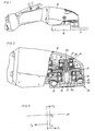
- Fig. 1 shows a side view of a pneumatic angle grinder according to the invention.
- Fig. 2 shows a section through the forward end of the angle grinder shown in Fig. 1.
- Fig. 3 shows a diagrammatic illustration of the balancing forces of the anti-vibration power tool according to the claims.
-
- The power tool shown in the drawing figures is a pneumatic angle grinder comprising a
housing 10, a rotation motor (not shown), a pressureair inlet valve 11 controlled by alever 12, and anoutput shaft 13. Theoutput shaft 13 has aforward end 13a journalled in forward bearing 15 and arear end 13b journalled in arear bearing 16. Theoutput shaft 13 also fitted with a mounting device for agrinding wheel 17, and on thehousing 10 there is mounted asafety guard 18 partly surrounding the grindingwheel 17 for protection against incidental grinding wheel desintegration. - The mounting device which is secured in a concentric threaded
bore 19 in theoutput shaft 13 does not form part of the invention and is therefore not described in further detail. This type of mounting device, however, is described in the above mentioned US Patent 5,839,950. - At its
forward end 13a, theoutput shaft 13 is provided with abalancing unit 20 of the type having a number ofballs 21 freely movable along acircular race 22 for self adjustment and compensation for imbalance forces in the attachedgrinding wheel 17. Thebalancing unit 20 which is formed integrally with theoutput shaft 13 includes acover washer 23 for sealing off theball race 22 and maintaining theballs 21 in place. - The motor is connected to the
output shaft 13 via an angle drive comprising apinion 24 connected to the motor and abevel gear 25 mounted on theoutput shaft 13 in a location between theforward bearing 15 and therear bearing 16. - At its
rear end 13b, theoutput shaft 13 carries an auxiliary ball type balancer 26 which comprises aring element 27 defining a circular path for a number of balls 28, and a mounting screw 29 engaging a central threaded bore in theoutput shaft 13 for securing thering element 27 to theoutput shaft 13. The auxiliary balancer 26 is located behind the rear shaft bearing 16 and is intended to dampen the dynamic vibration forces not being taken care of by theforward balancing unit 20. Theforward balancing unit 20 is effective in accomplishing a static balancing of thegrinding wheel 17, i.e. generating a counteracting oppositely directed force equal to the imbalance force of thegrinding wheel 17, but since this counteracting force is not applied in the same plane as the imbalance force of thegrinding wheel 17 there will be a moment acting on theoutput shaft 13 causing vibrations. - As illustrated in Fig. 3, the grinder has a principal axis of inertia Jxx , and the vibratory moment resulting from the imbalance force F1 developed in the
grinding wheel 17 and the counteracting compensating force F2 provided by thebalancing unit 20 at a distance S1 makes the entire grinder oscillate with respect to the principal axis of inertia Jxx . - To compensate for the vibratory moment, the auxiliary balancer 26 is located at the rear end of the
output shaft 13, behind therear bearing 16, to generate a dampening force F3 acting at a distance S2 from the compensating force F2. Due to the fact that the distance S2 is much larger than the distance S1 , the balancing force F3 needed from the auxiliary balancer 26 is considerably smaller than the force F1, because F1 * S1 shall equal F3 * S2. See Fig. 3. - By locating the auxiliary balancer 26 at as long as possible a distance from the
balancing unit 20 the required balancing force F3 and, hence, the size of the auxiliary balancer 26 can be kept small.
Claims (4)
- Portable power tool with an anti-vibration balancing device, comprising a housing (10), a rotation motor, an output shaft (13) journalled in the housing (10) and having a rear end (13b), and a forward end (13a) provided with a working implement mounting device (19) as well as a ball type balancing unit (20), and a power transmission (24,25) coupling the motor to said output shaft (13),
characterized in that an auxiliary ball type balancer (26) is secured to said rear end (13b) of said output shaft (13) for accomplishing a dynamic balancing of said output shaft (13) at operation with an unbalanced working implement (17) attached to said working implement mounting device (19). - Power tool according to claim 1, wherein said output shaft (13) is journalled in a forward bearing (15) located close to said forward end (13a), and a rear bearing (16) axially spaced from said forward bearing (15), said balancing unit (20) is located in front of said forward bearing (15), whereas said auxiliary balancer (26) is located behind said rear bearing (16).
- Power tool according to claim 1 or 2, wherein said power transmission (24,25) comprises an angle drive including a pinion (24) connected to the motor (11), and a bevel gear (25) secured to said output shaft (13) at a location between said forward bearing (15) and said rear bearing (16).
- Power tool according to claim 3, wherein said forward end (13a) of said output shaft (13) and said balancing unit (20) extends out of said housing (10), and said rear end (13b) of said output shaft (13) and said auxiliary balancer (26) are located inside said housing (10).
Applications Claiming Priority (2)
| Application Number | Priority Date | Filing Date | Title |
|---|---|---|---|
| SE0000761 | 2000-03-08 | ||
| SE0000761A SE0000761L (en) | 2000-03-08 | 2000-03-08 | Hand-held motor-driven tool with a vibration-damping balancing device |
Publications (3)
| Publication Number | Publication Date |
|---|---|
| EP1132180A2 EP1132180A2 (en) | 2001-09-12 |
| EP1132180A3 EP1132180A3 (en) | 2003-11-05 |
| EP1132180B1 true EP1132180B1 (en) | 2005-05-11 |
Family
ID=20278729
Family Applications (1)
| Application Number | Title | Priority Date | Filing Date |
|---|---|---|---|
| EP01850044A Expired - Lifetime EP1132180B1 (en) | 2000-03-08 | 2001-03-08 | Portable power tool with an anti-vibration balancing device |
Country Status (5)
| Country | Link |
|---|---|
| US (1) | US6464572B2 (en) |
| EP (1) | EP1132180B1 (en) |
| JP (1) | JP2001277091A (en) |
| DE (1) | DE60110662T2 (en) |
| SE (2) | SE0000761L (en) |
Families Citing this family (14)
| Publication number | Priority date | Publication date | Assignee | Title |
|---|---|---|---|---|
| DE10242738A1 (en) * | 2002-09-13 | 2005-01-20 | Robert Bosch Gmbh | Hand tool machine, in particular angle grinder |
| DE10357145A1 (en) * | 2003-12-06 | 2005-06-30 | Robert Bosch Gmbh | Hand grinder, mounting flange for a grinding tool and balancing unit |
| US8087977B2 (en) * | 2005-05-13 | 2012-01-03 | Black & Decker Inc. | Angle grinder |
| DE102006030559A1 (en) * | 2006-07-03 | 2008-01-10 | Robert Bosch Gmbh | Electric hand tool |
| DE102006052115A1 (en) * | 2006-11-06 | 2008-05-08 | Robert Bosch Gmbh | Machine tool and tool, each with automatic balancing device |
| US20110081847A1 (en) * | 2009-10-05 | 2011-04-07 | Tai-Her Yang | Motor parallel transmission portable angle grinder |
| JP5566840B2 (en) * | 2010-10-04 | 2014-08-06 | 株式会社マキタ | Rotating tool |
| DE102010043188A1 (en) * | 2010-10-29 | 2012-05-03 | Robert Bosch Gmbh | Discharge safety device |
| CN104395038B (en) * | 2012-07-03 | 2016-12-14 | 阿特拉斯·科普柯工业技术公司 | Electric tool |
| US8966773B2 (en) | 2012-07-06 | 2015-03-03 | Techtronic Power Tools Technology Limited | Power tool including an anti-vibration handle |
| US10818450B2 (en) | 2017-06-14 | 2020-10-27 | Black & Decker Inc. | Paddle switch |
| CN111408999A (en) * | 2019-01-08 | 2020-07-14 | 苏州宝时得电动工具有限公司 | Pressing plate flange and angle grinder with same |
| DE102019103087A1 (en) * | 2019-02-07 | 2020-08-13 | Festool Gmbh | Machine tool with a balancing device |
| US20230278186A1 (en) * | 2022-03-01 | 2023-09-07 | Robert Bosch Gmbh | Self-Aligning Bearing Support Assembly |
Family Cites Families (9)
| Publication number | Priority date | Publication date | Assignee | Title |
|---|---|---|---|---|
| US2164900A (en) * | 1937-08-12 | 1939-07-04 | Cincinnati Grinders Inc | Dynamic balancer for machine tools |
| US2507558A (en) * | 1947-04-12 | 1950-05-16 | Cincinnati Milling Machine Co | Dynamic balancing mechanism |
| GB832048A (en) * | 1958-03-14 | 1960-04-06 | Georg Schafer | Balancing device for rotating bodies |
| SU136214A1 (en) * | 1960-06-02 | 1960-11-30 | Ю.С. Рейбах | Grinding grandma |
| US3692370A (en) * | 1971-09-23 | 1972-09-19 | John R Hasz | Damping means for increasing the minimum dynamic stiffness of a shaft |
| US3731556A (en) * | 1971-11-17 | 1973-05-08 | Cincinnati Milacron Inc | Dynamic balancing apparatus |
| US3885355A (en) * | 1972-02-19 | 1975-05-27 | Ushio Kk | Pneumatically driven grinder |
| US5111713A (en) * | 1989-12-18 | 1992-05-12 | International Business Machines Corporation | Dynamically balanced rotary unit |
| SE510981C2 (en) * | 1996-05-07 | 1999-07-19 | Atlas Copco Tools Ab | Portable grinding machine with interchangeable wear part |
-
2000
- 2000-03-08 SE SE0000761A patent/SE0000761L/en not_active IP Right Cessation
- 2000-03-08 SE SE516370D patent/SE516370C2/en not_active IP Right Cessation
-
2001
- 2001-03-07 US US09/801,281 patent/US6464572B2/en not_active Expired - Lifetime
- 2001-03-08 JP JP2001065008A patent/JP2001277091A/en active Pending
- 2001-03-08 EP EP01850044A patent/EP1132180B1/en not_active Expired - Lifetime
- 2001-03-08 DE DE60110662T patent/DE60110662T2/en not_active Expired - Lifetime
Also Published As
| Publication number | Publication date |
|---|---|
| SE0000761D0 (en) | 2000-03-08 |
| SE516370C2 (en) | 2002-01-08 |
| JP2001277091A (en) | 2001-10-09 |
| DE60110662D1 (en) | 2005-06-16 |
| EP1132180A3 (en) | 2003-11-05 |
| US20010031616A1 (en) | 2001-10-18 |
| SE0000761L (en) | 2001-09-09 |
| US6464572B2 (en) | 2002-10-15 |
| EP1132180A2 (en) | 2001-09-12 |
| DE60110662T2 (en) | 2006-01-19 |
Similar Documents
| Publication | Publication Date | Title |
|---|---|---|
| US6464572B2 (en) | Portable power tool with an anti-vibration balancing device | |
| US4817738A (en) | Portable handheld motor-driven tool | |
| US5125189A (en) | Vibration damped hand held rotary grinding machine | |
| US5077942A (en) | Vibration damped hand held rotary grinding machine | |
| US20090068936A1 (en) | Electric hand-held power tool | |
| US20110011608A1 (en) | Power tool | |
| US20040016133A1 (en) | Adjustable antivibration system, in particular for a hand-held work machine | |
| US10828743B2 (en) | Oscillating electric power tool with balanced armature shaft | |
| SE518103C2 (en) | Water pump at portable cutting machine | |
| GB2443560A (en) | Automatic rotation balancing device. | |
| WO2011152135A1 (en) | Portable power tool | |
| US4467753A (en) | Vibration dampener on engine shaft | |
| EP0675781A1 (en) | A vibration-free grinding machine | |
| CN221248216U (en) | Angle grinder with vibration reduction mechanism | |
| GB2399784A (en) | Electric tool with air discharge bore in gear unit housing | |
| CN101312806A (en) | Portable grinder with wheel guard and auxiliary handle | |
| JP7681409B2 (en) | Impact tools | |
| JP7788341B2 (en) | Power tool handles | |
| JP2003137116A (en) | Steering column | |
| JP4202978B2 (en) | Brush cutter | |
| JPH0644338Y2 (en) | Anti-vibration device for brush cutter | |
| JP3007033B2 (en) | Machine tool seal structure | |
| US20240397861A1 (en) | Handheld work apparatus | |
| CN119927761A (en) | Angle grinder with vibration reduction mechanism | |
| JP4194032B2 (en) | Anti-vibration coil spring holder |
Legal Events
| Date | Code | Title | Description |
|---|---|---|---|
| PUAI | Public reference made under article 153(3) epc to a published international application that has entered the european phase |
Free format text: ORIGINAL CODE: 0009012 |
|
| AK | Designated contracting states |
Kind code of ref document: A2 Designated state(s): AT BE CH CY DE DK ES FI FR GB GR IE IT LI LU MC NL PT SE TR |
|
| AX | Request for extension of the european patent |
Free format text: AL;LT;LV;MK;RO;SI |
|
| PUAL | Search report despatched |
Free format text: ORIGINAL CODE: 0009013 |
|
| AK | Designated contracting states |
Kind code of ref document: A3 Designated state(s): AT BE CH CY DE DK ES FI FR GB GR IE IT LI LU MC NL PT SE TR |
|
| AX | Request for extension of the european patent |
Extension state: AL LT LV MK RO SI |
|
| RIC1 | Information provided on ipc code assigned before grant |
Ipc: 7F 16F 15/36 B Ipc: 7F 16F 15/00 B Ipc: 7B 25F 5/00 A Ipc: 7B 24B 41/00 B Ipc: 7B 24B 23/02 B |
|
| 17P | Request for examination filed |
Effective date: 20040408 |
|
| AKX | Designation fees paid |
Designated state(s): DE FR GB IT |
|
| GRAP | Despatch of communication of intention to grant a patent |
Free format text: ORIGINAL CODE: EPIDOSNIGR1 |
|
| GRAP | Despatch of communication of intention to grant a patent |
Free format text: ORIGINAL CODE: EPIDOSNIGR1 |
|
| GRAS | Grant fee paid |
Free format text: ORIGINAL CODE: EPIDOSNIGR3 |
|
| GRAA | (expected) grant |
Free format text: ORIGINAL CODE: 0009210 |
|
| AK | Designated contracting states |
Kind code of ref document: B1 Designated state(s): DE FR GB IT |
|
| REG | Reference to a national code |
Ref country code: GB Ref legal event code: FG4D |
|
| REG | Reference to a national code |
Ref country code: IE Ref legal event code: FG4D |
|
| REF | Corresponds to: |
Ref document number: 60110662 Country of ref document: DE Date of ref document: 20050616 Kind code of ref document: P |
|
| PLBE | No opposition filed within time limit |
Free format text: ORIGINAL CODE: 0009261 |
|
| STAA | Information on the status of an ep patent application or granted ep patent |
Free format text: STATUS: NO OPPOSITION FILED WITHIN TIME LIMIT |
|
| ET | Fr: translation filed | ||
| 26N | No opposition filed |
Effective date: 20060214 |
|
| REG | Reference to a national code |
Ref country code: DE Ref legal event code: R082 Ref document number: 60110662 Country of ref document: DE Representative=s name: PATENTANWAELTE OLBRICHT, BUCHHOLD, KEULERTZ PA, DE |
|
| REG | Reference to a national code |
Ref country code: FR Ref legal event code: PLFP Year of fee payment: 16 |
|
| REG | Reference to a national code |
Ref country code: FR Ref legal event code: PLFP Year of fee payment: 17 |
|
| REG | Reference to a national code |
Ref country code: FR Ref legal event code: PLFP Year of fee payment: 18 |
|
| PGFP | Annual fee paid to national office [announced via postgrant information from national office to epo] |
Ref country code: IT Payment date: 20190322 Year of fee payment: 19 Ref country code: FR Payment date: 20190325 Year of fee payment: 19 Ref country code: DE Payment date: 20190327 Year of fee payment: 19 |
|
| PGFP | Annual fee paid to national office [announced via postgrant information from national office to epo] |
Ref country code: GB Payment date: 20190404 Year of fee payment: 19 |
|
| REG | Reference to a national code |
Ref country code: DE Ref legal event code: R119 Ref document number: 60110662 Country of ref document: DE |
|
| PG25 | Lapsed in a contracting state [announced via postgrant information from national office to epo] |
Ref country code: DE Free format text: LAPSE BECAUSE OF NON-PAYMENT OF DUE FEES Effective date: 20201001 Ref country code: FR Free format text: LAPSE BECAUSE OF NON-PAYMENT OF DUE FEES Effective date: 20200331 |
|
| GBPC | Gb: european patent ceased through non-payment of renewal fee |
Effective date: 20200308 |
|
| PG25 | Lapsed in a contracting state [announced via postgrant information from national office to epo] |
Ref country code: GB Free format text: LAPSE BECAUSE OF NON-PAYMENT OF DUE FEES Effective date: 20200308 |
|
| PG25 | Lapsed in a contracting state [announced via postgrant information from national office to epo] |
Ref country code: IT Free format text: LAPSE BECAUSE OF NON-PAYMENT OF DUE FEES Effective date: 20200308 |