EP1131902B1 - Variable loop gain in double loop power control systems - Google Patents
Variable loop gain in double loop power control systems Download PDFInfo
- Publication number
- EP1131902B1 EP1131902B1 EP99971597A EP99971597A EP1131902B1 EP 1131902 B1 EP1131902 B1 EP 1131902B1 EP 99971597 A EP99971597 A EP 99971597A EP 99971597 A EP99971597 A EP 99971597A EP 1131902 B1 EP1131902 B1 EP 1131902B1
- Authority
- EP
- European Patent Office
- Prior art keywords
- signal
- noise ratio
- threshold
- loop gain
- fading rate
- Prior art date
- Legal status (The legal status is an assumption and is not a legal conclusion. Google has not performed a legal analysis and makes no representation as to the accuracy of the status listed.)
- Expired - Lifetime
Links
Images


Classifications
-
- H—ELECTRICITY
- H04—ELECTRIC COMMUNICATION TECHNIQUE
- H04W—WIRELESS COMMUNICATION NETWORKS
- H04W52/00—Power management, e.g. TPC [Transmission Power Control], power saving or power classes
- H04W52/04—TPC
-
- H—ELECTRICITY
- H04—ELECTRIC COMMUNICATION TECHNIQUE
- H04W—WIRELESS COMMUNICATION NETWORKS
- H04W52/00—Power management, e.g. TPC [Transmission Power Control], power saving or power classes
- H04W52/04—TPC
- H04W52/06—TPC algorithms
- H04W52/12—Outer and inner loops
-
- H—ELECTRICITY
- H04—ELECTRIC COMMUNICATION TECHNIQUE
- H04W—WIRELESS COMMUNICATION NETWORKS
- H04W52/00—Power management, e.g. TPC [Transmission Power Control], power saving or power classes
- H04W52/04—TPC
- H04W52/18—TPC being performed according to specific parameters
- H04W52/20—TPC being performed according to specific parameters using error rate
-
- H—ELECTRICITY
- H04—ELECTRIC COMMUNICATION TECHNIQUE
- H04W—WIRELESS COMMUNICATION NETWORKS
- H04W52/00—Power management, e.g. TPC [Transmission Power Control], power saving or power classes
- H04W52/04—TPC
- H04W52/18—TPC being performed according to specific parameters
- H04W52/22—TPC being performed according to specific parameters taking into account previous information or commands
- H04W52/225—Calculation of statistics, e.g. average, variance
-
- H—ELECTRICITY
- H04—ELECTRIC COMMUNICATION TECHNIQUE
- H04W—WIRELESS COMMUNICATION NETWORKS
- H04W52/00—Power management, e.g. TPC [Transmission Power Control], power saving or power classes
- H04W52/04—TPC
- H04W52/18—TPC being performed according to specific parameters
- H04W52/22—TPC being performed according to specific parameters taking into account previous information or commands
- H04W52/228—TPC being performed according to specific parameters taking into account previous information or commands using past power values or information
-
- H—ELECTRICITY
- H04—ELECTRIC COMMUNICATION TECHNIQUE
- H04W—WIRELESS COMMUNICATION NETWORKS
- H04W52/00—Power management, e.g. TPC [Transmission Power Control], power saving or power classes
- H04W52/04—TPC
- H04W52/18—TPC being performed according to specific parameters
- H04W52/24—TPC being performed according to specific parameters using SIR [Signal to Interference Ratio] or other wireless path parameters
-
- H—ELECTRICITY
- H04—ELECTRIC COMMUNICATION TECHNIQUE
- H04W—WIRELESS COMMUNICATION NETWORKS
- H04W52/00—Power management, e.g. TPC [Transmission Power Control], power saving or power classes
- H04W52/04—TPC
- H04W52/30—TPC using constraints in the total amount of available transmission power
- H04W52/36—TPC using constraints in the total amount of available transmission power with a discrete range or set of values, e.g. step size, ramping or offsets
Definitions
- the present invention relates to wireless communication systems. More specifically, the present invention relates to a novel and improved system and method of power control in a wireless communications system.
- Wireless communication networks are enjoying notable popularity in all aspects of business, industry and personal life. As such, portable, hand-held communication devices have experienced widespread growth in recent years. Portable devices such as cellular phones are now commonplace with business and personal users alike. Additionally, advanced systems, such as satellite communications systems using portable, hand held and mobile phones, are currently being deployed.
- signals are subject to fading. Fading occurs when environmental factors diminish the power of a signal during its transmission from transmitter to receiver.
- One measurement that quantifies fading is the signal-to-noise ratio (SNR) of the received signal as measured at the receiver.
- SNR signal-to-noise ratio
- Systems have been developed to adjust the transmitted power of the signal to compensate for fading.
- Single-loop power control.
- the receiver monitors the SNR of the received signal and sends commands to the transmitter to adjust the transmitted power so as to maintain a specified "threshold" SNR at the receiver.
- Conventional single-loop power control systems generally employ two or three types of such commands.
- One type of command instructs the transmitter to increase the transmitted power.
- Another type of command instructs the transmitter to decrease the transmitted power.
- the amount by which the transmitted power is increased or decreased in response to such a command is referred to as the "gain" of the loop.
- a third type of command is used to instruct the transmitter to maintain the transmitted power at the current level.
- Single-loop power control works well in an environment with slow fading.
- slow fading there is no substantial fading during the time required for a power control command to reach the transmitter and the resulting signal-to-noise ratio to be measured at the receiver, known as the "period" of the loop.
- One example of a slow fading environment is one having only thermal noise as signal interference.
- the adequacy of the threshold SNR can be quantified by the ratio of information bits received in error to the total number of bits received. This ratio is generally computed repeatedly for each frame. The ratio thus computed is known as the "frame error rate” (FER) of the signal.
- FER frame error rate
- One type of system developed to address this problem is known as a "double-loop" power control system.
- the single-loop power control system described above is used as the "inner” loop.
- the SNR threshold used by the inner loop is modified by an "outer" loop based on the FER of the received signal. For example, when the FER rises above a predetermined FER threshold, the threshold SNR is increased by a fixed, predetermined amount. This process continues until the FER falls below the FER threshold.
- variable gain systems can only be adjusted based on the signal quality threshold, which does not account for the fade rate of the signals.
- both prior fixed gain systems and variable gain systems are not fully responsive to the communications environment. What is needed is a double-loop power control system where the inner-loop gain can be varied to suit the speed of the fading.
- the present invention is an apparatus and method for adjusting the power of a signal sent by a transmitter to a receiver to compensate for fading in a wireless communications system.
- the method includes the steps of measuring, at a first station, a signal-to-noise ratio of a signal transmitted by a second station, the signal comprising a plurality of frames; adjusting a transmitted signal power of the signal as a function of a loop gain, the signal-to-noise ratio, and a signal-to-noise ratio threshold; measuring, at the first station, a signal quality of the received signal; adjusting the signal-to-noise ratio threshold as a function of the signal quality and a signal quality threshold by increasing the signal-to-noise ratio threshold when a current frame has an error and a predetermined number of previous frames have no errors with a preselected minimum period between increases; and decreasing said signal-to-noise ratio threshold otherwise; measuring, at the first station, a fading rate of the signal; and adjusting the loop gain as a
- the method includes the steps of measuring, at a first station, a signal-to-noise ratio of a signal transmitted by a second station, the signal comprising a plurality of frames; adjusting a transmitted signal power of the signal as a function of a loop gain, the signal-to-noise ratio, and a signal-to-noise ratio threshold; measuring, at the first station, a signal quality of the received signal; adjusting the signal-to-noise ratio threshold as a function of the signal quality and a signal quality threshold by increasing the signal-to-noise ratio threshold when a current frame has an error and a predetermined number of previous frames have no errors with a preselected minimum period between increases; and decreasing said signal-to-noise ratio threshold otherwise; measuring, at the second station, a fading rate of a further signal transmitted by the first station; and adjusting the loop gain as a function of the fading rate and a fading rate threshold.
- One advantage of the present invention is that it mitigates the effects of fast fading.
- the present invention is an apparatus and method for double loop power control in a wireless communications system.
- the present invention operates within a code-division multiple-access (CDMA) communications system.
- Power control loops operating within such systems are disclosed in U.S. Patent Application Serial Nos. 09/164,383 , entitled “System and Method for Selecting Power Control Modes" (Atty. docket PA667) and 09/ 64,384 , entitled “System and Method for Optimized Power Control" (Atty. docket PA668).
- Other examples of techniques for power control in such communication systems are found in U. S. Patent Nos. 5,383,219 , entitled "Fast.
- the present invention can be implemented in any wireless communication system, especially one in which it is desirable to control the amount of power provided by a transmitter.
- Such environments include, without limitation, cellular communication systems, personal communication systems, satellite communication systems, and many others.
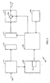
- FIG. 1 is a diagram illustrating an exemplary communication system 100.
- system 100 has two transceivers 102 and 104.
- Transceiver 102 has a transmitter 106 and a receiver 108.
- Transceiver 104 has a transmitter 112 and a receiver 110.
- channel 122 is a wireless link.
- channel 122 includes one or more relay satellites.
- Channel 122 is a two-way channel that includes a "forward" signal 116 and a "reverse" signal 118.
- channel 122 is a packetized data path in which the data is transmitted in data packets. This is often the case where the information is in the form of digital data. In other environments, analog data is modulated onto a carrier and transmitted across channel 122.
- transceiver 102 is a hand-held or mobile cellular telephone and transceiver 104 is a base station at the local cell site that is providing service in the phone's current area.
- transceiver 102 is a hand-held, mobile, or fixed transceiver (for example, a satellite telephone) and transceiver 104 is located in a terrestrial gateway.
- a satellite is used to relay signals between the transceivers 102 and 104 over channel 122.
- the present invention is a system and method for adjusting transmitted signal power to compensate for fast fading in a wireless communications system.
- fast fading several signal fades occur during a single outer-loop period.
- the outer loop is ineffective to mitigate fast fading.
- fast fading is often superimposed upon a slower fading trend.
- the inventors have found that one good solution to the fast fading case is to ignore the fast (high-frequency) component of the fading and instead track any slower (low-frequency) components of the fading.
- the system when fast fading is detected, the system attempts to track the underlying slow fading rather than attempting to track the fast fading. In a preferred embodiment of the present invention, this is accomplished by using a small inner loop gain.
- FIG. 2 is a block diagram illustrating transceiver 102 in greater detail.
- Transceiver 102 includes transmitter 106, receiver 108, a measurement element 202, a processor 204, a memory 206, a data destination 210 and a data source 212.
- receiver 108 receives signal 116 and passes it to data destination 210.
- Data destination 210 can be any element that makes use of the data, such as a CODEC, MODEM, digital signal processor, and the like.
- Receiver 108 may performs certain tasks, such as demodulation, on signal 116, as is well-known in the art.
- Measurement element 202 makes certain measurements of the characteristics of signal 116, as is described in detail below. For example, these measurements include measurements of SNR, signal quality based on the presence of one or more error events (such as FER) and fading rate (FR).
- measurement element 202 includes a SNR measurement circuit 214 and a frame error measurement circuit 216.
- SNR measurement circuit 214 obtains measurements of the SNR of received signal 116.
- Frame error measurement circuit 216 obtains measurements of the error rate, or one or more other error events, of received signal 116. Circuits that accomplish these functions are well-known in the relevant arts.
- These measurements are passed to a processor 204, which can be any processor known in the art or developed hereafter.
- Processor 204 employs a memory 206 for storage of data, such as the SNR, FER, and FR measurements, and other values, such as thresholds for comparison with these measurements.
- Data source 212 generates data for transmission.
- Data source 212 can include elements such as CODECs, MODEMS, digital signal processors, and the like, as is well-known in the art.
- Transmitter 106 receives data from data source 212 and performs such tasks as modulation.
- Processor 204 may be implemented using hardware, software or a combination thereof and may be implemented as a computer system or other processing system. In one embodiment, processor 204 is implemented as one or more computer systems. In another embodiment, processor 204 is implemented primarily in hardware using, for example, hardware components such as application specific integrated circuits (ASICs). Implementation of a hardware state machine so as to perform the functions described herein will be apparent to persons skilled in the relevant art(s). In yet another embodiment, processor 204 is implemented using a combination of both hardware and software.
- ASICs application specific integrated circuits
- FIG. 3 is a block diagram illustrating transceiver 104 in greater detail.
- Transceiver 104 includes transmitter 112, receiver 110, a measurement element 302, a processor 304, a memory 306, a data destination 310 and a data source 312.
- receiver 110 receives signal 118 and passes it to data destination 310.
- Data destination 310 can be any element that makes use of the data, such as a CODEC, MODEM, digital signal processor, and the like.
- Receiver 110 may perform certain tasks, such as demodulation, on signal 118, as is well-known in the art.
- Measurement element 302 makes certain measurements of the characteristics of signal 118, as is described in detail below. For example, these measurements include measurement of fading rate (FR).
- measurement element 302 includes a SNR measurement circuit 314.
- SNR measurement circuit 314 obtains measurements of the SNR of received signal 118. Circuits that accomplish this function are well-known in the relevant arts. These measurements are passed to transmitter 112 and/or data source 312 for transmission as part of signal 116. These measurements are passed to processor 304, which can be any processor known in the art or developed hereafter.
- Processor 304 employs a memory 306 for storage of data, such as the measurements, and other values, such as thresholds for comparison with these measurements.
- Data source 312 generates data for transmission.
- Data source 312 can include elements such as CODECs, MODEMS, digital signal processors, and the like, as is well-known in the art.
- Transmitter 112 receives data from data source 312 and performs such tasks as modulation before transmitting signal 116.
- Transmitter 112 also includes a variable-gain amplifier 308 for amplifying the power of the signal prior to transmission to produce signal 116. The gain of amplifier 308 is controlled by processor 304.
- FIGS. 4-6 are flowcharts depicting the operation of the present invention according to a preferred embodiment.
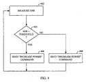
- FIG. 4 depicts the operation of the inner power control loop of the present invention.
- the function of the inner power control loop is to adjust the signal power transmitted by transmitter 112.
- the transmitted signal power is adjusted according to the level of signal power received at receiver 108, as described below.
- Transmitter 112 transmits signal 116 over channel 122.
- Signal 116 is received by receiver 108.
- the process begins with the measurement by measurement element 202 of the power of signal 116, as shown in step 402.
- measurement element 202 measures the signal-to-noise ratio (SNR) of signal 116. More specifically, the present invention measures the quantity Eb/No, where Eb is energy per bit and No is noise density in units of power/cycle. Of course, other measures of signal power can be used without departing from the scope of the present invention.
- SNR is-measured for every frame of received data.
- a predetermined SNR level referred to as the "SNR threshold” is associated with receiver 108.
- the SNR threshold represents the minimum SNR at which signals should be received by receiver 108 in order to ensure data quality.
- the SNR threshold can be selected according to methods that are well-known in the relevant arts. One such method is to select a SNR that will keep data errors under a certain percentage, such as one percent.
- receiver 108 compares the SNR measured in step 402 to the SNR threshold.
- transmitter 106 of transceiver 102 transmits an "increase power" command to transceiver 104, as shown in step 406.
- the command is transmitted as part of signal 118 over channel 122.
- transmitter 112 increases the signal power of the signal 116 by a predetermined amount, referred to as the "gain" of the inner loop, or “inner loop gain.”
- the value of the inner loop gain, and the value of the signal gain applied by amplifier 308, are stored in memory 306. The value of the signal gain is manipulated by processor 304.
- transmitter 106 of transceiver 102 transmits a "decrease power" command to transceiver 104, as shown in step 408.
- transmitter 112 decreases the signal power of signal 116 by the inner loop gain. In either case, the process resumes at step 402.
- FIG. 5 depicts the operation of the outer power control loop of the present invention (also referred to as the "outer loop").
- the function of the outer power control loop is to adjust the SNR threshold of receiver 108.
- the SNR threshold is adjusted according to the quality of the received signal.
- the quality of the signal is considered not only for the current frame, but also for a certain number of previous frames.
- the measure of signal quality used is the presence of one or more error events, for example using a frame error rate (FER).
- FER frame error rate
- other measures of signal quality such as parity checks, can be used without-departing from the scope of the present invention.
- other methods of evaluating the signal quality history such as averages and weighted averages, can be used.
- Burst errors are characterized by short duration. In general, the duration of a burst error is less than the inner loop period. Therefore, the inner loop cannot compensate for these errors. For this reason, it is desirable to isolate the inner loop from the effects of burst errors. Burst errors are also characterized by errors in multiple consecutive frames. The outer loop uses this characteristic to detect burst errors. When the outer loop detects errors in multiple consecutive frames, it determines that a burst error has occurred. When a burst error is detected, the outer loop does not increase the SNR threshold of the inner loop. The outer loop increases the SNR threshold of the inner loop only in response to non-burst type errors, thereby isolating the inner loop from burst errors.
- the process begins by making measurements of a quantity indicative of the presence of errors, for example FER, as shown in step 502.
- the process determines whether or not errors are present in the current frame using the results of such measurements, as shown in step 504. If no errors are present in the current frame, as indicated by the "N" branch in step 504, then transceiver 102 decreases the SNR threshold by a predetermined amount, as shown in step 506. However, if errors are present in the current frame, as indicated by the "Y" branch in step 504, then the quality history of the received signal is reviewed, as shown in step 508.
- the error history comprises a predetermined number of previous frames N.
- the error history can be selected in other ways without departing from the scope of the present invention.
- the error history is preserved in memory 206. If any of the previous N frames contain an error, then transceiver 102 decreases the SNR threshold by the outer loop gain, as shown in step 506, subject to a desired frame or timing delay as discussed below.
- transceiver 102 increases the SNR threshold, as shown in step 510.
- two change values are employed: one for decreasing the SNR threshold, and the other for increasing the SNR threshold.
- the change value for decreasing the SNR threshold is small, so that the SNR threshold, and through the action of the inner loop, the transmitted signal power, is gradually reduced in error-free environments.
- the change value for increasing the SNR threshold is large, so that the SNR threshold, and through the action of the inner loop, the transmitted signal power, is quickly increased in error-prone environments.
- an initial increase in the SNR threshold occurs when encountering a frame error after a certain number of error free frames as just described, but for a preselected number of frames Z after this adjustment no additional increase is allowed to occur. That is, the detection or not of frame errors does not provide a mechanism for selecting further increases in the threshold value until Z frames or frame periods have occurred after an increase. This is shown by step 512 which is positioned between quality history checking step 508 and threshold adjustment step 510.
- step 512 a check is made to see whether or not Z data frames have been processed since the last SNR threshold increase.
- the frame count for this processing step is initially set equal to Z so that the first time an adjustment is requested it is made, as shown by set/reset step 514. Subsequent adjustments will then be determined from the frame count.
- the SNR threshold is allowed to decrease by a fairly small amount, or at a low rate, for each of the Z frames, as shown in step 516. That is, during or at the end of each frame period the SNR threshold level is decremented or decreased by a small percentage or amount, say on the order of 0.004 dB. Those skilled in the art will readily recognize that other amounts may be used, as desired. Processing then returns to step 502 where measurements continue and so forth. Once the requisite number of preselected frames Z have been reached, the SNR threshold is again increased in step 510 (or decreased in step 506) instead of decremented in step 516. Once an SNR threshold increase occurs, the frame count used in step 512 is reset to zero and the counting process beings anew until Z frames have again passed.
- Z is selected to be six frames after the frame generating or triggering an increase in SNR threshold, during which no additional increase occurs and a gradual decrease is implemented.
- FIG. 6 is a flowchart depicting the operation of a variable-gain inner double-loop power control loop according to a preferred embodiment of the present invention.
- receiver 108 measures a fading rate of a signal received from transceiver 104A.
- receiver 108 measures the SNR of the received signal several times over the course of each frame to produce a series of measurements. This series is applied to a high-pass filter to detect rapid changes in SNR, which indicate the presence of fast fading.
- the output of the high-pass filter referred to as the "fading rate” is compared to a predetermined fading rate threshold, as shown in step 604.
- the inner-loop gain is set to a first predetermined gain level G1, as shown in step 606.
- the inner-loop gain is set to a second predetermined gain level G2, as shown in step 608. In either case, processing resumes at step 602.
- first gain level G1 is much larger than second gain level G2.
- the inner-loop gain applied during fast fading is much less than the inner-loop gain applied otherwise. The result is that, during fast fading, the power control loop does not attempt to track the rapid signal power level fluctuations caused by the fast fading, but rather tracks the slower power level fluctuations caused by slower fading.
- G1 is approximately 0.5 dB
- G2 is approximately 0.1 dB.
- the user terminal detects fast fading in the signal transmitted from the gateway to the user terminal.
- the user terminal reports the fast fading condition to the gateway, which responds by adjusting the inner-loop gain of the power control loop.
- fast fading in signal 116 is detected by transceiver 102 in step 604.
- Transceiver 102 detects fast fading in signal 116 by evaluating fluctuations in its SNR, as described in detail above.
- Fast fading is detected by evaluating the SNR.
- Transmitter 106 then transmits a command to receiver 110 to adjust the inner-loop gain. In accordance with that command, transceiver 104 adjusts the inner-loop gain in steps 606 and 608.
- the gateway infers that fast fading exists in the signal transmitted from the gateway to the user terminal by detecting fast fading of a signal transmitted by the user terminal to the gateway.
- the fading rate of signal 116 is inferred by transceiver 104 by evaluating the SNR fluctuations in signal 118 in steps 602 and 604, as described in detail above. Transceiver 104 then adjusts the inner-loop gain in steps 606 and 608 based on that evaluation.
Abstract
Description
- The present invention relates to wireless communication systems. More specifically, the present invention relates to a novel and improved system and method of power control in a wireless communications system.
- Wireless communication networks are enjoying notable popularity in all aspects of business, industry and personal life. As such, portable, hand-held communication devices have experienced widespread growth in recent years. Portable devices such as cellular phones are now commonplace with business and personal users alike. Additionally, advanced systems, such as satellite communications systems using portable, hand held and mobile phones, are currently being deployed.
- In wireless communication systems, signals are subject to fading. Fading occurs when environmental factors diminish the power of a signal during its transmission from transmitter to receiver. One measurement that quantifies fading is the signal-to-noise ratio (SNR) of the received signal as measured at the receiver. Systems have been developed to adjust the transmitted power of the signal to compensate for fading. One such system is known as "single-loop" power control.
- In a single-loop power control system, the receiver monitors the SNR of the received signal and sends commands to the transmitter to adjust the transmitted power so as to maintain a specified "threshold" SNR at the receiver. Conventional single-loop power control systems generally employ two or three types of such commands. One type of command instructs the transmitter to increase the transmitted power. Another type of command instructs the transmitter to decrease the transmitted power. The amount by which the transmitted power is increased or decreased in response to such a command is referred to as the "gain" of the loop. In some systems, a third type of command is used to instruct the transmitter to maintain the transmitted power at the current level.
- Single-loop power control works well in an environment with slow fading. In slow fading, there is no substantial fading during the time required for a power control command to reach the transmitter and the resulting signal-to-noise ratio to be measured at the receiver, known as the "period" of the loop. One example of a slow fading environment is one having only thermal noise as signal interference.
- However, in a signal environment with medium-speed fading, single-loop power control is inadequate. In medium-speed fading, there is substantial fading during a single loop period. One example of a medium-speed fading environment is where the transmitter or receiver is moving rapidly past stationary obstructions, causing rapid changes in signal attenuation. In such a medium-speed fading environment, the threshold SNR may be insufficient to ensure signal quality. This is because the loop is too slow to respond to the rapid variations in the SNR of the received signal.
- In digital communication systems, the adequacy of the threshold SNR can be quantified by the ratio of information bits received in error to the total number of bits received. This ratio is generally computed repeatedly for each frame. The ratio thus computed is known as the "frame error rate" (FER) of the signal. One type of system developed to address this problem is known as a "double-loop" power control system.
- In a double-loop power control system, the single-loop power control system described above is used as the "inner" loop. The SNR threshold used by the inner loop is modified by an "outer" loop based on the FER of the received signal. For example, when the FER rises above a predetermined FER threshold, the threshold SNR is increased by a fixed, predetermined amount. This process continues until the FER falls below the FER threshold.
- One consideration in double-loop power control systems is the selection of the magnitude of the fixed gain employed by the inner loop. The selection of this gain is a trade-off between two conflicting considerations. In a medium-speed fading environment, rapid loop response is required. This consideration argues for a large inner-loop gain. With a large inner-loop gain, fewer loo periods are required to change the threshold SNR by a large amount. However, in a slow fading signal environment, a large gain will result in large SNR oscillations about the threshold SNR. These oscillations waste transmitter power. Thus a fixed inner-loop gain is not suitable for applications in which the signal will experience both fast fading and slow fading.
- Furthermore, fixed gain systems experience difficulty in fast fading signal environments. In fast fading, the SNR experiences several large oscillations within a single outer-loop period (that is, the time required to adjust the SNR threshold based on one or more FER measurements). Fast fading oscillations are typically on the order of hundreds of hertz. In such an environment, the response time of the inner loop is no longer important because the inner loop cannot possibly keep up with the fading. Prior attempts have been made to provide a variable gain double-loop power control system. One such system is described in Sampath A et al: "on setting reverse link target SIR in a CDMA system" IEEE Vehicular Technology Conference, US, New York, IEEE, Vol. Conf. 47, 1997 pages 929-933, XP 000736744 ISBN: 0-7803-3660-7. Unfortunately, such variable gain systems can only be adjusted based on the signal quality threshold, which does not account for the fade rate of the signals. As such, both prior fixed gain systems and variable gain systems are not fully responsive to the communications environment. What is needed is a double-loop power control system where the inner-loop gain can be varied to suit the speed of the fading.
- The present invention is an apparatus and method for adjusting the power of a signal sent by a transmitter to a receiver to compensate for fading in a wireless communications system. In one embodiment, the method includes the steps of measuring, at a first station, a signal-to-noise ratio of a signal transmitted by a second station, the signal comprising a plurality of frames; adjusting a transmitted signal power of the signal as a function of a loop gain, the signal-to-noise ratio, and a signal-to-noise ratio threshold; measuring, at the first station, a signal quality of the received signal; adjusting the signal-to-noise ratio threshold as a function of the signal quality and a signal quality threshold by increasing the signal-to-noise ratio threshold when a current frame has an error and a predetermined number of previous frames have no errors with a preselected minimum period between increases; and decreasing said signal-to-noise ratio threshold otherwise; measuring, at the first station, a fading rate of the signal; and adjusting the loop gain as a function of the fading rate and a fading rate threshold.
- In one embodiment, the method includes the steps of measuring, at a first station, a signal-to-noise ratio of a signal transmitted by a second station, the signal comprising a plurality of frames; adjusting a transmitted signal power of the signal as a function of a loop gain, the signal-to-noise ratio, and a signal-to-noise ratio threshold; measuring, at the first station, a signal quality of the received signal; adjusting the signal-to-noise ratio threshold as a function of the signal quality and a signal quality threshold by increasing the signal-to-noise ratio threshold when a current frame has an error and a predetermined number of previous frames have no errors with a preselected minimum period between increases; and decreasing said signal-to-noise ratio threshold otherwise; measuring, at the second station, a fading rate of a further signal transmitted by the first station; and adjusting the loop gain as a function of the fading rate and a fading rate threshold.
- One advantage of the present invention is that it mitigates the effects of fast fading.
- The features, objects, and advantages of the present invention will become more apparent from the detailed description set forth below when taken in conjunction with the drawings in which like reference characters identify corresponding elements throughout and wherein:
-
FIG. 1 is a block diagram illustrating an exemplary communication system; -
FIGS. 2 and3 are block diagrams illustrating the transceivers ofFIG. 1 in greater detail; -
FIG. 4 is a flowchart depicting the operation of an inner power control loop according to a preferred embodiment of the present invention; -
FIG. 5 is a flowchart depicting the operation of an outer power control loop according to a preferred embodiment of the present invention; and -
FIG. 6 is a flowchart depicting the operation of a variable-gain inner double-loop power control loop according to a preferred embodiment of the present invention. - The present invention is an apparatus and method for double loop power control in a wireless communications system. In a preferred embodiment, the present invention operates Within a code-division multiple-access (CDMA) communications system. Power control loops operating within such systems are disclosed in
U.S. Patent Application Serial Nos. 09/164,383 , entitled "System and Method for Selecting Power Control Modes" (Atty. docket PA667) and09/ 64,384 , entitled "System and Method for Optimized Power Control" (Atty. docket PA668). Other examples of techniques for power control in such communication systems are found inU. S. Patent Nos. 5,383,219 , entitled "Fast. Forward Link Power Control In A Code Division Multiple Access System," issued January 17, 1995;5,396,516 , entitled "Method And System For The Dynamic Modification Of Control Parameters In A Transmitter Power Control System," issued March 7, 1995; and5,267,262 , entitled "Transmitter Power Control System," issued November 30, 1993. - Before describing the invention in great detail, it is useful to describe an example environment in which the invention can be implemented. The present invention can be implemented in any wireless communication system, especially one in which it is desirable to control the amount of power provided by a transmitter. Such environments include, without limitation, cellular communication systems, personal communication systems, satellite communication systems, and many others.
-
FIG. 1 is a diagram illustrating anexemplary communication system 100. Referring toFIG. 1 ,system 100 has twotransceivers Transceiver 102 has atransmitter 106 and areceiver 108.Transceiver 104 has atransmitter 112 and areceiver 110. - Data or other information is transmitted between the transceivers over a
transmission channel 122. In satellite, cellular and other wireless communication systems,channel 122 is a wireless link. In satellite communication systems,channel 122 includes one or more relay satellites.Channel 122 is a two-way channel that includes a "forward"signal 116 and a "reverse"signal 118. - In some environments,
channel 122 is a packetized data path in which the data is transmitted in data packets. This is often the case where the information is in the form of digital data. In other environments, analog data is modulated onto a carrier and transmitted acrosschannel 122. - In the example of a cellular communication system,
transceiver 102 is a hand-held or mobile cellular telephone andtransceiver 104 is a base station at the local cell site that is providing service in the phone's current area. In the example of a satellite communication system,transceiver 102 is a hand-held, mobile, or fixed transceiver (for example, a satellite telephone) andtransceiver 104 is located in a terrestrial gateway. In the satellite communication system example, a satellite is used to relay signals between thetransceivers channel 122. - The present invention is described in terms of this example environment. Description in these terms is provided for convenience only. It is not intended that the invention be limited to application in this example environment. In fact, after reading the following description, it will become apparent to a person skilled in the relevant art how to implement the invention in alternative environments.
- The present invention is a system and method for adjusting transmitted signal power to compensate for fast fading in a wireless communications system. In fast fading, several signal fades occur during a single outer-loop period. Thus the outer loop is ineffective to mitigate fast fading. Such fast fading is often superimposed upon a slower fading trend. The inventors have found that one good solution to the fast fading case is to ignore the fast (high-frequency) component of the fading and instead track any slower (low-frequency) components of the fading. According to the present invention, when fast fading is detected, the system attempts to track the underlying slow fading rather than attempting to track the fast fading. In a preferred embodiment of the present invention, this is accomplished by using a small inner loop gain.
-
FIG. 2 is a blockdiagram illustrating transceiver 102 in greater detail.Transceiver 102 includestransmitter 106,receiver 108, ameasurement element 202, aprocessor 204, amemory 206, adata destination 210 and adata source 212. In operation,receiver 108 receivessignal 116 and passes it todata destination 210.Data destination 210 can be any element that makes use of the data, such as a CODEC, MODEM, digital signal processor, and the like.Receiver 108 may performs certain tasks, such as demodulation, onsignal 116, as is well-known in the art. -
Measurement element 202 makes certain measurements of the characteristics ofsignal 116, as is described in detail below. For example, these measurements include measurements of SNR, signal quality based on the presence of one or more error events (such as FER) and fading rate (FR). In a preferred embodiment,measurement element 202 includes aSNR measurement circuit 214 and a frameerror measurement circuit 216.SNR measurement circuit 214 obtains measurements of the SNR of receivedsignal 116. Frameerror measurement circuit 216 obtains measurements of the error rate, or one or more other error events, of receivedsignal 116. Circuits that accomplish these functions are well-known in the relevant arts. These measurements are passed to aprocessor 204, which can be any processor known in the art or developed hereafter.Processor 204 employs amemory 206 for storage of data, such as the SNR, FER, and FR measurements, and other values, such as thresholds for comparison with these measurements. -
Data source 212 generates data for transmission.Data source 212 can include elements such as CODECs, MODEMS, digital signal processors, and the like, as is well-known in the art.Transmitter 106 receives data fromdata source 212 and performs such tasks as modulation.Processor 204 may be implemented using hardware, software or a combination thereof and may be implemented as a computer system or other processing system. In one embodiment,processor 204 is implemented as one or more computer systems. In another embodiment,processor 204 is implemented primarily in hardware using, for example, hardware components such as application specific integrated circuits (ASICs). Implementation of a hardware state machine so as to perform the functions described herein will be apparent to persons skilled in the relevant art(s). In yet another embodiment,processor 204 is implemented using a combination of both hardware and software. -
FIG. 3 is a blockdiagram illustrating transceiver 104 in greater detail.Transceiver 104 includestransmitter 112,receiver 110, ameasurement element 302, aprocessor 304, amemory 306, adata destination 310 and adata source 312. In operation,receiver 110 receivessignal 118 and passes it todata destination 310.Data destination 310 can be any element that makes use of the data, such as a CODEC, MODEM, digital signal processor, and the like.Receiver 110 may perform certain tasks, such as demodulation, onsignal 118, as is well-known in the art. -
Measurement element 302 makes certain measurements of the characteristics ofsignal 118, as is described in detail below. For example, these measurements include measurement of fading rate (FR). In a preferred embodiment,measurement element 302 includes aSNR measurement circuit 314.SNR measurement circuit 314 obtains measurements of the SNR of receivedsignal 118. Circuits that accomplish this function are well-known in the relevant arts. These measurements are passed totransmitter 112 and/ordata source 312 for transmission as part ofsignal 116. These measurements are passed toprocessor 304, which can be any processor known in the art or developed hereafter.Processor 304 employs amemory 306 for storage of data, such as the measurements, and other values, such as thresholds for comparison with these measurements. -
Data source 312 generates data for transmission.Data source 312 can include elements such as CODECs, MODEMS, digital signal processors, and the like, as is well-known in the art.Transmitter 112 receives data fromdata source 312 and performs such tasks as modulation before transmittingsignal 116.Transmitter 112 also includes a variable-gain amplifier 308 for amplifying the power of the signal prior to transmission to producesignal 116. The gain ofamplifier 308 is controlled byprocessor 304. -
FIGS. 4-6 are flowcharts depicting the operation of the present invention according to a preferred embodiment.FIG. 4 depicts the operation of the inner power control loop of the present invention. The function of the inner power control loop is to adjust the signal power transmitted bytransmitter 112. In a preferred embodiment, the transmitted signal power is adjusted according to the level of signal power received atreceiver 108, as described below. -
Transmitter 112 transmits signal 116 overchannel 122.Signal 116 is received byreceiver 108. The process begins with the measurement bymeasurement element 202 of the power ofsignal 116, as shown instep 402. In a preferred embodiment,measurement element 202 measures the signal-to-noise ratio (SNR) ofsignal 116. More specifically, the present invention measures the quantity Eb/No, where Eb is energy per bit and No is noise density in units of power/cycle. Of course, other measures of signal power can be used without departing from the scope of the present invention. In a preferred embodiment, SNR is-measured for every frame of received data. - In
communication system 100, a predetermined SNR level, referred to as the "SNR threshold," is associated withreceiver 108. The SNR threshold represents the minimum SNR at which signals should be received byreceiver 108 in order to ensure data quality. The SNR threshold can be selected according to methods that are well-known in the relevant arts. One such method is to select a SNR that will keep data errors under a certain percentage, such as one percent. Instep 404,receiver 108 compares the SNR measured instep 402 to the SNR threshold. - If the measured SNR is lower than the SNR threshold, then
transmitter 106 oftransceiver 102 transmits an "increase power" command totransceiver 104, as shown instep 406. In a preferred embodiment, the command is transmitted as part ofsignal 118 overchannel 122. In response,transmitter 112 increases the signal power of thesignal 116 by a predetermined amount, referred to as the "gain" of the inner loop, or "inner loop gain." In a preferred embodiment, the value of the inner loop gain, and the value of the signal gain applied byamplifier 308, are stored inmemory 306. The value of the signal gain is manipulated byprocessor 304. - If the measured SNR exceeds the SNR threshold, then
transmitter 106 oftransceiver 102 transmits a "decrease power" command totransceiver 104, as shown instep 408. In response,transmitter 112 decreases the signal power ofsignal 116 by the inner loop gain. In either case, the process resumes atstep 402. -
FIG. 5 depicts the operation of the outer power control loop of the present invention (also referred to as the "outer loop"). The function of the outer power control loop is to adjust the SNR threshold ofreceiver 108. In a preferred embodiment, the SNR threshold is adjusted according to the quality of the received signal. In a preferred embodiment, the quality of the signal is considered not only for the current frame, but also for a certain number of previous frames. Also, in a preferred embodiment, the measure of signal quality used is the presence of one or more error events, for example using a frame error rate (FER). However, other measures of signal quality, such as parity checks, can be used without-departing from the scope of the present invention. In addition, other methods of evaluating the signal quality history, such as averages and weighted averages, can be used. - A type of error often encountered is of the "burst" type. Burst errors are characterized by short duration. In general, the duration of a burst error is less than the inner loop period. Therefore, the inner loop cannot compensate for these errors. For this reason, it is desirable to isolate the inner loop from the effects of burst errors. Burst errors are also characterized by errors in multiple consecutive frames. The outer loop uses this characteristic to detect burst errors. When the outer loop detects errors in multiple consecutive frames, it determines that a burst error has occurred. When a burst error is detected, the outer loop does not increase the SNR threshold of the inner loop. The outer loop increases the SNR threshold of the inner loop only in response to non-burst type errors, thereby isolating the inner loop from burst errors.
- Referring to
FIG. 5 , the process begins by making measurements of a quantity indicative of the presence of errors, for example FER, as shown instep 502. The process determines whether or not errors are present in the current frame using the results of such measurements, as shown instep 504. If no errors are present in the current frame, as indicated by the "N" branch instep 504, then transceiver 102 decreases the SNR threshold by a predetermined amount, as shown instep 506. However, if errors are present in the current frame, as indicated by the "Y" branch instep 504, then the quality history of the received signal is reviewed, as shown instep 508. In a preferred embodiment, the error history comprises a predetermined number of previous frames N. Of course, the error history can be selected in other ways without departing from the scope of the present invention. The error history is preserved inmemory 206. If any of the previous N frames contain an error, then transceiver 102 decreases the SNR threshold by the outer loop gain, as shown instep 506, subject to a desired frame or timing delay as discussed below. - However, if the previous N frames contain no errors, then transceiver 102 increases the SNR threshold, as shown in
step 510. In a preferred embodiment, two change values are employed: one for decreasing the SNR threshold, and the other for increasing the SNR threshold. The change value for decreasing the SNR threshold is small, so that the SNR threshold, and through the action of the inner loop, the transmitted signal power, is gradually reduced in error-free environments. Conversely, the change value for increasing the SNR threshold is large, so that the SNR threshold, and through the action of the inner loop, the transmitted signal power, is quickly increased in error-prone environments. - In addition, it has been found that it is generally not desirable to quickly change the SNR threshold for a certain number of frames after an increase has been made regardless of the presence or not of errors, at least in some systems. Therefore, in one embodiment, an initial increase in the SNR threshold occurs when encountering a frame error after a certain number of error free frames as just described, but for a preselected number of frames Z after this adjustment no additional increase is allowed to occur. That is, the detection or not of frame errors does not provide a mechanism for selecting further increases in the threshold value until Z frames or frame periods have occurred after an increase. This is shown by
step 512 which is positioned between qualityhistory checking step 508 andthreshold adjustment step 510. Instep 512, a check is made to see whether or not Z data frames have been processed since the last SNR threshold increase. The frame count for this processing step is initially set equal to Z so that the first time an adjustment is requested it is made, as shown by set/reset step 514. Subsequent adjustments will then be determined from the frame count. - Whenever Z frames have not yet been processed or passed through, the SNR threshold is allowed to decrease by a fairly small amount, or at a low rate, for each of the Z frames, as shown in
step 516. That is, during or at the end of each frame period the SNR threshold level is decremented or decreased by a small percentage or amount, say on the order of 0.004 dB. Those skilled in the art will readily recognize that other amounts may be used, as desired. Processing then returns to step 502 where measurements continue and so forth. Once the requisite number of preselected frames Z have been reached, the SNR threshold is again increased in step 510 (or decreased in step 506) instead of decremented instep 516. Once an SNR threshold increase occurs, the frame count used instep 512 is reset to zero and the counting process beings anew until Z frames have again passed. - This gradual decrease process or period allows the system to "settle" before further action is taken and assures a more predictable and reproducible response to signal conditions. In addition, due to the bursty nature of some errors and the minimum amount of delay in implementing the power increase commands encountered in some systems (satellite) or situations, making short term requests for power won't help, or have a desired impact. However, waiting a few frames does help decrease the amount of power used.
- After the preselected number of Z frames has passed, adjustment of the SNR threshold occurs as before. Detection of errors again causes an increase in the SNR threshold, provided the previous N frames contain no errors. In a preferred embodiment, Z is selected to be six frames after the frame generating or triggering an increase in SNR threshold, during which no additional increase occurs and a gradual decrease is implemented. However, those skilled in the art will understand that other values can be chosen according to known response characteristics of the communication system in which the invention is employed.
-
FIG. 6 is a flowchart depicting the operation of a variable-gain inner double-loop power control loop according to a preferred embodiment of the present invention..Instep 602,receiver 108 measures a fading rate of a signal received from transceiver 104A. According to a preferred embodiment,receiver 108 measures the SNR of the received signal several times over the course of each frame to produce a series of measurements. This series is applied to a high-pass filter to detect rapid changes in SNR, which indicate the presence of fast fading. The output of the high-pass filter, referred to as the "fading rate" is compared to a predetermined fading rate threshold, as shown instep 604. - When the fading rate does not exceed the threshold, as indicated by the "N" branch from
step 604, the fading is not sufficiently rapid to be characterized as fast. In that case, the inner-loop gain is set to a first predetermined gain level G1, as shown instep 606. - When the high-frequency content of the fading exceeds the threshold, as indicated by the "Y" branch in
step 604, the fading is sufficiently rapid to be characterized as fast. In that case, the inner-loop gain is set to a second predetermined gain level G2, as shown instep 608. In either case, processing resumes atstep 602. - In a preferred embodiment, first gain level G1 is much larger than second gain level G2. In other words, the inner-loop gain applied during fast fading is much less than the inner-loop gain applied otherwise. The result is that, during fast fading, the power control loop does not attempt to track the rapid signal power level fluctuations caused by the fast fading, but rather tracks the slower power level fluctuations caused by slower fading. In one embodiment, G1 is approximately 0.5 dB, and G2 is approximately 0.1 dB.
- In one embodiment, the user terminal detects fast fading in the signal transmitted from the gateway to the user terminal. In this embodiment, the user terminal reports the fast fading condition to the gateway, which responds by adjusting the inner-loop gain of the power control loop. Referring to
FIG. 1 , fast fading insignal 116 is detected bytransceiver 102 instep 604.Transceiver 102 detects fast fading insignal 116 by evaluating fluctuations in its SNR, as described in detail above. Fast fading is detected by evaluating the SNR.Transmitter 106 then transmits a command toreceiver 110 to adjust the inner-loop gain. In accordance with that command,transceiver 104 adjusts the inner-loop gain insteps - In another embodiment, the gateway infers that fast fading exists in the signal transmitted from the gateway to the user terminal by detecting fast fading of a signal transmitted by the user terminal to the gateway. Referring to
FIG. 1 , the fading rate ofsignal 116 is inferred bytransceiver 104 by evaluating the SNR fluctuations insignal 118 insteps Transceiver 104 then adjusts the inner-loop gain insteps
Claims (38)
- An apparatus comprising:means (214) coupled to a first station (102) for measuring a signal-to-noise ratio of a signal (116) transmitted by a second station (104), said signal (116) comprising a plurality of frames;means (308) for adjusting a transmitted signal power of said signal (116) as a function of a loop gain, said signal-co-noise ratio, and a signal-to-noise ratio threshold;means (216) coupled to said first station (102) for measuring a signal quality of the received signal (116);characterised by further comprising:means (204) for adjusting said signal-to-noise ratio threshold as a function of said signal quality and a signal quality threshold, said means for adjusting comprising:means for increasing said signal-to-noise ratio threshold when a current frame has an error and a predetermined number of previous frames have no errors, with a preselected minimum period between increases; andmeans for decreasing (506, 516) or not increasing said signal-to-noise ratio threshold otherwise;;means (202) coupled to said first station (102) for measuring a fading rate of said signal (116); andmeans (104) for adjusting said loop gain as a function of said fading rate and a fading rate threshold.
- The apparatus of claim 1, wherein said signal quality and said signal quality threshold are based on detection of error events.
- The apparatus of claim 2, wherein said error events are selected from the group comprising error rate, bit error rate, and frame error rate.
- The apparatus of claim 1, wherein said signal-to-noise ratio threshold is decreased by a preselected small amount over said minimum period.
- The apparatus of claim 1, wherein:said means for increasing comprises means for increasing said signal-to-noise ratio threshold by a predetermined amount; andsaid means for decreasing comprises means for decreasing said signal-to-noise ratio threshold by much less than said predetermined amount.
- The apparatus of claim 1, wherein said means (104) for adjusting said loop gain comprises:means for setting said loop gain to a first loop gain when said fading rate is below said fading rate threshold; andmeans for setting said loop gain to a second loop gain when said fading rate is above said fading rate threshold.
- The apparatus of claim 6, wherein said second loop gain is much smaller than said first loop gain.
- The apparatus of claim 1, further comprising means for determining that said fading rate is above said fading rate threshold when multiple excursions of said signal-to-noise ratio below said signal-to-noise ratio threshold occur between successive adjustments of said transmitted signal power.
- The apparatus of claim 1, further comprising:means (206) for accumulating a plurality of said signal-to-noise ratio measurements to produce a time series; anda high-pass filter that filters said time series to produce said fading rate.
- An apparatus comprising:means (214) coupled to a first station for measuring a signal-to-noise ratio of a signal (116) transmitted by a second station (104), said signal (116) comprising a plurality of frames;means (308) for adjusting a transmitted signal power of said signal (116) as a function of a loop gain, said signal-to-noise ratio, and a signal-to-noise ratio threshold;means (216) coupled to said first station (102) for measuring a signal quality of the received signal (116);characterised by further comprising:means (204) for adjusting said signal-to-noise ratio threshold as a function of said signal quality and a signal quality threshold, said means for adjusting comprising:means for increasing said signal-to-noise ratio threshold when a current frame has an error and a predetermined number of previous frames have no errors, with a preselected minimum period between increases; andmeans for decreasing (506, 516) or not increasing said signal-to-noise ratio threshold otherwise;means (302) coupled to said second station for measuring a fading rate of a further signal (118) transmitted by said first station; andmeans (104) for adjusting said loop gain as a function of said fading ate and a fading rate threshold.
- The apparatus of claim 10, wherein said signal quality and said signal quality threshold are based on detection of error events.
- The apparatus of claim 11, wherein said error events are selected from the group comprising error rate, bit error rate, and frame error rate.
- The apparatus of claim 10, wherein said signal-to-noise ratio threshold is decreased by a preselected small amount over said minimum period.
- The apparatus of claim 10, wherein:said means for increasing comprises means for increasing said signal-to-noise ratio threshold by a predetermined amount; andsaid means for decreasing comprises means for decreasing said signal-to-noise ratio threshold by much less than said predetermined amount.
- The apparatus of claim 10, wherein said means (104) for adjusting said loop gain comprises:means for setting said loop gain to a first loop gain when said fading rate is below said fading rate threshold; andmeans for setting said loop gain to a second loop gain when said fading rate is above said fading rate threshold.
- The apparatus of claim 15, wherein said second loop gain is much smaller than said first loop gain.
- The apparatus of claim 10, wherein said means (302) for measuring a fading rate comprises means (314) for measuring a further signal-to-noise ratio of said further signal.
- The apparatus of claim 17, further comprising means for determining that said fading rate is above said fading rate threshold when multiple excursions of said further signal-to-noise patio below a further signal-to-noise ratio threshold occur between successive adjustments of said transmitted signal power.
- The apparatus of claim 10, wherein said means (302) for measuring a fading rate comprises:means (306) for accumulating a plurality of said further signal-to-noise ratio measurements to produce a time series; anda high-pass filter that filters said time series to produce said fading rate.
- A method comprising steps of:measuring (402), at a first station (102), a signal-to-noise ratio of a signal (116) transmitted by a second station (104), said signal (116) comprising a plurality of frames;adjusting a transmitted signal power of said signals (116) as a function of a loop gain, said signal-to-noise ratio, and a signal-to-noise ratio threshold;measuring, at said first station (102), a signal quality of the received signal (116);characterised by further comprising:adjusting (506, 510) said signal-to-noise ratio threshold as a function of said signal quality and a signal quality threshold by increasing said signal-to-noise ratio threshold when a current frame has an error and a predetermined number of previous frames have no errors, with a preselected minimum period between increases and decreasing or not increasing said signal-to-noise ratio threshold otherwise;measuring (602), at said first station (102), a fading rate of said signal (116); andadjusting (606, 608) said loop gain as a function of said fading rate and a fading rate threshold.
- The method of claim 20 wherein said signal quality and said signal quality threshold are based on detection of error events.
- The method of claim 21, wherein said error events are selected from the group comprising error rate, bit error rate, and frame error rate.
- The method of claim 20, wherein said signal-to-noise ratio threshold is decreased by a preselected small amount over said minimum period.
- The method of claim 20, wherein:said increasing step (510) comprises the step of increasing said signal-to-noise ratio threshold by a predetermined amount; andsaid decreasing step (506) comprises the step of decreasing said signal-to-noise ratio threshold by much less than said predetermined amount.
- The method of claim wherein said step of adjusting (606, 608) said loop gain comprises:setting (606) said loop gain to a first loop gain when said fading rate is below said fading rate threshold; andsetting (608) said loop gain to a second loop gain when said fading rate is above said fading rate threshold.
- The method of claim 25, wherein said second loop gain is much smaller than said first loop gain.
- The method of claim 20, further comprising the step of determining that said fading rate is above said fading rate threshold when multiple excursions of said signal-to-noise ratio below said signal-to-noise ratio thresholds occur between successive adjustments of said transmitted signal power.
- The method of claim 20, further comprising the steps of:accumulating a plurality of said signal-to-noise ratio measurements to produce a time series; anda high-pass filter that filters said time series to produce said fading rate.
- A method comprising the steps of:measuring (402), at a first station (102), a signal-to-noise ratio of a signal (116) transmitted by a second station (104), the signal (116) comprising a plurality of frames;adjusting a transmitted signal power of said signal (116) as a function of a loop gain, said signal-to-noise ratio, and a signal-to-noise ratio threshold;measuring, at said first station (102), a signal quality of the received signal (116); characterised by further comprising:adjusting (506, 510) said signal-to-noise ratio threshold as a function of said signal quality and a signal quality threshold by increasing said signal-to-noise ratio threshold when a current frame has an error and a predetermined number of previous frames have no errors, with a preselected minimum period between increases and decreasing or not increasing said signal-to-noise ratio threshold otherwise;measuring (602), at said second station (104), a fading rate of a further signal (118) transmitted by said first station (102); andadjusting (606, 608) said loop gain as a function of said fading rate and a fading rate threshold.
- The method of claim 29, wherein said signal quality and said signal quality threshold are based on detection of error events.
- The method of claim 30, wherein said error events are selected from the group comprising error rate, bit error rate, and frame error rate.
- The method of claim 29, wherein said signal-to-noise ratio threshold is decreased by a preselected small amount over said minimum period.
- The method of claim 29, wherein
said increasing step (510) comprises the step of increasing said signal-to-noise ratio threshold by a predetermined amount; and
said decreasing step (506) comprises the step of decreasing said signal-to-noise ratio threshold by much less than said predetermined amount. - The method of claim 29, wherein said step of adjusting (606, 608) said loop gain comprises the steps of:setting (606) said loop gain to a first loop gain when said fading rate is below said fading rate threshold; andsetting (608) staid loop gain to a second loop gain when said fading rate is above said fading rate threshold.
- The method of claim 34, wherein said second loop gain is much smaller than said first loop gain.
- The method of claim 29, wherein said step of measuring (602) a fading rate comprises measuring a further signal-to-noise ratio of said further signal.
- The method of claim 36, further comprising the step of determining that said fading rate is above said fading rate threshold when multiple excursions of said further signal-to-noise ratio below a further signal-to-noise ratio threshold occur between successive adjustments of said transmitted signal power.
- The method of claim 29, wherein said step of measuring (602) a fading rate comprises the steps of:accumulating a plurality of said further signal-to-noise ratio measurements to produce a time series; anda high-pass filter that filters said time series to produce said fading rate.
Applications Claiming Priority (3)
| Application Number | Priority Date | Filing Date | Title |
|---|---|---|---|
| US183388 | 1998-10-29 | ||
| US09/183,388 US6449463B1 (en) | 1998-10-29 | 1998-10-29 | Variable loop gain in double loop power control systems |
| PCT/US1999/025142 WO2000027045A1 (en) | 1998-10-29 | 1999-10-26 | Variable loop gain in double loop power control systems |
Publications (2)
| Publication Number | Publication Date |
|---|---|
| EP1131902A1 EP1131902A1 (en) | 2001-09-12 |
| EP1131902B1 true EP1131902B1 (en) | 2010-05-26 |
Family
ID=22672595
Family Applications (1)
| Application Number | Title | Priority Date | Filing Date |
|---|---|---|---|
| EP99971597A Expired - Lifetime EP1131902B1 (en) | 1998-10-29 | 1999-10-26 | Variable loop gain in double loop power control systems |
Country Status (14)
| Country | Link |
|---|---|
| US (2) | US6449463B1 (en) |
| EP (1) | EP1131902B1 (en) |
| JP (1) | JP4435986B2 (en) |
| KR (1) | KR100749988B1 (en) |
| CN (1) | CN1331868A (en) |
| AT (1) | ATE469528T1 (en) |
| AU (1) | AU758680B2 (en) |
| BR (1) | BR9914874A (en) |
| CA (1) | CA2348542C (en) |
| DE (1) | DE69942423D1 (en) |
| HK (1) | HK1040843A1 (en) |
| RU (1) | RU2251799C2 (en) |
| TW (1) | TW480847B (en) |
| WO (1) | WO2000027045A1 (en) |
Families Citing this family (54)
| Publication number | Priority date | Publication date | Assignee | Title |
|---|---|---|---|---|
| TW347616B (en) * | 1995-03-31 | 1998-12-11 | Qualcomm Inc | Method and apparatus for performing fast power control in a mobile communication system a method and apparatus for controlling transmission power in a mobile communication system is disclosed. |
| US6977967B1 (en) | 1995-03-31 | 2005-12-20 | Qualcomm Incorporated | Method and apparatus for performing fast power control in a mobile communication system |
| US6128369A (en) * | 1997-05-14 | 2000-10-03 | A.T.&T. Corp. | Employing customer premises equipment in communications network maintenance |
| WO2000041466A2 (en) * | 1999-01-16 | 2000-07-20 | Koninklijke Philips Electronics N.V. | Radio communication system |
| KR100651457B1 (en) * | 1999-02-13 | 2006-11-28 | 삼성전자주식회사 | Method of contiguous outer loop power control in dtx mode of cdma mobile communication system |
| DE69915043T2 (en) * | 1999-05-27 | 2004-07-15 | Mitsubishi Electric Information Technology Centre Europe B.V. | Method for regulating the emission power of a transceiver in communication with another transceiver |
| US6697375B1 (en) * | 1999-08-04 | 2004-02-24 | Atheros Communications, Inc. | Method and apparatus for bandwidth and frequency management in the U-NII band |
| US7006842B2 (en) * | 2000-02-03 | 2006-02-28 | Motorola, Inc. | Communication system transmit power control method |
| US6781973B1 (en) * | 2000-03-30 | 2004-08-24 | Matsushita Electric Industrial Co., Ltd. | Combined signaling and sir inner-loop power control |
| JP2001345755A (en) * | 2000-05-31 | 2001-12-14 | Toshiba Corp | Radio communication system and radio device |
| US8363744B2 (en) | 2001-06-10 | 2013-01-29 | Aloft Media, Llc | Method and system for robust, secure, and high-efficiency voice and packet transmission over ad-hoc, mesh, and MIMO communication networks |
| US6876866B1 (en) * | 2000-07-13 | 2005-04-05 | Qualcomm Incorporated | Multi-state power control mechanism for a wireless communication system |
| DE60100383T2 (en) * | 2000-08-18 | 2004-05-19 | Lucent Technologies Inc. | Channel-based power control procedures |
| US6542581B2 (en) * | 2001-02-09 | 2003-04-01 | Vdsl Systems | Method for controlling the transmission power in a digital subscriber line |
| US8605686B2 (en) | 2001-02-12 | 2013-12-10 | Qualcomm Incorporated | Method and apparatus for power control in a wireless communication system |
| US8199696B2 (en) | 2001-03-29 | 2012-06-12 | Qualcomm Incorporated | Method and apparatus for power control in a wireless communication system |
| SE519243C2 (en) * | 2001-06-20 | 2003-02-04 | Ericsson Telefon Ab L M | Method and apparatus for reducing the power consumption of a line driver |
| US6622024B2 (en) * | 2001-09-20 | 2003-09-16 | Interdigital Technology Corporation | Outer loop transmit power control using channel-adaptive processing |
| US7330446B2 (en) * | 2001-09-21 | 2008-02-12 | Industrial Technology Research Institute | Closed-loop power control method for a code-division multiple-access cellular system |
| US6850771B2 (en) * | 2002-06-24 | 2005-02-01 | Qualcomm Incorporated | Uplink power control |
| US7738848B2 (en) | 2003-01-14 | 2010-06-15 | Interdigital Technology Corporation | Received signal to noise indicator |
| JP2005159685A (en) * | 2003-11-26 | 2005-06-16 | Nec Corp | Transmission power control system and control method |
| KR100682330B1 (en) * | 2004-06-14 | 2007-02-15 | 삼성전자주식회사 | Apparatus and method for controlling tx mode in mobile communication system using mimo |
| US7594151B2 (en) * | 2004-06-18 | 2009-09-22 | Qualcomm, Incorporated | Reverse link power control in an orthogonal system |
| US8452316B2 (en) | 2004-06-18 | 2013-05-28 | Qualcomm Incorporated | Power control for a wireless communication system utilizing orthogonal multiplexing |
| US7197692B2 (en) | 2004-06-18 | 2007-03-27 | Qualcomm Incorporated | Robust erasure detection and erasure-rate-based closed loop power control |
| JP2008522475A (en) * | 2004-11-29 | 2008-06-26 | コーニンクレッカ フィリップス エレクトロニクス エヌ ヴィ | Current limiting circuit for RF power amplifier |
| US7460840B2 (en) * | 2004-12-28 | 2008-12-02 | Broadcom Corporation | Method of test characterization of an analog front end receiver in a communication system |
| US8942639B2 (en) | 2005-03-15 | 2015-01-27 | Qualcomm Incorporated | Interference control in a wireless communication system |
| US7610058B2 (en) * | 2005-03-15 | 2009-10-27 | Alcatel-Lucent Usa Inc. | Reverse loop protocol |
| US8848574B2 (en) | 2005-03-15 | 2014-09-30 | Qualcomm Incorporated | Interference control in a wireless communication system |
| EP1924011A4 (en) * | 2005-09-09 | 2012-12-26 | Nec Corp | Mobile terminal and control method thereof |
| IN2013MN00252A (en) | 2005-10-27 | 2015-06-05 | Qualcomm Inc | |
| US8315226B2 (en) | 2006-01-05 | 2012-11-20 | Qualcomm Incorporated | Power control and handoff with power control commands and erasure indications |
| KR100770849B1 (en) * | 2006-02-17 | 2007-10-26 | 삼성전자주식회사 | Apparatus and method of adapting compressed video in wireless fading environment |
| JP4189410B2 (en) * | 2006-06-12 | 2008-12-03 | 株式会社東芝 | Wireless communication apparatus and transmission control method |
| US8670777B2 (en) | 2006-09-08 | 2014-03-11 | Qualcomm Incorporated | Method and apparatus for fast other sector interference (OSI) adjustment |
| US8442572B2 (en) | 2006-09-08 | 2013-05-14 | Qualcomm Incorporated | Method and apparatus for adjustments for delta-based power control in wireless communication systems |
| WO2008070138A2 (en) | 2006-12-05 | 2008-06-12 | Rambus Inc. | Methods and circuits for asymmetric distribution of channel equalization between transceiver devices |
| US8886245B2 (en) * | 2007-03-09 | 2014-11-11 | Qualcomm Incorporated | Messaging scheme for controlling uplink transmit power of a wireless device |
| US8744510B2 (en) | 2007-03-13 | 2014-06-03 | Pranav Dayal | Power control method and apparatus for wireless communications |
| JP4525703B2 (en) * | 2007-05-15 | 2010-08-18 | ソニー株式会社 | Wireless communication apparatus, program, wireless communication method, and wireless communication system |
| US20100195563A1 (en) * | 2008-11-26 | 2010-08-05 | Je-Hong Jong | Method and system of providing efficient packetized voice communcations and data bearers in mobile satellite systems |
| WO2012084221A2 (en) * | 2010-12-23 | 2012-06-28 | Lantiq Deutschland Gmbh | Noise reduction between networks |
| CN104115410B (en) * | 2012-03-30 | 2017-03-08 | 富士通株式会社 | Wireless device and base band processing device and communication means |
| EP2883321A1 (en) * | 2012-08-09 | 2015-06-17 | Telefonaktiebolaget L M Ericsson (Publ) | Microwave link control |
| US9591679B2 (en) | 2012-09-17 | 2017-03-07 | Blackberry Limited | Initiation of inter-device communication in wireless communication systems |
| US9826381B2 (en) | 2012-09-18 | 2017-11-21 | Blackberry Limited | Device handshake/discovery for inter-device communication in wireless communication systems |
| US8982895B2 (en) | 2012-09-21 | 2015-03-17 | Blackberry Limited | Inter-device communication in wireless communication systems |
| US9014113B2 (en) | 2012-09-21 | 2015-04-21 | Blackberry Limited | User equipment architecture for inter-device communication in wireless communication systems |
| US10154467B2 (en) * | 2012-09-26 | 2018-12-11 | Blackberry Limited | Transmit power adjustment for inter-device communication in wireless communication systems |
| US9137836B2 (en) | 2012-10-15 | 2015-09-15 | Blackberry Limited | Inter-device communication authorization and data sniffing in wireless communication systems |
| US9214915B1 (en) * | 2013-06-12 | 2015-12-15 | L-3 Communications Corp. | Modifying an estimated gain profile of an amplifier |
| CN106471869B (en) * | 2014-06-30 | 2019-12-10 | 飞利浦照明控股有限公司 | Device management |
Family Cites Families (6)
| Publication number | Priority date | Publication date | Assignee | Title |
|---|---|---|---|---|
| WO1994018756A1 (en) | 1993-02-11 | 1994-08-18 | Motorola, Inc. | Method and apparatus for controlling a power level of a subscriber unit of a wireless communication system |
| GB2292289B (en) | 1994-08-11 | 1998-06-17 | Roke Manor Research | Power control apparatus for use in mobile radio stations |
| US5727033A (en) | 1994-11-30 | 1998-03-10 | Lucent Technologies Inc. | Symbol error based power control for mobile telecommunication system |
| CN1102308C (en) | 1996-06-27 | 2003-02-26 | Ntt移动通信网株式会社 | Transmitted power controller |
| US6075974A (en) * | 1996-11-20 | 2000-06-13 | Qualcomm Inc. | Method and apparatus for adjusting thresholds and measurements of received signals by anticipating power control commands yet to be executed |
| US5982760A (en) * | 1997-06-20 | 1999-11-09 | Qualcomm Inc. | Method and apparatus for power adaptation control in closed-loop communications |
-
1998
- 1998-10-29 US US09/183,388 patent/US6449463B1/en not_active Expired - Lifetime
-
1999
- 1999-10-26 KR KR1020017005451A patent/KR100749988B1/en active IP Right Grant
- 1999-10-26 CA CA002348542A patent/CA2348542C/en not_active Expired - Fee Related
- 1999-10-26 EP EP99971597A patent/EP1131902B1/en not_active Expired - Lifetime
- 1999-10-26 RU RU2001114519/09A patent/RU2251799C2/en not_active IP Right Cessation
- 1999-10-26 AT AT99971597T patent/ATE469528T1/en not_active IP Right Cessation
- 1999-10-26 JP JP2000580314A patent/JP4435986B2/en not_active Expired - Lifetime
- 1999-10-26 AU AU12350/00A patent/AU758680B2/en not_active Ceased
- 1999-10-26 CN CN99815024A patent/CN1331868A/en active Pending
- 1999-10-26 BR BR9914874-9A patent/BR9914874A/en not_active IP Right Cessation
- 1999-10-26 WO PCT/US1999/025142 patent/WO2000027045A1/en active IP Right Grant
- 1999-10-26 DE DE69942423T patent/DE69942423D1/en not_active Expired - Lifetime
-
2000
- 2000-11-23 TW TW089124888A patent/TW480847B/en not_active IP Right Cessation
-
2002
- 2002-03-19 HK HK02102091.2A patent/HK1040843A1/en unknown
- 2002-04-18 US US10/125,814 patent/US20020111144A1/en not_active Abandoned
Also Published As
| Publication number | Publication date |
|---|---|
| KR20010099772A (en) | 2001-11-09 |
| EP1131902A1 (en) | 2001-09-12 |
| DE69942423D1 (en) | 2010-07-08 |
| ATE469528T1 (en) | 2010-06-15 |
| US20020111144A1 (en) | 2002-08-15 |
| KR100749988B1 (en) | 2007-08-16 |
| TW480847B (en) | 2002-03-21 |
| US6449463B1 (en) | 2002-09-10 |
| WO2000027045A1 (en) | 2000-05-11 |
| JP4435986B2 (en) | 2010-03-24 |
| JP2002529957A (en) | 2002-09-10 |
| HK1040843A1 (en) | 2002-06-21 |
| RU2251799C2 (en) | 2005-05-10 |
| AU1235000A (en) | 2000-05-22 |
| CN1331868A (en) | 2002-01-16 |
| BR9914874A (en) | 2002-02-13 |
| CA2348542C (en) | 2007-05-29 |
| CA2348542A1 (en) | 2000-05-11 |
| AU758680B2 (en) | 2003-03-27 |
Similar Documents
| Publication | Publication Date | Title |
|---|---|---|
| EP1131902B1 (en) | Variable loop gain in double loop power control systems | |
| US7016686B2 (en) | Congestion control in a CDMA-based mobile radio communications system | |
| KR100484038B1 (en) | Method and apparatus for performing power control in a mobile communication system | |
| KR100445358B1 (en) | Fast power control in a variable data rate mobile cdma communication system | |
| US6181738B1 (en) | Reverse link power control using a frame quality metric | |
| KR0153354B1 (en) | Method and system for the dynamic modification of control parameters in a transmitter power control system | |
| JP4259753B2 (en) | Apparatus and method for optimized power control | |
| CA2272353A1 (en) | Method and apparatus for adjusting thresholds and measurements of received signals by anticipating power control commands yet to be executed | |
| US6717931B2 (en) | Adaptive spreading factor based on power control | |
| US7221664B2 (en) | Transmittal of heartbeat signal at a lower level than heartbeat request | |
| US6778511B1 (en) | Power control method and a radio system | |
| JP2001292098A (en) | Communication method and communication unit | |
| US7336629B1 (en) | Power control method and device |
Legal Events
| Date | Code | Title | Description |
|---|---|---|---|
| PUAI | Public reference made under article 153(3) epc to a published international application that has entered the european phase |
Free format text: ORIGINAL CODE: 0009012 |
|
| 17P | Request for examination filed |
Effective date: 20010525 |
|
| AK | Designated contracting states |
Kind code of ref document: A1 Designated state(s): AT BE CH CY DE DK ES FI FR GB GR IE IT LI LU MC NL PT SE |
|
| AX | Request for extension of the european patent |
Free format text: AL;LT;LV;MK;RO;SI |
|
| 17Q | First examination report despatched |
Effective date: 20060714 |
|
| GRAP | Despatch of communication of intention to grant a patent |
Free format text: ORIGINAL CODE: EPIDOSNIGR1 |
|
| RIC1 | Information provided on ipc code assigned before grant |
Ipc: H04W 52/12 20090101AFI20091009BHEP |
|
| GRAS | Grant fee paid |
Free format text: ORIGINAL CODE: EPIDOSNIGR3 |
|
| GRAA | (expected) grant |
Free format text: ORIGINAL CODE: 0009210 |
|
| AK | Designated contracting states |
Kind code of ref document: B1 Designated state(s): AT BE CH CY DE DK ES FI FR GB GR IE IT LI LU MC NL PT SE |
|
| REG | Reference to a national code |
Ref country code: GB Ref legal event code: FG4D |
|
| REG | Reference to a national code |
Ref country code: CH Ref legal event code: EP |
|
| REG | Reference to a national code |
Ref country code: IE Ref legal event code: FG4D |
|
| REF | Corresponds to: |
Ref document number: 69942423 Country of ref document: DE Date of ref document: 20100708 Kind code of ref document: P |
|
| REG | Reference to a national code |
Ref country code: NL Ref legal event code: VDEP Effective date: 20100526 |
|
| PG25 | Lapsed in a contracting state [announced via postgrant information from national office to epo] |
Ref country code: SE Free format text: LAPSE BECAUSE OF FAILURE TO SUBMIT A TRANSLATION OF THE DESCRIPTION OR TO PAY THE FEE WITHIN THE PRESCRIBED TIME-LIMIT Effective date: 20100526 |
|
| PG25 | Lapsed in a contracting state [announced via postgrant information from national office to epo] |
Ref country code: FI Free format text: LAPSE BECAUSE OF FAILURE TO SUBMIT A TRANSLATION OF THE DESCRIPTION OR TO PAY THE FEE WITHIN THE PRESCRIBED TIME-LIMIT Effective date: 20100526 Ref country code: AT Free format text: LAPSE BECAUSE OF FAILURE TO SUBMIT A TRANSLATION OF THE DESCRIPTION OR TO PAY THE FEE WITHIN THE PRESCRIBED TIME-LIMIT Effective date: 20100526 |
|
| PGFP | Annual fee paid to national office [announced via postgrant information from national office to epo] |
Ref country code: FR Payment date: 20100806 Year of fee payment: 12 |
|
| PG25 | Lapsed in a contracting state [announced via postgrant information from national office to epo] |
Ref country code: CY Free format text: LAPSE BECAUSE OF NON-PAYMENT OF DUE FEES Effective date: 20100526 |
|
| PG25 | Lapsed in a contracting state [announced via postgrant information from national office to epo] |
Ref country code: PT Free format text: LAPSE BECAUSE OF FAILURE TO SUBMIT A TRANSLATION OF THE DESCRIPTION OR TO PAY THE FEE WITHIN THE PRESCRIBED TIME-LIMIT Effective date: 20100927 Ref country code: NL Free format text: LAPSE BECAUSE OF FAILURE TO SUBMIT A TRANSLATION OF THE DESCRIPTION OR TO PAY THE FEE WITHIN THE PRESCRIBED TIME-LIMIT Effective date: 20100526 Ref country code: DK Free format text: LAPSE BECAUSE OF FAILURE TO SUBMIT A TRANSLATION OF THE DESCRIPTION OR TO PAY THE FEE WITHIN THE PRESCRIBED TIME-LIMIT Effective date: 20100526 |
|
| PG25 | Lapsed in a contracting state [announced via postgrant information from national office to epo] |
Ref country code: BE Free format text: LAPSE BECAUSE OF FAILURE TO SUBMIT A TRANSLATION OF THE DESCRIPTION OR TO PAY THE FEE WITHIN THE PRESCRIBED TIME-LIMIT Effective date: 20100526 |
|
| PG25 | Lapsed in a contracting state [announced via postgrant information from national office to epo] |
Ref country code: IT Free format text: LAPSE BECAUSE OF FAILURE TO SUBMIT A TRANSLATION OF THE DESCRIPTION OR TO PAY THE FEE WITHIN THE PRESCRIBED TIME-LIMIT Effective date: 20100526 |
|
| PLBE | No opposition filed within time limit |
Free format text: ORIGINAL CODE: 0009261 |
|
| STAA | Information on the status of an ep patent application or granted ep patent |
Free format text: STATUS: NO OPPOSITION FILED WITHIN TIME LIMIT |
|
| 26N | No opposition filed |
Effective date: 20110301 |
|
| PG25 | Lapsed in a contracting state [announced via postgrant information from national office to epo] |
Ref country code: GR Free format text: LAPSE BECAUSE OF FAILURE TO SUBMIT A TRANSLATION OF THE DESCRIPTION OR TO PAY THE FEE WITHIN THE PRESCRIBED TIME-LIMIT Effective date: 20100827 Ref country code: MC Free format text: LAPSE BECAUSE OF NON-PAYMENT OF DUE FEES Effective date: 20101031 |
|
| REG | Reference to a national code |
Ref country code: CH Ref legal event code: PL |
|
| REG | Reference to a national code |
Ref country code: DE Ref legal event code: R097 Ref document number: 69942423 Country of ref document: DE Effective date: 20110228 |
|
| PG25 | Lapsed in a contracting state [announced via postgrant information from national office to epo] |
Ref country code: LI Free format text: LAPSE BECAUSE OF NON-PAYMENT OF DUE FEES Effective date: 20101031 Ref country code: CH Free format text: LAPSE BECAUSE OF NON-PAYMENT OF DUE FEES Effective date: 20101031 |
|
| PG25 | Lapsed in a contracting state [announced via postgrant information from national office to epo] |
Ref country code: IE Free format text: LAPSE BECAUSE OF NON-PAYMENT OF DUE FEES Effective date: 20101026 |
|
| REG | Reference to a national code |
Ref country code: FR Ref legal event code: ST Effective date: 20120629 |
|
| PG25 | Lapsed in a contracting state [announced via postgrant information from national office to epo] |
Ref country code: FR Free format text: LAPSE BECAUSE OF NON-PAYMENT OF DUE FEES Effective date: 20111102 |
|
| PG25 | Lapsed in a contracting state [announced via postgrant information from national office to epo] |
Ref country code: LU Free format text: LAPSE BECAUSE OF NON-PAYMENT OF DUE FEES Effective date: 20101026 |
|
| PG25 | Lapsed in a contracting state [announced via postgrant information from national office to epo] |
Ref country code: ES Free format text: LAPSE BECAUSE OF FAILURE TO SUBMIT A TRANSLATION OF THE DESCRIPTION OR TO PAY THE FEE WITHIN THE PRESCRIBED TIME-LIMIT Effective date: 20100906 |
|
| PGFP | Annual fee paid to national office [announced via postgrant information from national office to epo] |
Ref country code: DE Payment date: 20151030 Year of fee payment: 17 |
|
| REG | Reference to a national code |
Ref country code: DE Ref legal event code: R119 Ref document number: 69942423 Country of ref document: DE |
|
| PG25 | Lapsed in a contracting state [announced via postgrant information from national office to epo] |
Ref country code: DE Free format text: LAPSE BECAUSE OF NON-PAYMENT OF DUE FEES Effective date: 20170503 |
|
| PGFP | Annual fee paid to national office [announced via postgrant information from national office to epo] |
Ref country code: GB Payment date: 20180926 Year of fee payment: 20 |
|
| REG | Reference to a national code |
Ref country code: GB Ref legal event code: PE20 Expiry date: 20191025 |
|
| PG25 | Lapsed in a contracting state [announced via postgrant information from national office to epo] |
Ref country code: GB Free format text: LAPSE BECAUSE OF EXPIRATION OF PROTECTION Effective date: 20191025 |