JP4259753B2 - Apparatus and method for optimized power control - Google Patents
Apparatus and method for optimized power control Download PDFInfo
- Publication number
- JP4259753B2 JP4259753B2 JP2000516443A JP2000516443A JP4259753B2 JP 4259753 B2 JP4259753 B2 JP 4259753B2 JP 2000516443 A JP2000516443 A JP 2000516443A JP 2000516443 A JP2000516443 A JP 2000516443A JP 4259753 B2 JP4259753 B2 JP 4259753B2
- Authority
- JP
- Japan
- Prior art keywords
- threshold
- power
- performance
- communication system
- transmitter
- Prior art date
- Legal status (The legal status is an assumption and is not a legal conclusion. Google has not performed a legal analysis and makes no representation as to the accuracy of the status listed.)
- Expired - Fee Related
Links
Images


Classifications
-
- H—ELECTRICITY
- H04—ELECTRIC COMMUNICATION TECHNIQUE
- H04W—WIRELESS COMMUNICATION NETWORKS
- H04W52/00—Power management, e.g. TPC [Transmission Power Control], power saving or power classes
- H04W52/04—TPC
- H04W52/06—TPC algorithms
- H04W52/12—Outer and inner loops
-
- H—ELECTRICITY
- H04—ELECTRIC COMMUNICATION TECHNIQUE
- H04W—WIRELESS COMMUNICATION NETWORKS
- H04W52/00—Power management, e.g. TPC [Transmission Power Control], power saving or power classes
- H04W52/04—TPC
- H04W52/18—TPC being performed according to specific parameters
- H04W52/20—TPC being performed according to specific parameters using error rate
-
- H—ELECTRICITY
- H04—ELECTRIC COMMUNICATION TECHNIQUE
- H04W—WIRELESS COMMUNICATION NETWORKS
- H04W52/00—Power management, e.g. TPC [Transmission Power Control], power saving or power classes
- H04W52/04—TPC
- H04W52/18—TPC being performed according to specific parameters
- H04W52/24—TPC being performed according to specific parameters using SIR [Signal to Interference Ratio] or other wireless path parameters
- H04W52/241—TPC being performed according to specific parameters using SIR [Signal to Interference Ratio] or other wireless path parameters taking into account channel quality metrics, e.g. SIR, SNR, CIR, Eb/lo
-
- H—ELECTRICITY
- H04—ELECTRIC COMMUNICATION TECHNIQUE
- H04W—WIRELESS COMMUNICATION NETWORKS
- H04W52/00—Power management, e.g. TPC [Transmission Power Control], power saving or power classes
- H04W52/04—TPC
- H04W52/30—TPC using constraints in the total amount of available transmission power
- H04W52/36—TPC using constraints in the total amount of available transmission power with a discrete range or set of values, e.g. step size, ramping or offsets
Landscapes
- Engineering & Computer Science (AREA)
- Computer Networks & Wireless Communication (AREA)
- Signal Processing (AREA)
- Mobile Radio Communication Systems (AREA)
- Transmitters (AREA)
- Cable Transmission Systems, Equalization Of Radio And Reduction Of Echo (AREA)
- Supply And Distribution Of Alternating Current (AREA)
- Remote Monitoring And Control Of Power-Distribution Networks (AREA)
- Dc-Dc Converters (AREA)
Abstract
Description
【0001】
【発明の属する技術分野】
この発明は一般に無線通信システムに関する。特に、この発明は無線通信デバイスに対する電力制御の新規で改良された装置および方法に関する。
【0002】
【従来の技術】
無線通信ネットワークは、ビジネス、工業およびパーソナルライフのすべての観点において著しい人気を博している。そのようなことであるから、ポータブルなハンドヘルド型無線通信デバイスは近年幅広い成長を遂げている。セルラおよびパーソナル通信サービス(PCS)電話機のようなポータブルデバイスは今ではビジネスユーザおよびパーソナルユーザに対して同様にありふれたものである。さらに、ポータブルなハンドヘルド型および移動体電話機を使用する衛星通信システムのような最新システムが現在設計されている。
【0003】
ハンドヘルド型通信デバイスの1つの設計目的は低電力消費のものである。低電力消費によりバッテリ寿命が延長され、熱の発生が少なくなり、これはデバイスの有用性を増加させる。また低電力消費によりデバイスのサイズをより小さくすることが可能となり、あるいはデバイスのサイズをより小さい方に導くことが多くなる。
【0004】
CDMA通信システムでは、何らかの所定の通信リンクに対して要求される電力量を最低レベルに維持するようにシステム内の信号送信電力が制御される。これは全体的な通信システム容量を最大にし、許容可能な相互干渉および信号品質レベルを維持するのに役立つ。送信信号電力を最小レベルにあるいは最小レベル近くで制御することにより、他の通信デバイスまたはユニットとの干渉が減少する。このような通信システムにおける電力制御用技術の例は、1995年1月17日に発行された“符号分割多元接続システムにおける高速フォワードリンク電力制御”と題する米国特許第5,383,219号、1995年3月7日に発行された“送信電力制御システムにおける制御パラメータのダイナミック修正用の方法およびシステム”と題する米国特許第5,396,516号、1993年11月30日に発行された“送信電力制御システム”と題する米国特許第5,267,262号に見出すことができ、これらは参照によりここに組み込まれている。
【0005】
デバイスにより消費される電力量を減少させる技術の1つは、送信信号の電力量を最小にすることである。通信に悪影響を与えることなくできるだけ多く送信信号の電力量を減少させることにより、このことが達成されることが多い。これが達成される1つの方法は、信号対雑音比(SNR)が許容可能なレベルより下に落ちないようにして、できる限り多くの電力量を減少させることである。SNRが許容可能なレベルより下に落ちた場合には、SNRを許容可能なレベルまで戻すように電力が増加される。
【0006】
このアプローチは有用である。その理由は最適状態の下で、通信に最小の電力量を使用できるようにするからである。最適あるいは理想的な状態より悪い状態で動作した場合には、すなわち、ビル内部、悪天候あるいはこれらに類するものの下では、許容可能な通信を維持するように(例えば許容可能なSNRを維持するように)送信電力が増加される。
【0007】
例えばセルラ通信システムや他の無線通信システムのような何らかの通信システムにより、無線通信デバイスすなわちセルラ電話機が遠隔的に制御される。すなわち、デバイスと基地局トランシーバとの間の通信帯域幅の一部はコマンドおよびステータス情報の送信専用である。帯域幅のこのコマンドおよびステータス部分が使用されて、デバイスにより送信される信号の電力が調整される。基地局により受信される信号のSNRが許容可能なレベルより下に落ちた場合には、基地局はコマンドを無線デバイスに送信して、その送信電力を増加させる。同様に、受信信号のSNRが十分に許容可能な制限内であれば、基地局はデバイスにコマンドを送って送信電力を減少させる。
【0008】
しかしながら、ほとんどの従来システムは、無線通信デバイスに対する送信電力を制御する方法において制限がなされている。
【0009】
必要とされているものは、無線通信システムにおける電力制御を最適化するための装置および方法である。
【0010】
本発明は通信システムの送信機の電力を制御するのに使用するしきい値レベルの設定を最適化する新規かつ改良された装置および方法である。本発明にしたがうと、2つのパラメータが使用されて、しきい値レベルを調整する必要があるか否かが決定される。これらのパラメータは確立されたしきい値およびシステムの性能と比較されたシステムの動作である。
【0011】
本発明にしたがうと、システムの性能が低下し、システムがしきい値で動作している場合には、これはしきい値を増加させる必要がある指標となる。このように、本発明はしきい値を増加させる。したがって、通信システムの電力制御部分は、システムがしきい値(すなわち新しく増加されたしきい値)より下で動作していることを感知し、電力制御モードにしたがってシステムの電力を増加させる。結果として、システムの性能は改善される。性能が依然として低下しており、システムが再度新しいしきい値で動作している場合には、しきい値はさらに増加される。このプロセスはシステム性能が再度許容可能なレベルに戻るまで継続する。
【0012】
システムの性能が低下し、システムがしきい値より下で動作している場合には、これはしきい値を調整する必要がなく、送信機の電力を増加させてシステムをしきい値まで上げる必要がある指標となることに留意すべきである。1つの実施形態では、これは通信システムの電力制御モードにしたがって送信機の電力を増加させることにより達成される。
【0013】
システム性能が要求されるものよりも良い場合には、これは送信機の電力が必要とされるものよりも大きいかもしれないことの指標となる。システム性能が要求されるものよりも良い場合には、本発明はシステムがしきい値より上で動作しているか否かを決定する。そうである場合には、送信機の電力は通信システムの電力制御モードにしたがって減少される。しかしながら、性能が要求されるものよりも良く、システムがしきい値であるいはしきい値より下で動作している場合には、これはしきい値をより低くすることができることの指標となる。このように、本発明はしきい値を低くする。したがって、通信システムの電力制御部分は、システムがしきい値より上で動作していることを感知し、電力制御モードにしたがってシステムの電力を減少させる。結果として、送信機の電力消費が減少される。性能が要求されるものよりもさらに良く、システムが依然として新しいしきい値であるいは新しいしきい値より下で動作している場合には、しきい値はさらに減少される。このプロセスはシステムの性能が再度正常レベルに戻るまで継続する。
【0014】
システムの性能が要求を越え、システムがしきい値より上で動作している場合には、これは送信出力を低くすべきであり、しきい値は調整を必要としない可能性がある指標となることに留意すべきである。
【0015】
1つの実施形態では、しきい値の決定は受信機における受信信号の信号対雑音比(SNR)に基づいている。所要のSNRレベルはしきい値レベルとして確立される。受信信号の実際のSNRはしきい値SNRと比較されて、しきい値に関するシステムの動作が決定される。
【0016】
1つの実施形態では、システムの性能はシステムのエラーレートに基づいて決定される。代替実施形態では、フレームエラー、ビットエラーレート、システム性能の他の何らかの指標のような他の測定基準が使用されて、システムの性能が決定される。
【0017】
本発明の効果は、しきい値のダイナミックな調整の結果として電力消費が減少されることである。信号品質が高い場合にしきい値を低くすることにより、システムが送信電力を減少させることができ、これにより電力消費を減少させることができる。信号品質が低下している場合にしきい値を増加することにより、システムが許容可能な性能レベルを維持することができる。
【0018】
本発明の特徴、目的および効果は、図面とともに以下に述べられている詳細な説明からさらに明らかになるであろう。
【0019】
本発明は、添付した図面を参照して説明されている。図では、同じ参照番号は同一または機能的に同様な構成要件を示している。参照番号の最も左の数字は、参照番号が最初に現れる図面を識別している。
【0020】
【発明の実施の形態】
I.本発明の概要および考察
本発明は、1つ以上の電力制御モードにしたがって、通信システム内あるいは通信システム中で動作するデバイス内で送信される信号電力を調節するのに使用されるしきい値レベルを最適に決定するシステムあるいは装置および方法に向けられている。これを達成する方法を以下に説明する。
【0021】
II.例示的な環境
本発明を詳細に説明する前に、本発明を実現することができる例示的な環境を説明することが有用である。広い意味では、本発明は任意の有線または無線通信システムで実現することができ、特に送信機により提供される電力量を制御することが好ましいものにおいて実現することができる。このような環境には、これらに限定されないが、セルラ通信システム、パーソナル通信システム、衛星通信システム、および他の多くの既知の通信システムが含まれる。
【0022】
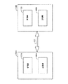
図1は例示的な通信システム100を図示している図である。図1を参照すると、例示的な通信システムは2つのトランシーバ104aおよび104bを備えている。トランシーバ104aおよび104bは、それぞれ送信機108aおよび108b、受信機112aおよび112bを持っている。
【0023】
データまたは他の情報は送信機108(108a、108b)から、送信パス122を通して、信号が向けられている他のトランシーバ104(104a、104b)中の受信機112(112a、112b)に送られる。衛星、セルラおよび他の無線通信システムでは、送信パス122は空中である。しかしながら、本発明はこのような適用に限定されるものではなく、送信パス122は技術的に知られている有線あるいは他の信号伝送媒体とすることができる。
【0024】
ある環境では、送信パス122は、データがデータパケットで送信されるパケット化データパスである。これは通常、情報がデジタルデータの形態であるケースである。他の環境では、アナログデータが搬送波に変調され、送信パス122を通して送信される。
【0025】
セルラ通信システムの例では、1つのトランシーバ104(104a、104b)をハンドヘルド型あるいは移動体セルラ電話機に配置することができ、あるいは配置し、無線デバイスまたは電話機の現在の領域すなわち物理的な位置でサービスを提供しているローカルセルサイトの基地局に他のトランシーバ104(104b、104a)を配置する。衛星通信システムの例では、1つのトランシーバ104(104a、104b)はハンドヘルド型、移動体、あるいは固定トランシーバ(すなわち衛星電話機)とすることができ、他のトランシーバ104(104b、104a)はゲートウェイ(すなわち地球局ゲートウェイ)に配置する。衛星通信システムの例では、技術的によく知られているように、(図示されていない)衛星が使用されてトランシーバ104(104b、104a)間で信号が中継される。代わりに、衛星通信システムの例では、1つのトランシーバ104を衛星自体に搭載して配置することができる。
【0026】
本発明はこの例示的な環境に関して説明する。これらの用語での説明は便宜のためだけに提供されるものである。本発明をこの例示的な環境における適用に制限するように意図するものではない。実際、以下の説明を読むと、無線デバイスの電力が遠隔的に制御されるあるいは遠隔的に制御できる代替環境において本発明をどのように実現すればよいか関連技術の当業者に明らかになるであろう。
【0027】
III.電力制御
通信システムでは、“電力制御モード”として呼ばれる電力制御方式を使用して電力を制御することができる。この説明のために、少なくとも“追跡モード”と“バーストモード”の2つの電力制御モードがある。電力制御の追跡モードとバーストモードの両者は、システム性能が許容可能なレベルより下に落ちたときに電力の増加をもたらす。しかしながらバーストモードでは、追跡モードで提供されるものよりも電力増加量が多い。
【0028】
追跡モードとバーストモードとの間の選択は通信リンクのシステム性能に基づいてなされる。特に、システム性能が予め選択された公称範囲内である場合には追跡モードが利用される。しかしながら、システム性能がこの公称範囲より下に落ちた場合には、バーストモードの電力制御が利用される。バーストモードの利用により、追跡モードに対するケースよりもより速くシステム性能が公称範囲になる。
【0029】
したがって追跡モードは、SNRがしきい値レベルに対して少しだけ上下して変化する公称動作状態で電力を制御するのによく適合する。これに対してバーストモードは、大きな電力低下を受ける状態で電力を制御するのによく適合する。このような状態は、例えば通信パスが大きなビルあるいは他の干渉構造物または条件によりブロックされる場合から生じる。
【0030】
1つの実施形態では、システム性能は、(送信機108aまたは108bのような)送信機により送信される信号の信号対雑音比(SNR)に基づく。この実施形態では、追跡モードは、信号対雑音比(SNR)が許容可能なレベルより下に落ちたときにわずかな増分だけ電力を増加させる。バーストモードも、信号対雑音比(SNR)が許容可能なレベルより下に落ちたときに電力を増加させる。しかしながらバーストモードでは、電力増加量は追跡モードでもたらされるものよりも多い。2つのモード間の選択は、どれぐらいSNRが許容可能なレベルよりも下に落ちるかに基づいてなされる。すなわち、通信リンクの性能が公称であると考えられるか否かに基づく。他の実施形態では、システム性能はSNRとは独立した受信信号強度に基づく。
【0031】
代替実施形態では、システム性能はエラーで受信されたフレーム数に基づく。この実施形態では、受信機が所定の時間期間に多量のエラーフレーム(あるいは特定数の連続したエラーフレーム)を受信した場合に、電力制御のためにバーストモードが選択される。一方、受信機がたまにフレームエラーを受信するだけである場合には、追跡モードが選択される。
【0032】
1つの実施形態では、各モードに対する電力増加はインクリメント的である。すなわち、電力を増加させるための所定のコマンドまたは決定に対して、電力は予め選択されたインクリメント量だけ増加される。再度電力を増加させる後続するコマンドまたは決定がなされるまで電力は再度増加されない。代替実施形態では、電力を増加させるための所定のコマンドまたは決定に対して、電力増加を終了するために後続するコマンドが受信されるまで電力は徐々に増加される。いずれの実施形態においても、バーストモードは追跡モードよりもより大きな電力増加をもたらす。すなわち、バーストモードは第1の実施形態ではより大きなインクリメント量の電力増加をもたらし、第2の実施形態ではより速いレートの増加をもたらす。
【0033】
図2は追跡モードのみで電力が制御される例示的な動作シナリオを図示している図である。図2では、水平軸は時間を表しており、垂直軸はSNRを表している。しきい値SNRは水平線204により図示されている。送信信号の実際のSNRの例は、時間的に変化する線208により図示されている。図2に図示されている例では、デバイスは時間T1まで公称的に動作している。この領域では、送信機108のSNR208はSNRしきい値204に関してわずかな量だけ変化する。わずかなインクリメント量で送信電力に対して調整がなされる。SNR208がしきい値204より下に落ちたときには、電力はインクリメント的に増加される。逆に、SNF208がしきい値204より上に上昇したときには、電力はインクリメント的に減少される。電力調整は技術的にコマンドまたは制御および操作技術を使用して行われる。
【0034】
時間T1において、送信パス122を伝搬する信号のSNRが大きく低下する。これは例えばパスが妨害された場合に起こり得る。追跡モードでは、電力はインクリメント的に増加されてSNRを改善させる。しかしながら、追跡モードでは電力はインクリメントごとにわずかに増加するだけであることから、SNRが再び許容可能なレベルに到達する前にかなりの時間が経過する。これは時間帯ttにより図示されている。
【0035】
図3は、追跡モードおよびバーストモードの両者で電力が選択的に制御される例示的な動作シナリオを示している図である。図2と同様に、図3では、水平軸は時間を表し、垂直軸はSNRを表している。しきい値SNRは水平線204により図示されている。送信信号の実際のSNRの例は時間的に変化する線208により図示されている。図3に図示されている例では、デバイスは時間T1まで公称的に動作している。この領域では、送信機108の送信信号のSNR208はSNRしきい置204に関してわずかな量だけ変化する。この時間の間では、送信機108は追跡モードで動作し、わずかなインクリメント量で送信電力に対して調整がなされる。SNR208がしきい値204より下に落ちたときには、電力はインクリメント的に増加される。
【0036】
時間T1において、送信パス122が妨害され、SNRが大きく低下したときには、送信機電力制御モードはバーストモードにスイッチングされる。先に説明したように、バーストモードでは電力増加は追跡モードよりさらに顕著である。このように、SNRが許容可能なレベルに戻るまでにかかる時間量tbは追跡モードで要求される時間ttよりもかなり短い。時間T2においてSNR208がしきい値204に到達したときには、送信機108は追跡モードにスイッチングされる。
【0037】
公称動作状態中にバーストモードのままに維持することは一般的に好ましくないことに留意すべきである。これは、SNRのわずかな減少がバーストモードでは送信電力の大きな増加となるからである。これは送信電力が過剰となるためにしきい値204より十分上にSNR208を増加させ、過度の電力量を消費させる。これは電力を無駄にし、電力が制限されたシステムでは、電力は容量に影響を与え、これは非常に好ましくないことが分かる。システムが補償を行ってしきい値レベルに戻そうと試み、各方向にオーバーシュートするときには、状況によってはこれは振動的動作も生じさせるかもしれない。
【0038】
1つの実施形態では、電力制御モードの選択は受信機112によりなされる。この実施形態では、受信機112(112a、112b)は(対向するトランシーバ104の)送信機108(108b、108a)に命令して、必要なときに電力制御モードをスイッチングさせる。これは例えば送信信号のコマンド部分で行うことができる。代替実施形態では、受信機112は情報を送信機104に戻して、電力制御モードをスイッチングさせるか否かの決定を送信機104が行えるようにする。例えば、この代替実施形態では、受信機112はフレームエラー表示、ビットエラーレート値、SNR値、またはシステムの性能が許容可能なレベルにあるか否かを示す他の何らかの表示のような1つ以上の表示を送信してもよい。
【0039】
図4は本発明の1つの実施形態にしたがって適切な電力制御モードを決定して選択するプロセスを一般的に示している動作フロー図である。ステップ304において、受信機112(112a、11b)は送信機108(108b、108a)により送信される信号を受信する。先に説明した例示的な環境では、信号は送信パス122を通して送信される。
【0040】
受信機112(112a、112b)は受信信号のSNR208が予め選択されたしきい値204より上か、予め選択されたしきい値204か、あるいは予め選択されたしきい値204より下にあるかを決定する。これは通信システムが動作している電力制御モードに関係なく行うことができる。この決定は決定ステップ308により図示されている。受信信号のSNR208がしきい値204より上である場合には、電力は下向きに調整され、動作はステップ304に戻り、ここで受信機108は送信された信号を受信し続ける。これはステップ310とフロー線362により図示されている。
【0041】
SNR208がしきい値204にあり、したがって調整の必要がない場合には、フロー線364により図示されているように動作はステップ304に戻る。1つの実施形態では、しきい値204は単一の値として実現されず、その代わりにSNR値の許容可能な範囲を含む。
【0042】
一方、SNR208がしきい値より下の場合には、本発明の動作はステップ312に進む。ステップ312では、受信機112はSNR208の低下が公称よりも大きいか否かを決定する。言い換えると、受信機112はSNR208がしきい値204より下の許容可能な量よりも大きいか否かを決定し、したがってSNR208をしきい値204に戻すのに望まれるものよりも長くかかることから追跡モードは好ましくないか否かを決定する。
【0043】
SNR208の低下が公称制限内である場合には、ブロック316により図示されているように、電力制御モードは追跡モードとして選択される。電力制御モードが既に追跡モードである場合には、送信機108は追跡モードのままである。しかしながら、現在の電力制御モードがバーストモードである場合には、ブロック316はバーストモードから追跡モードへの変化を表す。ステップ320では、送信機の電力は追跡モードで調整される。受信機112はフロー線366、364により図示されているように送信を受信し続ける。
【0044】
SNR208の低下が公称制限を越えた場合には、選択される電力制御モードは、ステップまたはブロック326により図示されているようにバーストモードである。電力制御モードが既にバーストモードである場合には、送信機108はバーストモードのままである。しかしながら、現在の電力制御モードが追跡モードである場合には、ステップ326は追跡モードからバーストモードへの変化を表す。ステップ330では、電力はバーストモードで調整される。受信機112はフロー線368により図示されているように送信を受信し続ける。
【0045】
しきい値およびしきい値より下の値は特定の適用に適合するように選択することができる。1つの実施形態では、しきい値204は単一の値ではなく、値の範囲であり、したがって受信信号がその範囲内にある限り、信号はしきい値にあると言われる。
【0046】
1つの実施形態では、ステップ308および312でなされる決定は本質的にSNRに基づいておらず、その代わりに、エラーで受信されたフレーム数に基づく。例えば、この実施形態の1つのモードでは、受信機112は過去X個のフレームのうちいくつのフレームがエラーで受信されたかを決定する。この例では、過去XフレームのうちY個より多いものがエラーで受信された場合に、これは許容可能な範囲を越えるエラーレートを表し、好ましい電力制御モードはバーストモードである。
【0047】
この実施形態の他のモードでは、受信機112はいくつの連続フレームがエラーで受信されたかを決定する。エラーで受信された連続フレームの数が予め定められた制限となるか、あるいはこれを越えた場合には、これは許容可能な範囲を越えるエラーレートを表し、好ましい電力制御モードはバーストモードである。エラーで受信されたフレーム数を決定することは、例えば巡回冗長検査(CRC)コードによるような既知の技術を使用して達成することができる。
【0048】
さらに別の実施形態では、本発明は受信信号のビットエラーレート(BER)を見る。しきい値より上に上昇するBERはしきい値204より下に落ちるSNR208に類似している。BERが予め定められた量よりも多くしきい値より上に上昇した場合には、システムはもはや公称的に動作しておらず、好ましい追跡モードはバーストモードである。
【0049】
本発明とともに他のパラメータをどのように利用するとシステムが公称的に動作しているか否かを決定できるかは関連技術の当業者に明らかになるであろう。
【0050】
先に説明した実施形態では、受信機112はシステムがしきい値にあるか、しきい値より上にあるか、あるいはしきい値より下にあるかを決定し、システムが公称的に動作しているか否かを決定するように説明されている。この実施形態では、受信機112(112a、112b)は、適切なときに送信機108にモードを変更するように命令するコマンドを送信機108(108b、108a)に送信する。代替実施形態では、受信機112は単に遠隔測定データを送信機108に提供する。この遠隔測定データは、好ましい電力制御モードが追跡モードであるかあるいはバーストモードであるかを決定するのに十分な情報を送信機108に提供する。
【0051】
1つの構成では、受信機はメッセージまたはコマンドにおいてビットの形態で2つのフィードバック表示を提供する。1つのビットは“追跡モードのアップ/ダウンコマンド”を表示するために使用され、他のビットは“バーストモードの送信レベル調整”を示す。何が実行され、あるいは実現されるかを決定するのは送信機の役割である。これらに限定されないが、連続的なフレームエラー数などのような要因に基づいて送信機により決定がなされる。このアプローチでは、より速い反応時間がシステムに提供される。その理由は、電力制御目的のために消費される増加した帯域幅の犠牲により、エラーのような重要な事象が送信機に直ちに報告されるからである。
【0052】
受信機112が送信機108にコマンドを送信して電力制御モードをスイッチングさせる実施形態では、コマンドが送信中に失われる可能性がある。このシナリオはいくつかの異なる技術の任意のものを使用して取り扱うことができる。1つの技術は肯定応答メッセージを使用してコマンドの受信を確認する。
【0053】
第2の技術は、単にコマンドを送信し続けることである。例えば、システムが公称範囲外で動作している場合には、受信機112は、システムが公称動作に戻るまで各コマンドフレーム中にバーストモードで追跡するようにコマンドを送信する。コマンドが反復されることから、そしてこの反復は多くのケースでは不必要であることから、この技術は要求されるものよりも多くの帯域幅を消費する。この理由のために、この技術は好ましくないかもしれない。
【0054】
さらに別の技術にしたがうと、電力制御の変更またはコマンドの実施または非実施が単に無視される。すなわち、送信機108がコマンドで命令されたような電力制御モードに実際にスイッチングしたか否かを決定する検査がない。この実施形態は直感に反するように思えるかもしれないが、実際には好ましい実施形態である。なぜかを理解するために、モードをスイッチングするコマンドを受信機112により送信することができ、送信機108により受信されない2つの状況を考察する。第1の状況では、SNR208はかなり減少し、受信機112は送信機108にコマンドを送信して、電力制御モードをバーストモードにスイッチングさせる。送信機108がこのコマンドを受信しなかった場合には、唯一の否定的な結果は、送信機108が追跡モードで電力を制御し続けることである。すなわち、コマンドが送信機108により受信されたケースよりも公称動作に戻るのにより時間がかかる。
【0055】
第2の状況では、送信機108がバーストモードで動作し、信号が公称範囲に戻っている。追跡モードに変更するように命令するコマンドを送信機108が受信機112から受信しない場合には、電力は要求されるよりも大きく増加されるかもしれない。しかしながら、これはシステムが動作し続けるのに致命的なエラーではない。唯一の欠点は要求されるよりも多くの電力が消費されることである。
【0056】
先の説明を読むと、追跡モードおよびバーストモードの代わりに、あるいはこれらに追加して、代わりの電力制御モードを使用してどのように電力制御モード選択を実現するかは関連技術の当業者に明らかになるであろう。
【0057】
IV.しきい値最適化
先に説明したように、多くの制御方式は(例えばSNR、電力レベルなどのような)通信システムのパラメータと、そのパラメータに対するしきい値との比較に基づいている。しかしながら、通信システムがしきい値においてあるいはしきい値近くで動作することがあり、好ましくないレベルのエラーまたはドロップアウトを依然として受ける環境がある。このような環境では、確立されたしきい値レベルは許容可能な通信を達成するのには低すぎる。
【0058】
通信チャネルの許容可能性を判断するのに使用される1つの基準は信号の“品質”と呼ばれる。信号が高い品質のものである場合には、システムはシステム性能の大きな減少を受けることなく所定のしきい値レベルであるいは所定のしきい値レベル近くで動作することができる。しかしながら、信号品質が低くなった場合には、同じしきい値レベルにおける動作または同じしきい値レベル近くの動作は許容できないレベルのシステム性能になることがある。言い換えると、より高い品質信号を持つ通信システムはより低いしきい値レベルで動作することができ、なおかつ所定レベルのシステム性能を維持することができる。
【0059】
信号の品質に影響を与えるかもしれない1つのシナリオは、例えば、ポータブルまたは移動体通信デバイスが信号に対する障害物がある領域で動作しているときに生じる。例えば、ポータブル通信デバイスを持って田舎の農業領域から大都市に移動しているユーザを考える。ユーザが田舎領域にいる間は、あったとしても障害物は少ない。この設定では、信号の品質は高く、所定のしきい値での動作は許容可能である。
【0060】
ユーザが大都市に入ったとき、いくつかの高いビルが通信パスを妨害する。これらの障害物の結果として、ポータブル通信デバイスから受信機に到達する信号は低下した品質のものとなる。結果として、デバイスがしきい値で動作し、システムの性能が低下した場合でさえ、エラー数の増加が生じ易い。この減少した品質を補償するために、動作がしきい値より上となるように、ポータブル通信デバイスの送信機の電力を増加させることが望ましい。しかしながら、ポータブル通信デバイスが従来の電力制御方式で動作している場合には、電力はしきい値より上に増加されない。したがって、本発明はしきい値レベルを増加させ、これは送信機の電力を増加させる電力制御モードとなる。
【0061】
本発明はシステムのしきい値レベルを増加させるので、電力制御モードは送信機の電力を増加させる。本発明にしたがうと、電力制御モードは信号レベル、ここではSNRをしきい値レベルにあるいはしきい値レベル近くに維持するように動作する。さらに本発明は(例えばエラーレートのような)システム性能を監視して、しきい値レベルを維持および更新し、これにより許容可能なレベルの性能を維持する。
【0062】
動作において、本発明はしきい値レベルを修正する必要があるか否かを決定する。1つの実施形態にしたがうと、この決定は、信号レベルとしきい値との差の量と、例えばシステムのエラーレートのようなシステム性能の予め定められた測定基準の2つの要因に基づいてなされる。信号レベルがしきい値にあるいはしきい値の近くにあり、システム性能が許容できない(例えば過剰な数のエラーが受信される)場合には、これはしきい値を増加させる必要があることの指標となる。同様に、信号がしきい値にあるいはしきい値の近くにあり、システム性能が予測したものよりもかなり良い(例えばエラーレートが確立された許容可能レベルよりもかなり低い)場合には、しきい値を低くして、これにより送信電力を節約して使用することができる。
【0063】
1つの実施形態では、信号レベル測定値がSNRしきい値204とSNR208の比較であり、システム性能を決定するのに使用される測定基準が受信信号のエラー数に基づくか、あるいは最後のNフレームに対してエラーで受信されたフレームの数に基づいていることが好ましい。この説明を読むと、本発明は信号強度に対する異なるパラメータでおよび/またはシステム性能を決定する異なる測定基準で実現できることが関連技術の当業者に明らかになるであろう。例えば、信号レベルは雑音レベルあるいは他の何らかの動作パラメータに関係のない信号強度とすることができる。さらに、システム性能測定基準として使用されるエラーの決定は、受信信号のエラー数、フレームエラーレート、連続フレームエラーの数、ビットエラーレート、あるいは他の要因に基づくことができる。
【0064】
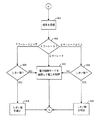
図5は本発明の1つの実施形態にしたがって本発明がしきい値レベルを増加させるか否かを決定するプロセスを図示している図である。図5を参照すると、ステップ404において、受信機112は送信機108から信号を受信して、信号パラメータを評価する。先に説明したように、好ましい実施形態では、これらのパラメータはSNR208と、最後のNフレームで受信されたフレームエラーの数である。先に説明したように他のパラメータを利用することができるが、説明を簡単にするために、これらのパラメータに関してプロセスを説明する。
【0065】
ステップ408において、システムは最後のNフレームで生じたフレームエラーの数を調べて、フレームエラーの数が許容可能であるか否かを決定する。最後のNフレームで生じたフレームエラーの数が確立された数より上であった場合には、これはシステム性能が確立されたレベルの許容性より下であることを示している。1つの実施形態ではN=300であるが、Nは任意の数を選択することができる。
【0066】
最後のNフレームで生じたフレームエラーの数が予測されたレベル(あるいは許容可能な範囲内)である場合には、システムは電力を制御するのに電力制御モードを使用し、正常として動作し続ける。これはステップ412により図示されている。
【0067】
最後のNフレーム中で生じたフレームエラーの数が確立された数(または範囲)より上である場合には、動作はステップ416に続き、ここで本発明はSNR208が公称であるか否かを決定する。すなわち、SNR208がしきい値204に十分近いか否かを決定する。1つの実施形態では、この決定は測定された受信信号SNR208としきい値204との積分された差を測定することによりなされる。
【0068】
SNR208がしきい値204にあるいはしきい値204の近くにあり、(ステップ408において先に決定されたように)エラーレートが許容できない場合には、これはしきい値204を増加させる必要があることを示す。これはステップ420で生じる。
【0069】
しかしながら、SNR208がしきい値204より下にあり、(ステップ408において先に決定されたように)エラーレートが許容できない場合には、これは電力制御モードが正常に動作していることを示す。しきい値204より下にあるSNR208の状態が(先のステップ408で決定された)許容できないくらい高いエラーレートになり易いことから、しきい値204は増加されない。このように、システムはステップ412で電力を制御するのに電力制御モードを使用して正常として動作し続ける。
【0070】
ステップ408に戻ると、ステップ408において最後のNフレーム中で生じたフレームエラーの数が予測数(あるいは範囲)より下であると決定された場合には、これはしきい値204が高すぎるかもしれない指標となる。したがって、ステップ424において、システムはSNR208がしきい値204にあるかあるいはしきい値204の近くにあるか否かを決定する。1つの実施形態では、この決定は測定された受信信号SNR208としきい値204との積分された差を測定することによりなされる。
【0071】
SNR208がしきい値より上である場合には、電力制御モードは電力を低くして、システムを適切に維持する。しかしながら、SNR208がしきい値にあるかしきい値近くにあり、エラーレートが予測よりも良い場合には、これはしきい値204を低くすることができることを示す。これはステップ428において生じる。
【0072】
図6は本発明の代替実施形態にしたがって本発明がしきい値レベルを増加させるか否かを決定するプロセスを図示している図である。図6を参照すると、ステップ504において、受信機112は送信機108から信号を受信して、信号パラメータを評価する。先に説明したように、好ましい実施形態では、これらのパラメータはSNR208と、最後のNフレームで受信されたフレームエラーの数である。先に説明したように他のパラメータに置換することができるが、説明を簡単にするためにこれらのパラメータに関してプロセスを説明する。
【0073】
ステップ508では、本発明はシステムがしきい値204であるいはしきい値204の十分近くで動作しているか否かを決定する。この発明は次にエラーの数が許容可能であるか、正常より上か、あるいは正常より下かを決定する。
【0074】
エラーレートが正常より上であり、システムがしきい値204であるいはしきい値204の近くで動作している場合には、ステップ508、524および520により図示されているように、しきい値204が増加される。
【0075】
エラーレートが正常より下であり、システムがしきい値であるいはしきい値近くで動作している場合には、ステップ508、524および516により図示されているように、しきい値204は低下される。
【0076】
エラーレートが正常であり、システムがしきい値に対して公称的に動作している場合には、しきい値204を調整する必要はなく、システムは必要とされるように電力制御モードで電力を調整し続ける。これはステップ508、524および532により図示されている。
【0077】
エラーレートが正常より上であり、システムがしきい値204より上で動作している場合には、しきい値204は増加される。これはステップ508、528および520により図示されている。
【0078】
エラーレートが正常より下であり、システムがしきい値より上で動作している場合には、しきい値204は調整されず、電力は電力制御モードにしたがって減少される。これはステップ508、528および532により図示されている。
【0079】
エラーレートが正常より下であり、システムがしきい値204より下で動作している場合には、ステップ508、512および516により図示されているようにしきい値204は低下される。
【0080】
エラーレートが正常より上であり、システムがしきい値204より下で動作している場合には、しきい値204は調整されず、電力は電力制御モードにしたがって増加される。これはステップ508、512および532により図示されている。
【0081】
V.結論
先の好ましい実施態様の説明は、当業者が本発明を利用できるよう提供されている。本発明はその好ましい実施形態を参照して特に図示し説明したが、本発明の精神および範囲を逸脱することなくさまざまな形態および詳細の変更をなし得ることは当業者に理解されるであろう。
【図面の簡単な説明】
【図1】 図1は、例示的な通信システムを図示しているブロック図である。
【図2】 図2は、電力制御モード間をスイッチングする例示的なプロセスを図示している図である。
【図3】 図3は、電力制御モード間をスイッチングする例示的なプロセスを図示している図である。
【図4】 図4は、適切な電力制御モードを決定および選択する例示的なプロセスを一般的に図示している動作フロー図である。
【図5】 図5は、本発明の1つの実施形態にしたがって本発明がしきい値レベルを増加させるかあるいはさせないかを決定するプロセスを図示している動作フロー図である。
【図6】 図6は、本発明の代替実施形態にしたがって本発明がしきい値レベルを増加させるかあるいはさせないかを決定するプロセスを図示している動作フロー図である。[0001]
BACKGROUND OF THE INVENTION
The present invention generally relates to wireless communication systems. In particular, the present invention relates to a new and improved apparatus and method for power control for wireless communication devices.
[0002]
[Prior art]
Wireless communication networks have gained considerable popularity in all aspects of business, industry and personal life. As such, portable handheld wireless communication devices have grown extensively in recent years. Portable devices such as cellular and personal communication service (PCS) telephones are now as common for business and personal users. In addition, modern systems such as satellite communication systems using portable handheld and mobile telephones are currently being designed.
[0003]
One design goal of handheld communication devices is low power consumption. Low power consumption extends battery life and generates less heat, which increases the usefulness of the device. In addition, low power consumption makes it possible to reduce the size of the device, or more often leads to a smaller device size.
[0004]
In a CDMA communication system, the signal transmission power in the system is controlled so that the amount of power required for any given communication link is maintained at a minimum level. This helps to maximize overall communication system capacity and maintain acceptable mutual interference and signal quality levels. By controlling the transmitted signal power at or near the minimum level, interference with other communication devices or units is reduced. An example of a power control technique in such a communication system is disclosed in US Pat. No. 5,383,219, 1995, entitled “Fast Forward Link Power Control in Code Division Multiple Access Systems”, issued January 17, 1995. US Pat. No. 5,396,516 entitled “Transmission Power Control System Method and System for Dynamic Correction of Transmission Parameters” issued March 7, 1993, “Transmission” issued November 30, 1993 No. 5,267,262, entitled “Power Control System”, which is incorporated herein by reference.
[0005]
One technique for reducing the amount of power consumed by a device is to minimize the amount of power in the transmitted signal. This is often accomplished by reducing the amount of power in the transmitted signal as much as possible without adversely affecting communication. One way in which this is achieved is to reduce as much power as possible so that the signal to noise ratio (SNR) does not fall below an acceptable level. If the SNR falls below an acceptable level, power is increased to return the SNR to an acceptable level.
[0006]
This approach is useful. The reason is that a minimum amount of power can be used for communication under optimum conditions. When operating under conditions that are less than optimal or ideal, i.e., within a building, in bad weather, or the like, to maintain acceptable communications (eg, maintain acceptable SNR) ) Transmit power is increased.
[0007]
A wireless communication device or cellular telephone is remotely controlled by some communication system, such as a cellular communication system or other wireless communication system. That is, a portion of the communication bandwidth between the device and the base station transceiver is dedicated to sending commands and status information. This command and status portion of the bandwidth is used to adjust the power of the signal transmitted by the device. If the SNR of the signal received by the base station falls below an acceptable level, the base station sends a command to the wireless device to increase its transmit power. Similarly, if the SNR of the received signal is within a sufficiently acceptable limit, the base station sends a command to the device to reduce the transmission power.
[0008]
However, most conventional systems are limited in how they control transmission power for wireless communication devices.
[0009]
Essential What is needed is an apparatus and method for optimizing power control in a wireless communication system.
[0010]
Book The invention is a new and improved apparatus and method for optimizing the setting of threshold levels used to control the power of a transmitter in a communication system. In accordance with the present invention, two parameters are used to determine whether the threshold level needs to be adjusted. These parameters are the system behavior compared to established thresholds and system performance.
[0011]
In accordance with the present invention, if system performance is degraded and the system is operating at a threshold, this is an indicator that the threshold needs to be increased. Thus, the present invention increases the threshold value. Accordingly, the power control portion of the communication system senses that the system is operating below a threshold (ie, a newly increased threshold) and increases the power of the system according to the power control mode. As a result, system performance is improved. If the performance is still degraded and the system is operating again at the new threshold, the threshold is further increased. This process continues until system performance returns to an acceptable level again.
[0012]
If system performance degrades and the system is operating below the threshold, this does not require adjustment of the threshold, increasing the transmitter power to bring the system to the threshold It should be noted that this is a necessary indicator. In one embodiment, this is achieved by increasing the power of the transmitter according to the power control mode of the communication system.
[0013]
If system performance is better than what is required, this is an indication that the transmitter power may be greater than what is required. If the system performance is better than required, the present invention determines whether the system is operating above a threshold. If so, the transmitter power is reduced according to the power control mode of the communication system. However, if the performance is better than what is required and the system is operating at or below the threshold, this is an indication that the threshold can be lowered. Thus, the present invention lowers the threshold value. Thus, the power control portion of the communication system senses that the system is operating above the threshold and reduces the system power according to the power control mode. As a result, transmitter power consumption is reduced. If the performance is even better than what is required and the system is still operating at or below the new threshold, the threshold is further reduced. This process continues until the system performance returns to normal again.
[0014]
If system performance exceeds demand and the system is operating above the threshold, this should lower the transmit power, and the threshold is an indicator that may not require adjustment. It should be noted that
[0015]
In one embodiment, the threshold determination is based on the signal-to-noise ratio (SNR) of the received signal at the receiver. The required SNR level is established as a threshold level. The actual SNR of the received signal is compared with the threshold SNR to determine system behavior with respect to the threshold.
[0016]
In one embodiment, system performance is determined based on the system error rate. In alternative embodiments, other metrics such as frame error, bit error rate, and some other indicator of system performance are used to determine system performance.
[0017]
An advantage of the present invention is that power consumption is reduced as a result of dynamic adjustment of the threshold. By lowering the threshold when signal quality is high, the system can reduce transmit power, thereby reducing power consumption. By increasing the threshold when the signal quality is degraded, the system can maintain an acceptable level of performance.
[0018]
The features, objects and advantages of the present invention will become more apparent from the detailed description set forth below when taken in conjunction with the drawings.
[0019]
The present invention has been described with reference to the accompanying drawings. In the figures, like reference numbers indicate identical or functionally similar components. The leftmost digit of the reference number identifies the drawing in which the reference number first appears.
[0020]
DETAILED DESCRIPTION OF THE INVENTION
I. Summary and discussion of the present invention
The present invention is a system for optimally determining a threshold level used to adjust signal power transmitted in a communication system or in a device operating in the communication system according to one or more power control modes. Alternatively directed to an apparatus and method. A method for achieving this is described below.
[0021]
II. Example environment
Before describing the present invention in detail, it is useful to describe an exemplary environment in which the present invention can be implemented. In a broad sense, the present invention can be implemented in any wired or wireless communication system, particularly where it is preferable to control the amount of power provided by the transmitter. Such environments include, but are not limited to, cellular communication systems, personal communication systems, satellite communication systems, and many other known communication systems.
[0022]
FIG. 1 is a diagram illustrating an exemplary communication system 100. Referring to FIG. 1, the exemplary communication system includes two transceivers 104a and 104b. Transceivers 104a and 104b have transmitters 108a and 108b and receivers 112a and 112b, respectively.
[0023]
Data or other information is sent from the transmitter 108 (108a, 108b) through the
[0024]
In some environments, the
[0025]
In the example of a cellular communication system, one transceiver 104 (104a, 104b) can be or can be located in a handheld or mobile cellular telephone and serviced in the current area or physical location of the wireless device or telephone. The other transceiver 104 (104b, 104a) is arranged at the base station of the local cell site providing In the example of a satellite communication system, one transceiver 104 (104a, 104b) can be a handheld, mobile, or fixed transceiver (ie, satellite phone) and the other transceiver 104 (104b, 104a) can be a gateway (ie, (Earth station gateway) In a satellite communication system example, a satellite (not shown) is used to relay signals between transceivers 104 (104b, 104a), as is well known in the art. Alternatively, in the example of a satellite communication system, one transceiver 104 can be installed on the satellite itself.
[0026]
The present invention will be described with respect to this exemplary environment. Explanations in these terms are provided for convenience only. It is not intended that the present invention be limited to application in this exemplary environment. Indeed, reading the following description will make it clear to those skilled in the relevant art how to implement the present invention in an alternative environment where the power of the wireless device is remotely controlled or remotely controlled. I will.
[0027]
III. Power control
In a communication system, power can be controlled using a power control scheme called “power control mode”. For this description, there are at least two power control modes, “tracking mode” and “burst mode”. Both power control tracking mode and burst mode result in an increase in power when the system performance falls below an acceptable level. However, the burst mode has more power increase than that provided in the tracking mode.
[0028]
The choice between tracking mode and burst mode is made based on the system performance of the communication link. In particular, the tracking mode is utilized when the system performance is within a preselected nominal range. However, when system performance falls below this nominal range, burst mode power control is utilized. The use of burst mode brings the system performance to the nominal range faster than the case for tracking mode.
[0029]
The tracking mode is therefore well suited for controlling power in nominal operating conditions where the SNR varies slightly up or down relative to the threshold level. In contrast, the burst mode is well suited for controlling power in the presence of a large power drop. Such a situation arises, for example, when a communication path is blocked by a large building or other interference structure or condition.
[0030]
In one embodiment, system performance is based on the signal to noise ratio (SNR) of a signal transmitted by a transmitter (such as transmitter 108a or 108b). In this embodiment, the tracking mode increases power by a small increment when the signal-to-noise ratio (SNR) falls below an acceptable level. Burst mode also increases power when the signal to noise ratio (SNR) falls below an acceptable level. However, in burst mode, the amount of power increase is greater than that provided in tracking mode. The choice between the two modes is made based on how much the SNR falls below an acceptable level. That is, based on whether the performance of the communication link is considered nominal. In other embodiments, system performance is based on received signal strength independent of SNR.
[0031]
In an alternative embodiment, system performance is based on the number of frames received in error. In this embodiment, the burst mode is selected for power control when the receiver receives a large number of error frames (or a specific number of consecutive error frames) in a predetermined time period. On the other hand, the tracking mode is selected if the receiver only occasionally receives frame errors.
[0032]
In one embodiment, the power increase for each mode is incremental. That is, for a predetermined command or decision to increase power, the power is increased by a preselected increment. The power is not increased again until a subsequent command or decision is made to increase the power again. In an alternative embodiment, for a given command or decision to increase power, the power is gradually increased until a subsequent command is received to end the power increase. In either embodiment, the burst mode provides a greater power increase than the tracking mode. That is, the burst mode provides a larger increment of power increase in the first embodiment and a faster rate increase in the second embodiment.
[0033]
FIG. 2 is a diagram illustrating an exemplary operating scenario in which power is controlled only in tracking mode. In FIG. 2, the horizontal axis represents time and the vertical axis represents SNR. The threshold SNR is illustrated by the
[0034]
Time T 1 , The SNR of the signal propagating through the
[0035]
FIG. 3 is a diagram illustrating an exemplary operating scenario in which power is selectively controlled in both tracking and burst modes. Similar to FIG. 2, in FIG. 3, the horizontal axis represents time and the vertical axis represents SNR. The threshold SNR is illustrated by the
[0036]
Time T 1 When the
[0037]
It should be noted that it is generally undesirable to remain in burst mode during nominal operating conditions. This is because a slight decrease in SNR results in a large increase in transmission power in burst mode. This increases the
[0038]
In one embodiment, the power control mode selection is made by the receiver 112. In this embodiment, the receiver 112 (112a, 112b) commands the transmitter 108 (108b, 108a) (of the opposing transceiver 104) to switch the power control mode when necessary. This can be done, for example, in the command portion of the transmission signal. In an alternative embodiment, the receiver 112 returns information to the transmitter 104 so that the transmitter 104 can determine whether to switch the power control mode. For example, in this alternative embodiment, receiver 112 may have one or more such as a frame error indication, a bit error rate value, an SNR value, or some other indication that indicates whether the system performance is at an acceptable level. May be sent.
[0039]
FIG. 4 is an operational flow diagram generally illustrating a process for determining and selecting an appropriate power control mode in accordance with one embodiment of the present invention. In
[0040]
Does receiver 112 (112a, 112b) have received
[0041]
If
[0042]
On the other hand, if the
[0043]
If the
[0044]
If the drop in
[0045]
The threshold and values below the threshold can be selected to suit a particular application. In one embodiment,
[0046]
In one embodiment, the decisions made in
[0047]
In another mode of this embodiment, the receiver 112 determines how many consecutive frames have been received in error. If the number of consecutive frames received in error reaches or exceeds a predetermined limit, this represents an error rate that exceeds an acceptable range and the preferred power control mode is burst mode. . Determining the number of frames received in error can be accomplished using known techniques such as, for example, with a cyclic redundancy check (CRC) code.
[0048]
In yet another embodiment, the present invention looks at the bit error rate (BER) of the received signal. A BER that rises above a threshold is similar to an
[0049]
It will be apparent to those skilled in the relevant art how other parameters in conjunction with the present invention can be used to determine whether a system is nominally operating.
[0050]
In the previously described embodiment, the receiver 112 determines whether the system is at, above, or below the threshold, and the system operates nominally. It is explained to determine whether or not. In this embodiment, the receiver 112 (112a, 112b) sends a command to the transmitter 108 (108b, 108a) instructing the transmitter 108 to change mode when appropriate. In an alternative embodiment, receiver 112 simply provides telemetry data to transmitter 108. This telemetry data provides the transmitter 108 with enough information to determine whether the preferred power control mode is the tracking mode or the burst mode.
[0051]
In one configuration, the receiver provides two feedback indications in the form of bits in the message or command. One bit is used to indicate a “tracking mode up / down command” and the other bit indicates “transmission level adjustment in burst mode”. It is the role of the transmitter that determines what is implemented or realized. Without being limited thereto, the transmitter makes a decision based on factors such as the number of consecutive frame errors. This approach provides a faster reaction time to the system. The reason is that important events such as errors are immediately reported to the transmitter at the expense of increased bandwidth consumed for power control purposes.
[0052]
In embodiments where the receiver 112 sends a command to the transmitter 108 to switch the power control mode, the command may be lost during transmission. This scenario can be handled using any of several different technologies. One technique uses an acknowledgment message to confirm receipt of the command.
[0053]
The second technique is simply to continue sending commands. For example, if the system is operating outside of the nominal range, the receiver 112 sends commands to track in burst mode during each command frame until the system returns to nominal operation. Because the command is repeated and this repetition is unnecessary in many cases, this technique consumes more bandwidth than is required. For this reason, this technique may not be preferred.
[0054]
According to yet another technique, power control changes or command implementations or non-implementations are simply ignored. That is, there is no test to determine whether transmitter 108 has actually switched to the power control mode as commanded. While this embodiment may seem counterintuitive, it is actually a preferred embodiment. To understand why, consider two situations where a command to switch modes may be sent by the receiver 112 and not received by the transmitter 108. In the first situation, the
[0055]
In the second situation, transmitter 108 is operating in burst mode and the signal is back in the nominal range. If the transmitter 108 does not receive a command from the receiver 112 that instructs it to change to the tracking mode, the power may be increased more than required. However, this is not a fatal error for the system to keep running. The only drawback is that more power is consumed than required.
[0056]
After reading the previous description, it will be clear to those skilled in the relevant art how to implement power control mode selection using alternative power control modes instead of or in addition to tracking and burst modes. It will become clear.
[0057]
IV. Threshold optimization
As explained above, many control schemes are based on comparisons of communication system parameters (such as SNR, power level, etc.) and thresholds for the parameters. However, there are circumstances in which a communication system may operate at or near a threshold and still receive an undesired level of error or dropout. In such an environment, the established threshold level is too low to achieve acceptable communication.
[0058]
One criterion used to determine the acceptability of a communication channel is called the “quality” of the signal. If the signal is of high quality, the system can operate at or near the predetermined threshold level without a significant reduction in system performance. However, if the signal quality is low, operation at or near the same threshold level may result in an unacceptable level of system performance. In other words, a communication system with a higher quality signal can operate at a lower threshold level and still maintain a predetermined level of system performance.
[0059]
One scenario that may affect signal quality occurs, for example, when a portable or mobile communication device is operating in an area where there are obstacles to the signal. For example, consider a user who is moving from a rural agricultural area to a large city with a portable communication device. While the user is in the countryside, there are few obstacles, if any. In this setting, the signal quality is high and operation at a predetermined threshold is acceptable.
[0060]
When a user enters a big city, several tall buildings block the communication path. As a result of these obstacles, the signal arriving from the portable communication device to the receiver is of reduced quality. As a result, an increase in the number of errors is likely to occur even when the device operates at a threshold and system performance is degraded. In order to compensate for this reduced quality, it is desirable to increase the power of the portable communication device transmitter so that the operation is above the threshold. However, if the portable communication device is operating in a conventional power control scheme, power is not increased above the threshold. Thus, the present invention increases the threshold level, which is a power control mode that increases the power of the transmitter.
[0061]
Since the present invention increases the threshold level of the system, the power control mode increases the power of the transmitter. In accordance with the present invention, the power control mode operates to maintain the signal level, here the SNR, at or near the threshold level. In addition, the present invention monitors system performance (eg, error rate) to maintain and update threshold levels, thereby maintaining an acceptable level of performance.
[0062]
In operation, the present invention determines whether the threshold level needs to be modified. According to one embodiment, this determination is made based on two factors: the amount of difference between the signal level and the threshold and a predetermined metric of system performance, such as the system error rate. . If the signal level is at or near the threshold and the system performance is unacceptable (eg, an excessive number of errors are received), this may indicate that the threshold needs to be increased. It becomes an indicator. Similarly, if the signal is at or near the threshold and the system performance is much better than expected (eg, the error rate is much lower than the established acceptable level), the threshold is reached. The value can be lowered, thereby saving transmission power and using it.
[0063]
In one embodiment, the signal level measurement is a comparison of the
[0064]
FIG. 5 is a diagram illustrating a process for determining whether the present invention increases a threshold level according to one embodiment of the present invention. Referring to FIG. 5, in
[0065]
In
[0066]
If the number of frame errors that occurred in the last N frames is at the expected level (or within an acceptable range), the system uses the power control mode to control power and continues to operate normally. . This is illustrated by
[0067]
If the number of frame errors that occurred in the last N frames is above the established number (or range), operation continues to step 416 where the present invention determines whether
[0068]
If
[0069]
However, if
[0070]
Returning to step 408, if it is determined in
[0071]
If the
[0072]
FIG. 6 is a diagram illustrating a process for determining whether the present invention increases a threshold level according to an alternative embodiment of the present invention. Referring to FIG. 6, in
[0073]
In
[0074]
If the error rate is above normal and the system is operating at or near
[0075]
If the error rate is below normal and the system is operating at or near the threshold, the
[0076]
If the error rate is normal and the system is operating nominally with respect to the threshold, there is no need to adjust the
[0077]
If the error rate is above normal and the system is operating above
[0078]
If the error rate is below normal and the system is operating above the threshold, the
[0079]
If the error rate is below normal and the system is operating below
[0080]
If the error rate is above normal and the system is operating below
[0081]
V. Conclusion
The previous description of preferred embodiments is provided to enable any person skilled in the art to utilize the invention. Although the invention has been particularly shown and described with reference to preferred embodiments thereof, those skilled in the art will recognize that various changes in form and detail may be made without departing from the spirit and scope of the invention. .
[Brief description of the drawings]
FIG. 1 is a block diagram illustrating an exemplary communication system.
FIG. 2 is a diagram illustrating an exemplary process for switching between power control modes.
FIG. 3 is a diagram illustrating an exemplary process for switching between power control modes.
FIG. 4 is an operational flow diagram generally illustrating an exemplary process for determining and selecting an appropriate power control mode.
FIG. 5 is an operational flow diagram illustrating a process in which the present invention determines whether to increase or not increase a threshold level according to one embodiment of the present invention.
FIG. 6 is an operational flow diagram illustrating a process for determining whether the present invention increases or does not increase the threshold level according to an alternative embodiment of the present invention.
Claims (27)
予め定められた測定基準に基づいて通信システムの性能を決定するステップと、
通信のしきい値に関して、通信システム中の送信機の電力を決定するステップと、
通信システムの前記性能と前記しきい値に関する送信機の電力とに基づいて、しきい値を調整するステップとを含み、
前記予め定められた測定基準は、システムのエラーレート、フレームエラーレート、連続的なフレームエラーの数、およびビットエラーレートからなるグループから選択され、
前記通信システムの性能を決定するステップは、通信システムのパラメータが規定された範囲内にあるか否かを決定するステップをさらに含む方法。In a method for adjusting a threshold level in a communication system having at least one mode for controlling power of a transmitter in the communication system during system operation,
Determining the performance of the communication system based on predetermined metrics;
Respect of the communication threshold, determining a power of the transmitter in a communication system,
Based on the transmitter power for the performance and the threshold of the communication system, it viewed including the step of adjusting the threshold,
The predetermined metric is selected from the group consisting of system error rate, frame error rate, number of consecutive frame errors, and bit error rate;
Step further including a method for determining whether within the parameters of the communication system has been defined to determine the performance of the communication system.
前記調整するステップは、システムがしきい値でまたはしきい値近くで動作しているか否かを決定する前記ステップの結果に基づいてしきい値を調整することを含む請求項1記載の方法。Determining the power includes determining whether the system is operating at or near a threshold;
The method of claim 1 further comprising that the system adjusts the threshold based on the result of said step of determining whether operating near the threshold or thresholds for the adjustment.
前記システムがしきい値でまたはしきい値近くで動作し、システムの性能が許容可能なレベルより上および下のうちの1つであるとき、しきい値を調整するステップと、
さもなければ、しきい値を維持するステップとを含む請求項1記載の方法。Wherein the step of adjusting the
Adjusting the threshold when the system operates at or near the threshold and the system performance is one of above and below an acceptable level;
Otherwise, maintaining the threshold value.
前記システムがしきい値でまたはしきい値の近くで動作し、システムの性能が許容可能なレベルより上および下のうちの1つであるとき、
前記システムがしきい値より下で動作し、システムの性能が許容可能なレベルより上および許容可能なレベルのうちの1つであるとき、
前記システムがしきい値より上で動作し、システムの性能が許容可能なレベルより下および許容可能なレベルのうちの1つであるとき、
しきい値を調整するステップと、
さもなければ、しきい値を維持するステップとを含む請求項1記載の方法。Wherein the step of adjusting the
When the system operates at or near a threshold and the system performance is one of above and below an acceptable level;
When the system operates below a threshold and the system performance is one of above and below an acceptable level,
When the system operates above a threshold and the performance of the system is one of below and acceptable levels,
Adjusting the threshold;
Otherwise, maintaining the threshold value.
予め定められた測定基準に基づいて通信システムの性能を決定する手段と、
前記しきい値に関して、通信システム中の送信機の電力を決定する手段と、
通信システムの前記性能と前記しきい値に関する送信機の電力とに基づいて、しきい値を調整する手段とを具備し、
前記予め定められた測定基準は、システムのエラーレート、フレームエラーレート、連続的なフレームエラーの数、およびビットエラーレートからなるグループから選択され、
前記通信システムの性能を決定する手段は、通信システムのパラメータが規定された範囲内にあるか否かを決定する手段を備えている装置。 In an apparatus for adjusting a threshold level in a communication system having at least one mode for controlling power of a transmitter in the communication system during system operation,
Means for determining communication system performance based on predetermined metrics;
Means for determining the power of a transmitter in the communication system with respect to the threshold;
Means for adjusting the threshold based on the performance of the communication system and the transmitter power related to the threshold ;
The predetermined metric is selected from the group consisting of system error rate, frame error rate, number of consecutive frame errors, and bit error rate;
The apparatus for determining the performance of the communication system comprises means for determining whether or not parameters of the communication system are within a prescribed range.
前記システムがしきい値でまたはしきい値近くで動作し、システムの性能が許容可能なレベルより上および下のうちの1つであるとき、しきい値を調整し、
さもなければ、しきい値を維持するように適合されている請求項15記載の装置。Said means for adjustment,
Adjusting the threshold when the system operates at or near the threshold and the system performance is one of above and below an acceptable level;
The apparatus of claim 15 , wherein the apparatus is otherwise adapted to maintain a threshold.
前記システムがしきい値でまたはしきい値近くで動作し、システムの性能が許容可能なレベルより上および下のうちの1つであるとき、
前記システムがしきい値より下で動作し、システムの性能が許容可能なレベルより上および許容可能なレベルのうちの1つであるとき、
前記システムがしきい値より上で動作し、システムの性能が許容可能なレベルより下および許容可能なレベルのうちの1つであるとき、しきい値を調整し、
さもなければ、しきい値を維持するように適合されている請求項15記載の装置。Said means for adjustment,
When the system operates at or near a threshold and the performance of the system is one of above and below an acceptable level;
When the system operates below a threshold and the system performance is one of above and below an acceptable level,
Adjusting the threshold when the system operates above the threshold and the performance of the system is one of below and acceptable levels;
The apparatus of claim 15 , wherein the apparatus is otherwise adapted to maintain a threshold.
Applications Claiming Priority (7)
| Application Number | Priority Date | Filing Date | Title |
|---|---|---|---|
| US6281997P | 1997-10-13 | 1997-10-13 | |
| US6282197P | 1997-10-13 | 1997-10-13 | |
| US60/062,819 | 1997-10-13 | ||
| US60/062,821 | 1997-10-13 | ||
| US09/164,384 | 1998-09-30 | ||
| US09/164,384 US6259928B1 (en) | 1997-10-13 | 1998-09-30 | System and method for optimized power control |
| PCT/US1998/021253 WO1999019995A1 (en) | 1997-10-13 | 1998-10-05 | Apparatus and method for optimized power control |
Publications (3)
| Publication Number | Publication Date |
|---|---|
| JP2001520475A JP2001520475A (en) | 2001-10-30 |
| JP2001520475A5 JP2001520475A5 (en) | 2006-02-16 |
| JP4259753B2 true JP4259753B2 (en) | 2009-04-30 |
Family
ID=27370377
Family Applications (1)
| Application Number | Title | Priority Date | Filing Date |
|---|---|---|---|
| JP2000516443A Expired - Fee Related JP4259753B2 (en) | 1997-10-13 | 1998-10-05 | Apparatus and method for optimized power control |
Country Status (10)
| Country | Link |
|---|---|
| EP (1) | EP1048131B1 (en) |
| JP (1) | JP4259753B2 (en) |
| KR (1) | KR100709522B1 (en) |
| CN (1) | CN1146138C (en) |
| AT (1) | ATE300813T1 (en) |
| AU (1) | AU757622B2 (en) |
| CA (1) | CA2306920C (en) |
| DE (1) | DE69831014T2 (en) |
| HK (1) | HK1033050A1 (en) |
| WO (1) | WO1999019995A1 (en) |
Families Citing this family (34)
| Publication number | Priority date | Publication date | Assignee | Title |
|---|---|---|---|---|
| US6185432B1 (en) * | 1997-10-13 | 2001-02-06 | Qualcomm Incorporated | System and method for selecting power control modes |
| US7366133B1 (en) | 1999-12-30 | 2008-04-29 | Aperto Networks, Inc. | Integrated, self-optimizing, multi-parameter/multi-variable point-to-multipoint communication system [II] |
| US6654384B1 (en) | 1999-12-30 | 2003-11-25 | Aperto Networks, Inc. | Integrated self-optimizing multi-parameter and multi-variable point to multipoint communication system |
| KR100531361B1 (en) * | 2000-12-30 | 2005-11-28 | 엘지전자 주식회사 | Method for Controlling Power in Direct-Spreading CDMA |
| WO2002058278A1 (en) * | 2001-01-17 | 2002-07-25 | Fujitsu Limited | Outer loop power control device and method |
| JP4016647B2 (en) * | 2001-05-17 | 2007-12-05 | 日本電気株式会社 | Mobile communication system, base station, mobile station, threshold setting method used therefor, and program thereof |
| US8315226B2 (en) | 2006-01-05 | 2012-11-20 | Qualcomm Incorporated | Power control and handoff with power control commands and erasure indications |
| GB2447889B (en) * | 2007-03-21 | 2012-02-29 | Motorola Mobility Inc | Power control in a cellular communication system |
| US8027640B2 (en) * | 2008-12-17 | 2011-09-27 | Motorola Solutions, Inc. | Acoustic suppression using ancillary RF link |
| CN101827435A (en) * | 2010-03-17 | 2010-09-08 | 中兴通讯股份有限公司 | Energy saving method, access entity and user device for communication system device |
| US8935774B2 (en) | 2012-03-02 | 2015-01-13 | Microsoft Corporation | Accessory device authentication |
| US9426905B2 (en) | 2012-03-02 | 2016-08-23 | Microsoft Technology Licensing, Llc | Connection device for computing devices |
| US9134807B2 (en) | 2012-03-02 | 2015-09-15 | Microsoft Technology Licensing, Llc | Pressure sensitive key normalization |
| US9870066B2 (en) | 2012-03-02 | 2018-01-16 | Microsoft Technology Licensing, Llc | Method of manufacturing an input device |
| USRE48963E1 (en) | 2012-03-02 | 2022-03-08 | Microsoft Technology Licensing, Llc | Connection device for computing devices |
| US9360893B2 (en) | 2012-03-02 | 2016-06-07 | Microsoft Technology Licensing, Llc | Input device writing surface |
| US9075566B2 (en) | 2012-03-02 | 2015-07-07 | Microsoft Technoogy Licensing, LLC | Flexible hinge spine |
| US9064654B2 (en) | 2012-03-02 | 2015-06-23 | Microsoft Technology Licensing, Llc | Method of manufacturing an input device |
| US20130300590A1 (en) | 2012-05-14 | 2013-11-14 | Paul Henry Dietz | Audio Feedback |
| US10031556B2 (en) | 2012-06-08 | 2018-07-24 | Microsoft Technology Licensing, Llc | User experience adaptation |
| US9019615B2 (en) | 2012-06-12 | 2015-04-28 | Microsoft Technology Licensing, Llc | Wide field-of-view virtual image projector |
| US8964379B2 (en) | 2012-08-20 | 2015-02-24 | Microsoft Corporation | Switchable magnetic lock |
| US9317072B2 (en) | 2014-01-28 | 2016-04-19 | Microsoft Technology Licensing, Llc | Hinge mechanism with preset positions |
| US9447620B2 (en) | 2014-09-30 | 2016-09-20 | Microsoft Technology Licensing, Llc | Hinge mechanism with multiple preset positions |
| US9629004B2 (en) | 2014-10-17 | 2017-04-18 | Microsoft Technology Licensing, Llc | Indication of wireless signal quality using detected errors in data |
| CN104618039B (en) * | 2015-01-27 | 2017-10-10 | 南京航空航天大学 | A kind of algorithm and receiver for adjusting receiver performance in real time according to communication condition |
| US9752361B2 (en) | 2015-06-18 | 2017-09-05 | Microsoft Technology Licensing, Llc | Multistage hinge |
| US9864415B2 (en) | 2015-06-30 | 2018-01-09 | Microsoft Technology Licensing, Llc | Multistage friction hinge |
| US10344797B2 (en) | 2016-04-05 | 2019-07-09 | Microsoft Technology Licensing, Llc | Hinge with multiple preset positions |
| US10037057B2 (en) | 2016-09-22 | 2018-07-31 | Microsoft Technology Licensing, Llc | Friction hinge |
| US10129834B2 (en) * | 2017-03-31 | 2018-11-13 | Intel Corporation | Transmission power control methods and devices |
| CN112203295A (en) * | 2019-07-08 | 2021-01-08 | 索尼公司 | Electronic device, wireless communication method, and computer-readable medium |
| CN112399541B (en) * | 2019-08-16 | 2022-08-09 | 华为技术有限公司 | Uplink power control method and device suitable for non-ground network |
| CN113014413A (en) * | 2019-12-20 | 2021-06-22 | 中兴通讯股份有限公司 | Threshold optimization method, apparatus and computer readable medium applied to communication system |
Family Cites Families (5)
| Publication number | Priority date | Publication date | Assignee | Title |
|---|---|---|---|---|
| IE62238B1 (en) * | 1988-02-25 | 1995-01-11 | Dieter Stephan | Process and apparatus for producing blister packs |
| SE467332B (en) * | 1990-06-21 | 1992-06-29 | Ericsson Telefon Ab L M | PROCEDURE FOR POWER CONTROL IN A DIGITAL MOBILE PHONE SYSTEM |
| EP0548939B1 (en) * | 1991-12-26 | 2000-09-13 | Nec Corporation | Transmission power control system capable of keeping signal quality constant in mobile communication network |
| US5333175A (en) * | 1993-01-28 | 1994-07-26 | Bell Communications Research, Inc. | Method and apparatus for dynamic power control in TDMA portable radio systems |
| US5873028A (en) * | 1994-10-24 | 1999-02-16 | Ntt Mobile Communications Network Inc. | Transmission power control apparatus and method in a mobile communication system |
-
1998
- 1998-10-05 CA CA002306920A patent/CA2306920C/en not_active Expired - Fee Related
- 1998-10-05 AU AU96908/98A patent/AU757622B2/en not_active Ceased
- 1998-10-05 KR KR1020007003964A patent/KR100709522B1/en not_active IP Right Cessation
- 1998-10-05 DE DE69831014T patent/DE69831014T2/en not_active Expired - Lifetime
- 1998-10-05 EP EP98951008A patent/EP1048131B1/en not_active Expired - Lifetime
- 1998-10-05 WO PCT/US1998/021253 patent/WO1999019995A1/en not_active Application Discontinuation
- 1998-10-05 AT AT98951008T patent/ATE300813T1/en not_active IP Right Cessation
- 1998-10-05 JP JP2000516443A patent/JP4259753B2/en not_active Expired - Fee Related
- 1998-10-05 CN CNB988101165A patent/CN1146138C/en not_active Expired - Lifetime
-
2001
- 2001-03-30 HK HK01102326A patent/HK1033050A1/en not_active IP Right Cessation
Also Published As
| Publication number | Publication date |
|---|---|
| CA2306920A1 (en) | 1999-04-22 |
| HK1033050A1 (en) | 2001-08-10 |
| CN1146138C (en) | 2004-04-14 |
| CA2306920C (en) | 2005-06-14 |
| AU9690898A (en) | 1999-05-03 |
| JP2001520475A (en) | 2001-10-30 |
| CN1276110A (en) | 2000-12-06 |
| WO1999019995A1 (en) | 1999-04-22 |
| EP1048131B1 (en) | 2005-07-27 |
| KR100709522B1 (en) | 2007-04-20 |
| KR20010031098A (en) | 2001-04-16 |
| ATE300813T1 (en) | 2005-08-15 |
| DE69831014D1 (en) | 2005-09-01 |
| AU757622B2 (en) | 2003-02-27 |
| DE69831014T2 (en) | 2006-06-08 |
| EP1048131A1 (en) | 2000-11-02 |
Similar Documents
| Publication | Publication Date | Title |
|---|---|---|
| JP4259753B2 (en) | Apparatus and method for optimized power control | |
| US6259928B1 (en) | System and method for optimized power control | |
| EP1048115B1 (en) | Apparatus and method for selecting power control modes | |
| US6374085B1 (en) | Method and apparatus for adjusting thresholds and measurements of received signals by anticipating power control commands yet to be executed | |
| US6085108A (en) | Modified downlink power control during macrodiversity | |
| US6594500B2 (en) | Method and apparatus for controlling transmit power thresholds based on classification of wireless communication subscribers | |
| US20070197251A1 (en) | Methods of reverse link power control | |
| JP2001500690A (en) | Distributed forward power control method and apparatus | |
| KR20010099772A (en) | Variable loop gain in double loop power control systems | |
| WO1998056200A2 (en) | Modified downlink power control during macrodiversity | |
| US7308281B2 (en) | Optimal two-leg histeresys for power control and phy mode switching control in adaptive phy mode systems | |
| KR100396669B1 (en) | Method for controling the data rate of reverse link, Terminal for the same | |
| US7224994B2 (en) | Power control method for handling frame erasure of data in mobile links in a mobile telecommunication system |
Legal Events
| Date | Code | Title | Description |
|---|---|---|---|
| A621 | Written request for application examination |
Free format text: JAPANESE INTERMEDIATE CODE: A621 Effective date: 20051005 |
|
| A521 | Request for written amendment filed |
Free format text: JAPANESE INTERMEDIATE CODE: A523 Effective date: 20051215 |
|
| A977 | Report on retrieval |
Free format text: JAPANESE INTERMEDIATE CODE: A971007 Effective date: 20080215 |
|
| A131 | Notification of reasons for refusal |
Free format text: JAPANESE INTERMEDIATE CODE: A131 Effective date: 20080401 |
|
| A601 | Written request for extension of time |
Free format text: JAPANESE INTERMEDIATE CODE: A601 Effective date: 20080701 |
|
| A602 | Written permission of extension of time |
Free format text: JAPANESE INTERMEDIATE CODE: A602 Effective date: 20080708 |
|
| A521 | Request for written amendment filed |
Free format text: JAPANESE INTERMEDIATE CODE: A523 Effective date: 20080718 |
|
| TRDD | Decision of grant or rejection written | ||
| A01 | Written decision to grant a patent or to grant a registration (utility model) |
Free format text: JAPANESE INTERMEDIATE CODE: A01 Effective date: 20090106 |
|
| A01 | Written decision to grant a patent or to grant a registration (utility model) |
Free format text: JAPANESE INTERMEDIATE CODE: A01 |
|
| A61 | First payment of annual fees (during grant procedure) |
Free format text: JAPANESE INTERMEDIATE CODE: A61 Effective date: 20090203 |
|
| FPAY | Renewal fee payment (event date is renewal date of database) |
Free format text: PAYMENT UNTIL: 20120220 Year of fee payment: 3 |
|
| R150 | Certificate of patent or registration of utility model |
Free format text: JAPANESE INTERMEDIATE CODE: R150 |
|
| FPAY | Renewal fee payment (event date is renewal date of database) |
Free format text: PAYMENT UNTIL: 20130220 Year of fee payment: 4 |
|
| FPAY | Renewal fee payment (event date is renewal date of database) |
Free format text: PAYMENT UNTIL: 20140220 Year of fee payment: 5 |
|
| R250 | Receipt of annual fees |
Free format text: JAPANESE INTERMEDIATE CODE: R250 |
|
| R250 | Receipt of annual fees |
Free format text: JAPANESE INTERMEDIATE CODE: R250 |
|
| R250 | Receipt of annual fees |
Free format text: JAPANESE INTERMEDIATE CODE: R250 |
|
| R250 | Receipt of annual fees |
Free format text: JAPANESE INTERMEDIATE CODE: R250 |
|
| LAPS | Cancellation because of no payment of annual fees |