EP1130816A2 - System and method for optical heterodyne detection of an optical signal - Google Patents
System and method for optical heterodyne detection of an optical signal Download PDFInfo
- Publication number
- EP1130816A2 EP1130816A2 EP00123548A EP00123548A EP1130816A2 EP 1130816 A2 EP1130816 A2 EP 1130816A2 EP 00123548 A EP00123548 A EP 00123548A EP 00123548 A EP00123548 A EP 00123548A EP 1130816 A2 EP1130816 A2 EP 1130816A2
- Authority
- EP
- European Patent Office
- Prior art keywords
- signal
- optical
- local oscillator
- intensity noise
- beams
- Prior art date
- Legal status (The legal status is an assumption and is not a legal conclusion. Google has not performed a legal analysis and makes no representation as to the accuracy of the status listed.)
- Withdrawn
Links
Images


Classifications
-
- H—ELECTRICITY
- H04—ELECTRIC COMMUNICATION TECHNIQUE
- H04B—TRANSMISSION
- H04B10/00—Transmission systems employing electromagnetic waves other than radio-waves, e.g. infrared, visible or ultraviolet light, or employing corpuscular radiation, e.g. quantum communication
- H04B10/60—Receivers
-
- H—ELECTRICITY
- H04—ELECTRIC COMMUNICATION TECHNIQUE
- H04B—TRANSMISSION
- H04B10/00—Transmission systems employing electromagnetic waves other than radio-waves, e.g. infrared, visible or ultraviolet light, or employing corpuscular radiation, e.g. quantum communication
- H04B10/60—Receivers
- H04B10/61—Coherent receivers
- H04B10/614—Coherent receivers comprising one or more polarization beam splitters, e.g. polarization multiplexed [PolMux] X-PSK coherent receivers, polarization diversity heterodyne coherent receivers
-
- H—ELECTRICITY
- H04—ELECTRIC COMMUNICATION TECHNIQUE
- H04B—TRANSMISSION
- H04B10/00—Transmission systems employing electromagnetic waves other than radio-waves, e.g. infrared, visible or ultraviolet light, or employing corpuscular radiation, e.g. quantum communication
- H04B10/60—Receivers
- H04B10/61—Coherent receivers
- H04B10/64—Heterodyne, i.e. coherent receivers where, after the opto-electronic conversion, an electrical signal at an intermediate frequency [fIF] is obtained
Landscapes
- Physics & Mathematics (AREA)
- Electromagnetism (AREA)
- Engineering & Computer Science (AREA)
- Computer Networks & Wireless Communication (AREA)
- Signal Processing (AREA)
- Optical Communication System (AREA)
- Optical Modulation, Optical Deflection, Nonlinear Optics, Optical Demodulation, Optical Logic Elements (AREA)
Abstract
Description
- The invention relates generally to the field to optical measurements and measuring systems, and more particularly to a system and method for optical heterodyne detection of an optical signal.
- Dense wavelength division multiplexing (DWDM) requires optical spectrum analyzers (OSAs) that have higher spectral resolution than is typically available with current OSAs. For example, grating-based OSAs and autocorrelation-based OSAs encounter mechanical constraints, such as constraints on beam size and the scanning of optical path lengths, which limit the degree of resolution that can be obtained.
- As an alternative to grating-based and autocorrelation-based OSAs, optical heterodyne detection systems can be utilized to monitor DWDM systems. Fig. 1 is a depiction of a prior art optical heterodyne detection system. The optical heterodyne detection system includes an
input signal 102, aninput waveguide 104, alocal oscillator signal 106, alocal oscillator waveguide 108, anoptical coupler 110, anoutput waveguide 118, aphotodetector 112, and asignal processor 116. The principles of operation of optical heterodyne detection systems are well known in the field of optical heterodyne detection and involve monitoring the heterodyne term that is generated when an input signal is combined with a local oscillator signal. The heterodyne term coexists with other direct detection signals, such as intensity noise from the input signal and intensity noise from the local oscillator signal. - Optical heterodyne detection systems are not limited by the mechanical constraints that limit the grating based and autocorrelation based OSAs. The spectral resolution of an optical heterodyne system is limited by the linewidth of the local oscillator signal, which can be several orders of magnitude narrower than the resolution of other OSAs.
- In order to improve the performance of optical heterodyne detection systems with regard to parameters such as sensitivity and dynamic range, it is best for the heterodyne signal to have a high signal to noise ratio. However, the signal to noise ratio of the heterodyne signal is often degraded by noise that is contributed by the direct detection signals, especially in the case where the input signal includes multiple carrier wavelengths. One technique for improving the signal to noise ratio of the heterodyne signal, as described in U.S. Pat. No. 4,856,899, involves amplifying the input signal before the input signal is combined with the local oscillator signal in order to increase the amplitude of the heterodyne signal. Although amplifying the input signal increases the amplitude of the heterodyne signal, the amplification also increases the intensity noise of the input signal and may not improve the signal to noise ratio of the heterodyne signal.
- It is also important in optical heterodyne detection that the polarization of the input signal and the local oscillator signal are matched. In order to match the polarization of the local oscillator signal to the polarization of the input signal, the polarization state of the local oscillator signal may be controlled by a
polarization controller 120 as indicated by the two loops in the heterodyne detection system of Fig. 1. A disadvantage of the optical heterodyne detection system of Fig. 1 is that detection of the input signal is highly dependent on the polarization of the input signal. - A polarization diversity receiver can be incorporated into an optical heterodyne detection system to provide polarization independent signal detection. Although a polarization diversity receiver provides polarization independent signal detection, the polarization diversity receiver does not provide a way to separate the intensity noise from the heterodyne signal. In order to improve the performance of heterodyne detection systems, it is necessary to be able to clearly distinguish the heterodyne signal from the intensity noise.
- In view of the prior art limitations in optical heterodyne detection systems, what is needed is an optical heterodyne detection system that generates a heterodyne signal with an improved signal to noise ratio.
- A system for monitoring an optical signal includes an optical heterodyne detection system in which the intensity noise of the input signal and/or the intensity noise of the swept local oscillator signal is reduced before the input signal and the swept local oscillator signal are combined. An embodiment of the optical heterodyne detection system includes an intensity noise reducer for the input signal and/or an intensity noise reducer for the swept local oscillator signal, an optical coupling unit, at least two photodetectors, and may include a processor. Utilizing intensity noise reducers for the input signal and/or the swept local oscillator signal reduces the intensity noise that is detected by the photodetectors and improves the signal to noise ratio and the dynamic range of the heterodyne detection system. Optical intensity noise reduction can be accomplished utilizing various techniques and the particular technique utilized is not critical.
- An embodiment of an optical heterodyne detection system includes an optical amplifier for amplifying the swept local oscillator signal. The optical amplifier increases the power of the local oscillator signal, thereby improving the signal to noise ratio and dynamic range of the heterodyne detection system. The intensity noise reducer for the local oscillator signal is preferably utilized when the optical amplifier is utilized in order to control the additional intensity noise that is contributed by the optical amplifier.
- Because intensity noise reducers for both the input signal and the swept local oscillator signal may not be required on a single system, an embodiment of the system may include an intensity noise reducer for the input signal and no intensity noise reducer for the swept local oscillator signal. Conversely, an embodiment may include an intensity noise reducer for the swept local oscillator signal and no intensity noise reducer for the input signal.
- In an embodiment, the optical heterodyne detection system includes an optical pre-selector connected to the output of the optical combining unit. The optical pre-selector has a passband that tracks the wavelength of the swept local oscillator signal. In an embodiment, the optical combining unit includes an optical coupler for combining the input signal and the swept local oscillator signal and for outputting light beams to corresponding photodetectors. In another embodiment, the optical combining unit includes an optical coupler and a polarizing beam splitter for splitting the combined optical signal into polarized portions that are output to corresponding photodetectors.
- A method for monitoring an optical signal utilizing an optical heterodyne detection system involves reducing the intensity noise of the input signal and/or the swept local oscillator signal, combing the input signal and the swept local oscillator signal to generate a combined optical signal, and outputting light beams each including a portion of the combined optical signal, generating electrical signals in response to the light beams, and processing the electrical signals to determine an optical characteristic represented by the input signal.
- The method for monitoring an optical signal utilizing optical heterodyne detection may involve additional steps. In one embodiment, the intensity noise of both the input signal and the swept local oscillator signal is reduced before the signals are combined. In an embodiment, the swept local oscillator signal is amplified before it is combined with the input signal. In another embodiment, the light beams are optically filtered before the electrical signals are generated. The optical filtering passes a wavelength band that corresponds to the wavelength of the swept local oscillator signal. The passband of the filtering is adjusted in real-time to track the changing wavelength of the swept local oscillator signal.
- In another embodiment, the combined optical signal is split into polarized portions and each of the polarized portions is output as one of the light beams. In another embodiment, the input signal and the swept local oscillator are combined to generate two instances of the combined optical signal. The two instances of the combined optical signal are split into two polarized portions and then the four polarized portions are output as four output beams. First, second, third, and fourth electrical signals are generated in response to the four polarized portions. The first, second, third, and fourth electrical signals are processed to determine an optical characteristic represented by the input signal.
- In an embodiment, processing of the four electrical signals involves subtracting the first electrical signal from the third electrical signal in order to suppress intensity noise, thereby creating a first subtracted signal, subtracting the second electrical signal from the fourth electrical signal in order to suppress intensity noise, thereby creating a second subtracted signal, squaring the first subtracted signal, thereby creating a first squared signal, squaring the second subtracted signal, thereby creating a second squared signal, low pass filtering the first and second squared signals, thereby creating first and second filtered signals, and adding the first filtered signal to the second filtered signal in order to achieve polarization independence .
- The optical heterodyne detection system and method provide an optical measurement system that is accurate over a wide range of wavelengths. The optical heterodyne detection system and method can be utilized as an optical spectrum analyzer to characterize an unknown input signal. The optical heterodyne detection system and method may also be utilized as an optical network analyzer in which a known signal is input into an optical network and the output signal is measured by the detection system.
- Other aspects and advantages of the present invention will become apparent from the following detailed description, taken in conjunction with the accompanying drawings, illustrating by way of example the principles of the invention.
- Fig. 1 is a depiction of an optical heterodyne detection system that includes a single photodetector in accordance with the prior art.
- Fig. 2 is a depiction of an optical heterodyne detection system that includes an optical combining unit, an optical pre-selector, and two photodetectors in accordance with the invention.
- Fig. 3 is an expanded view of the optical combining unit of Fig. 2 that includes two beams output from a coupler in accordance with the invention.
- Fig. 4 is an expanded view of the optical combining unit of Fig. 2 that includes one beam output from a coupler and split by a polarizing beam splitter in accordance with the invention.
- Fig. 5 is a graph of an unfiltered input signal and a swept local oscillator signal in relation to the passband of an optical pre-selector that tracks the swept local oscillator signal.
- Fig. 6 is a graph of a filtered input signal and a swept local oscillator signal in relation to the passband of an optical pre-selector that tracks the swept local oscillator.
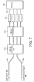
- Fig. 7 is a depiction of an optical heterodyne detection system that includes an optical combining unit, an optical pre-selector, and four photodetectors in accordance with the invention.
- Fig. 8 is an expanded view of the optical combining unit of Fig. 7 that includes two beams output from a coupler and split by a polarizing beam splitter in accordance with the invention.
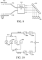
- Fig. 9 is a depiction of an example optical pre-selector in relation to the optical combining unit and four photodetectors that is related to the systems depicted in Figs. 7 and 8 in accordance with the invention.
- Fig. 10 is a graphical depiction of the signal processing that is performed on the electrical signals that are generated from the system of Figs. 7 and 8 in accordance with the invention.
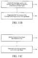
- Fig. 11A is a process flow diagram of a method for monitoring an input signal utilizing optical heterodyne detection that includes optical pre-selection.
- Fig. 11B is a process flow diagram of process steps related to the process flow diagram of Fig. 11A.
- Fig. 11C is a process flow diagram of process steps related to the process flow diagram of Fig. 11A.
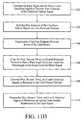
- Fig. 11D is a process flow diagram of process steps related to the process flow diagram of Fig. 11A.
- Fig. 12 is a process flow diagram of processing steps related to the process flow diagram of Fig. 11A.
- Fig. 13 is a depiction of an optical heterodyne detection system that includes two intensity noise reducers, a local oscillator amplifier, and an optical combining unit in accordance with the invention.
- Fig. 14 is a depiction of an optical heterodyne detection system that includes two intensity noise reducers, a local oscillator amplifier, an optical combining unit, and an optical pre-selector in accordance with the invention.
- Fig. 15A is a process flow diagram of a method for monitoring an input signal utilizing optical heterodyne detection that includes intensity noise reduction.
- Fig. 15B is a process flow diagram of a process step related to the process flow diagram of Fig. 12A.
- Fig. 15C is a process flow diagram of a process step related to the process flow diagram of Fig. 12A.
- Fig. 15D is a process flow diagram of a process step related to the process flow diagram of Fig. 12A.
- Fig. 16 is a depiction of an example intensity noise reducer that may be utilized with the systems of Figs. 13 and 14.
- Fig. 17 is a depiction of an example intensity noise reducer that may be utilized with the systems of Figs. 13 and 14.
- Fig. 18 is a graph of the power spectral density of an input signal vs. frequency after the intensity noise has been reduced by the intensity noise reducer of Fig. 17.
- An embodiment of the invention involves an optical heterodyne detection system in which an input signal and a swept local oscillator signal are combined and output as at least two beams. The at least two beams are filtered by a filter that passes a wavelength band that tracks the wavelength of the swept local oscillator signal. As the local oscillator signal sweeps across a wavelength range, filtering of the at least two beams is adjusted to track the wavelength of the local oscillator signal. Filtering the beams to pass a wavelength band corresponding to the wavelength of the swept local oscillator signal reduces the intensity noise contributed from light sources having wavelengths that are not near the wavelength of the local oscillator signal.
- Fig. 2 depicts an optical heterodyne detection system that includes an
input signal 202, asignal fiber 204, alocal oscillator signal 206, alocal oscillator fiber 208, anoptical combining unit 210, anoptical pre-selector 214, twophotodetectors 212, and aprocessor 216. It should be noted that throughout the description similar element numbers are utilized to identify similar elements. - The
input signal 202 and thelocal oscillator signal 206 include optical signals that are generated from conventional devices as is known in the field of optical communications systems. For example, the input signal and the local oscillator signal may be generated by lasers. The input signal may consist of a single wavelength or the input signal may include multiple wavelengths as is known in the field of wavelength division multiplexing (WDM). The input signal may be an optical signal having unknown optical characteristics, in which case the optical heterodyne detection system can be utilized for optical spectrum analysis. The input signal may alternatively be a delayed portion of the local oscillator signal that is utilized for optical network analysis. When the monitoring system is being utilized for optical network analysis, the characteristics of a network or a single network component can be determined by inputting a known input signal into the network or the single network component and then measuring the response to the known signal. - Preferably, the
local oscillator signal 206 is a widely tunable optical signal generated from a wideband tunable laser. For example, the local oscillator signal may be tunable over a range of one nanometer or greater. During optical spectrum analysis, the local oscillator signal is typically swept across a wavelength range in order to detect the input signal over a range of wavelengths. - The
signal fiber 204 carries theinput signal 202 that is to be detected by the system. In an embodiment, the signal fiber is a single mode optical fiber as is known in the art, although other optical waveguides may be utilized. In addition, although waveguides are described, optical signals may be input into the system, or transmitted within the system, in free space. - The
local oscillator fiber 208 is an optical fiber, such as a single mode optical fiber, that carries thelocal oscillator signal 206. The local oscillator fiber may include a polarization controller (not shown) that controls the polarization state of the local oscillator signal. Other optical waveguides may be utilized in place of single mode optical fiber, such as polarization preserving fiber. Alternatively, the local oscillator signal may be transmitted through free space without the use of a waveguide. - The
optical combining unit 210 optically combines theinput signal 202 and thelocal oscillator signal 206 into a combined optical signal and outputs at least two beams of the combined optical signal. The combined optical signal includes the heterodyne signal and intensity noise from the input signal and from the local oscillator signal. In an embodiment, the input signal and the local oscillator signal are combined in a manner that ensures the spatial overlap of the input signal and the local oscillator signal, thereby allowing full interference between the input signal and the local oscillator signal. - In an embodiment, the optical combining unit includes a coupler that outputs the combined optical signal into two optical paths. In another embodiment, the optical combining unit includes a coupler and a polarizing beam splitter that outputs two polarized portions of the combined optical signal. Although the optical combining unit is described below as outputting two beams of the combined optical signal, it should be understood that embodiments of the optical combining unit that output more than two beams of the combined optical signal are possible.
- Fig. 3 is a depiction of an embodiment of the optical combining
unit 210 in which the optical combining unit includes anoptical coupler 320 that has two outputs represented by twooutput fibers optical signal - The
optical coupler 320 in Fig. 3 may be an optically directional 3dB fiber coupler, although other optical couplers may be utilized. In an embodiment, the optical coupler is substantially independent of the polarization of optical signals. In an embodiment, the optical coupler does not polarize the combined optical signal. - Fig. 4 is a depiction of an embodiment of the optical combining
unit 210 in which the optical combining unit includes anoptical coupler 420, apolarizing beam splitter 424, and a half-wave plate 426. The optical coupler combines theinput signal 402 and thelocal oscillator signal 406 onto at least one waveguide. As shown in Fig. 4, the optical coupler combines the input signal and the local oscillator signal and outputs the combined optical signal intooutput fiber 428. It should be noted that althoughoutput fiber 418 is shown, there may not be two outputs from thecoupler 420. In an embodiment, the length of theoutput fiber 428 is chosen to provide sufficient attenuation of any cladding modes before the light of the input signal or the local oscillator signal reaches the end of the output fiber. For example, the length of the output fiber should be chosen such that cladding mode light accounts for less than one percent of the total light emitted from the output fiber. - The
polarizing beam splitter 424 separates an incoming optical beam into two polarized beams so that an output signal that is independent of the polarization state of the input signal can be generated. The polarizing beam splitter may include, for example, a birefringent crystal that provides polarization walk-off, such as a rutile walk-off crystal. As will be described below, the polarizing beam splitter separates the combined optical signal beam into two beams having different polarization states. Preferably, the polarizing beam splitter separates the incoming beam into two linearly polarized components that have orthogonal directions of polarization. In an embodiment, the polarization of the local oscillator signal is controlled such that the power contributed from the local oscillator signal is split approximately evenly by the polarizing beam splitter. Although theoptical coupler 420 and the polarizing beam splitter are shown as physically separate devices connected byoptical fiber 428, the optical coupler and polarizing beam splitter may be integrated into a planar waveguide circuit that does not require optical fiber connections. It should be understood that other polarizing beam splitters may be utilized. - Fig. 4 shows how the beam of the combined optical signal carried on
output fiber 428 is split into two differently polarized beams, as identified by the dashedlines straight line beam 440 follows an "ordinary" path and is referred to as the ordinary beam. Thediagonal line beam 442 walks off in an "extraordinary" path and is referred to as the extraordinary beam. - In a preferred embodiment, the two
polarized beams extraordinary beam 442 is rotated to match the polarization state of theordinary beam 440. When the two beams have orthogonal polarization, the extraordinary beam is rotated by 90 degrees. In an embodiment, a half-wave plate 426 is utilized to accomplish the 90-degree rotation. Although Fig. 4 represents one arrangement for generating two beams with the same polarization state, other arrangements may alternatively be utilized within the optical combiningunit 210 as would be apparent to one of ordinary skill in the field of optical communications systems. - Whether the optical combining unit involves the embodiment of Fig. 3 or the embodiment of Fig. 4, the end result is that two beams are output from the optical combining unit to the optical pre-selector. Referring back to Fig. 2, the
optical pre-selector 214 is a tunable bandpass filter that is tuned to track the sweptlocal oscillator signal 206. That is, the optical pre-selector is tuned so that the optical pre-selector has the highest optical transmission over a wavelength band that corresponds to the wavelength of the swept local oscillator signal. In an embodiment, the optical pre-selector is located between the optical combiningunit 210 and the twophotodetectors 212. - Operation of the
optical pre-selector 214 in a WDM system is depicted in the signal power vs. wavelength graphs of Figs. 5 and 6. Fig. 5 depicts aninput signal 502 as threeoptical carriers local oscillator signal 514 before the combined input signal and swept local oscillator signal have entered the optical pre-selector. For example purposes, the dashedline 518 represents the passband of the optical pre-selector that is tuned to track the sweep of the local oscillator signals. Optical signals within the passband continue to be transmitted and optical signals outside of the passband are filtered by the optical pre-selector. - Fig. 6 depicts the one
optical carrier 608 that exits the optical pre-selector after the optical signals have been filtered. As shown by Fig. 6, the optical pre-selector filters out optical carriers that are not near the wavelength of the swept local oscillator signal 614 (i.e., outside the passband of the optical pre-selector). The optical carriers that are not near the wavelength of the swept local oscillator signal are not necessary for optical heterodyne detection and only contribute to noise in the detection system if not filtered. Optical bandpass filtering that tracks the wavelength of the swept local oscillator signal is especially useful when measuring broadband optical noise, such as amplified spontaneous emissions from an optical amplifier. - Tunable optical pre-selectors, such as those described with reference to Figs. 2, 5, and 6 are well known in the field of optical communications and can be implemented utilizing components such as diffraction gratings, dielectric interference filters, Fabry-Perot interferometers, and other known interferometers. The embodiment of Fig. 2 has the
optical pre-selector 214 located between the optical combiningunit 210 and thephotodetectors 212 because the polarization states of the beams can be directly controlled to provide beams with known polarization states. Reliable bandpass filtering techniques can be utilized to filter beams having known polarization states. Although the arrangement of Fig. 2 is preferred, the optical pre-selector can be placed in other locations, such a location along the optical path of the swept local oscillator signal that is before the optical combining unit, a location along the optical path of the input signal that is before the optical combining unit, or both locations. - Referring to Fig. 2, the two
photodetectors 212 are aligned to separately detect the two filtered beams that are output from theoptical pre-selector 214. The two photodetectors generate electrical signals in response to a corresponding one of the two filtered beams. The electrical signals generated by each of the two photodetectors are individually provided to theprocessor 216. The two connections between the photodetectors and the processor are depicted in Fig. 2 by twolines 252. Although the two photodetectors are depicted as two independent photodetectors, the two photodetectors may be combined into a single unit. Although not shown, the photodetectors may include additional circuitry such as signal amplifiers and filters, as is known in the field. - The
processor 216 receives the electrical signals from the twophotodetectors 212 and processes the electrical signals into useful data. The processor may include analog signal processing circuitry and/or digital signal processing circuitry as is known in the field of electrical signal processing. In an embodiment, analog signals from the photodetectors are converted into digital signals and the digital signals are subsequently processed. It should be understood that digital signal processing involves converting the electrical signals from the photodetectors into digital signals that are representative of the original electrical signals. - Operation of the optical heterodyne detection system described with reference to Figs. 2 and 3 involves combining an input signal and a swept local oscillator signal into a combined optical signal and outputting two beams of the combined optical signal to the
optical pre-selector 214. The two beams are then filtered by theoptical pre-selector 214. The optical pre-selector passes a wavelength band that tracks the swept local oscillator signal. The two filtered beams are then detected by the twophotodetectors 212. The two photodetectors generate electrical signals in proportion to the intensity of the optical beams that are detected. The electrical signals generated by the two photodetectors are then received by theprocessor 216 and processed in a manner that maximizes the signal to noise ratio of the heterodyne term of the combined optical signal. Processing of the electrical signals may involve providing intensity noise suppression. Preferably, during operation, the center wavelength of the optical pre-selector passband tracks, in real-time, the wavelength of the swept local oscillator signal. As is described below, the system may require an initial calibration operation in order to provide accurate results. - Operation of the optical heterodyne detection system described with reference to Figs. 2 and 4 involves combining an input signal and a swept local oscillator signal into a combined optical signal, outputting one beam from the optical coupler, and then splitting the beam that is output from the optical coupler into two polarized beams. As described above, the combined optical signal that is output from the optical coupler is split into two polarized beams having different polarization states. The polarization state of the extraordinary portion of the split beam is then rotated so that the two polarized beams have the same polarization state. The two beams are then filtered by the
optical pre-selector 214. The optical pre-selector passes a wavelength band that tracks the swept local oscillator signal. The two polarized and filtered beams are then detected by the twophotodetectors 212. The two photodetectors generate electrical signals in proportion to the intensity of the optical beams that are detected. The electrical signals generated by the two photodetectors are then received by theprocessor 216 and processed in a manner that maximizes the signal to noise ratio of the heterodyne term of the combined optical signal. Processing of the electrical signals may involve squaring the electrical signals from the two photodetectors and then adding the two squared terms to generate an output signal that is independent of the polarization state of the input signal. Preferably, during operation, the center wavelength of the optical pre-selector passband tracks, in real-time, the wavelength of the swept local oscillator signal. - Whether or not the optical combining unit includes a polarizing beam splitter, the combination of the optical combining unit, the optical pre-selector, and the photodetectors creates an optical heterodyne detection system that filters the optical signals to reduce noise and improve the dynamic range of the system.
- As described above, the optical heterodyne detection system of Fig. 2 may include more than two beams being output from the optical combining
unit 210. Fig. 7 is a depiction of an optical heterodyne detection system that includes four beams being output from the optical combining unit. - Fig. 8 is an expanded view of an embodiment of an optical combining unit that outputs four polarized beams. The optical combining unit of Fig. 8 includes an
optical coupler 820, twooutput fibers polarizing beam splitter 824, and two half-wave plates 826. As shown in Fig. 8, the optical coupler combines the input signal and the local oscillator signal and distributes the combined optical signal into the twooutput fibers polarizing beam splitter 824. Preferably, the power of the combined optical signal is distributed approximately evenly between the two output fibers. Theoptical coupler 820 may be an optically directional 3dB fiber coupler, although other optical couplers may be utilized. In an embodiment, the optical coupler is substantially independent of the polarization of optical signals. In an embodiment, the optical coupler does not polarize the combined optical signal. - The
polarizing beam splitter 824 splits each of the combined optical signal beams from theoutput fibers - Fig. 8 shows how the two beams of the combined optical signal are each split into two differently polarized beams, as identified by the dashed
lines - In a preferred embodiment, each of the four
polarized beams extraordinary beams wave plates 826 are utilized to accomplish a 90-degree rotation. Although Fig. 8 represents one arrangement for generating four beams with the same polarization state, other arrangements may alternatively be utilized within the optical combiningunit 710 as would be apparent to one of ordinary skill in the field of optical communications systems. - Referring back to Fig. 7, the
optical pre-selector 714 includes a tunable bandpass filter that is tuned to track the sweptlocal oscillator signal 706. An embodiment of an optical pre-selector that includes a tunable diffraction grating is described in detail with reference to Fig. 9. As shown in Fig. 9, four beams having the same polarization state exit the optical combiningunit 910 and contact thetunable diffraction grating 914. The tunable diffraction grating is tuned to pass a wavelength band that tracks the wavelength of the sweptlocal oscillator signal 906. In an embodiment, the diffraction grating is tuned by adjusting the angle of the diffraction grating. The filtered beams that reflect off of the diffraction grating are directed to the fourphotodetectors 912 for optical detection. A tunable diffraction grating may be utilized in the same fashion in embodiments that include only two beams and two photodetectors. - Referring again to Fig. 7, the four
photodetectors 712 are aligned to separately detect the four polarized and filtered beams that are output from theoptical pre-selector 714. Each of the four photodetectors generates an electrical signal in response to a corresponding one of the four polarized and filtered beams. The electrical signal generated by each of the four photodetectors is individually provided to theprocessor 716. Theprocessor 716 receives the electrical signals from the fourphotodetectors 712 and processes the electrical signals into useful data. - Operation of the optical heterodyne detection system described with reference to Figs. 7 and 8 involves combining an input signal and a swept local oscillator signal into a combined optical signal and outputting two beams of the combined optical signal from the optical coupler. Each of the two beams containing the combined optical signal is then split into two polarized beams having different polarization states. The polarization states of the extraordinary portions of the split beams are then rotated so that all four beams have the same polarization state. The four beams are then filtered by the
optical pre-selector 714. The optical pre-selector passes a wavelength band that tracks the wavelength of the swept local oscillator signal. The passband of the optical pre-selector is tuned in real-time to track the wavelength of the local oscillator signal. The four polarized and filtered beams are then detected by the fourphotodetectors 712. The four photodetectors generate electrical signals in proportion to the intensity of the optical beams that are detected. The electrical signals generated by the four photodetectors are then received by theprocessor 716 and processed in a manner that maximizes the signal to noise ratio of the heterodyne term of the combined optical signal. Processing of the electrical signals may involve providing intensity noise suppression and polarization independence. - Fig. 10 is an example graphical depiction of how the electrical signals generated by a system with four photodetectors are processed to achieve intensity noise suppression and polarization diversity. The signal processing preferably involves digital signal processing although this is not critical. As shown in Fig. 10, the
photodetectors 1044 and 1046 are partially identified by "1," which corresponds to the beam (beam 1) that is output from thefirst output fiber 818 of theoptical coupler 820 as shown in Fig. 8. Thephotodetectors second output fiber 828 of the optical coupler shown in Fig. 8. The twophotodetectors 1046 and 1050 that receive the ordinary portions of the split beams are partially identified by the letter "o," which corresponds to the ordinary beams exiting from the optical combining unit. The twophotodetectors - Initially, signal subtractions are performed between the "1o" signal and the "2o" signal, and between the "1e" signal and the "2e" signal. The subtraction functions are represented by
subtraction units - Additional signal processing is implemented on the subtracted signals to provide polarization diversity. Because the combined optical signal beams are split into orthogonal states of polarization, one of the beams is proportional to cos and the other beam is proportional to sin, where is the angle of polarization of the input signal. In the example of Fig. 10, the electrical signals generated from the ordinary beam portions include a cos term and the electrical signals generated from the extraordinary beam portions include a sin term. The cos term is squared, as represented by squaring
unit 1058, and the sin term is squared, as represented by squaringunit 1060. The squaring units generate output signals that are proportional to the square of the input signals. In an embodiment, the output signals from the squaring units are each connected to lowpass filtering units 1064 and 1068 although the low pass filtering units may not be critical. The low pass filtering units provide low pass filtering on the squared output signals. The output signals from the low pass filtering units are each connected to an input terminal of an adder unit, designated 1070, which produces a readout signal that is proportional to the sum of the signals from the low pass filtering units. Squaring the cos term and the sin term, low pass filtering the terms, and then adding the squared and filtered cos term to the squared and filtered sin term provides a result that is independent of the angle of polarization () of the input signal and therefore polarization diverse. - In the embodiment described with reference to Fig. 3, the subtraction function is performed to electronically reduce the intensity noise, however the squaring and adding functions are not used. In the embodiment described with reference to Fig. 4, the squaring and adding functions are performed to provide a result that is independent of the angle of polarization of the input signal, however the subtraction function is not used. It should be understood that in a digital system the subtracting, squaring, low pass filtering, and adding units may be incorporated into a multifunction processor.
- Referring back to Fig. 7, the combination of the optical combining
unit 710, theoptical pre-selector 714, the fourphotodetectors 712, theprocessor 716, includingunits - A method for monitoring an optical signal utilizing an optical heterodyne detection system with optical pre-selection is described herein and depicted in the process flow diagram of Fig. 11A. In a
step 1102, an input signal is combined with a swept local oscillator signal to generate a combined optical signal. In astep 1104, light beams are output with each light beam including a portion of the combined optical signal. In astep 1106 each of the light beams is filtered to pass a wavelength band that tracks the wavelength of the swept local oscillator signal, wherein the filtering generates filtered portions of the light beams. In astep 1108, electrical signals are generated in response to the filtered portions of the light beams. In astep 1110, the electrical signals are processed to determine an optical characteristic represented by the input signal. - An embodiment of the method depicted in Fig. 11A includes details of
steps step 1102 the input signal and the swept local oscillator signal are combined to generate two instances of the combined optical signal and instep 1104 each of the two instances of the combined optical signal is output as one of the light beams. - Another embodiment of the method depicted in Fig. 11A includes an additional step and details of
step 1104. Referring to Fig. 11C, instep 1118 the combined optical signal is split into polarized portions and instep 1104 each of the polarized portions is output as one of the light beams. - Another embodiment of the method depicted in Fig. 11A includes details of steps 1102 - 1110 and an additional step. Referring to Fig. 11D, in
step 1102 the input signal and the swept local oscillator signal are combined to generate two instances of the combined optical signal. Instep 1126, the two instances of the combined optical signal are split into two polarized portions. Instep 1104, each of the four polarized portions is output as one of the light beams. Atstep 1106, the first, second, third, and fourth polarized portions are filtered to pass a wavelength band that tracks the wavelength of the swept local oscillator signal. Instep 1108, first, second, third, and fourth electrical signals are generated in response to the filtered portions of the first, second, third, and fourth light beams. In astep 1110, the first, second, third, and fourth electrical signals are processed to determine an optical characteristic represented by the input signal. - Details of the processing for the method step described in
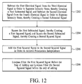
step 1110 of Fig. 11D are represented in Fig. 12. In astep 1202, the processing involves subtracting the first electrical signal from the third electrical signal in order to suppress intensity noise, thereby creating a first subtracted signal, and subtracting the second electrical signal from the fourth electrical signal in order to suppress intensity noise, thereby creating a second subtracted signal. It should be noted that these process steps are not utilized when the combined optical signal is split into only two polarized beams. - In an
additional step 1204, the processing further involves squaring the first subtracted signal, thereby creating a first squared signal, and squaring the second subtracted signal, thereby creating a second squared signal. - In an
additional step 1206, the processing further involves adding the first squared signal to the second squared signal in order to achieve polarization independence. - In an additional
related step 1208, the processing further involves low pass filtering the first squared signal before the step of adding and low pass filtering the second squared signal before the step of adding. - In an embodiment, the filtering of the beams is adjusted in real-time to track the wavelength change of the swept local oscillator signal. In an embodiment, the intensity noise of the input signal is reduced before the input signal is combined with the swept local oscillator signal. In an embodiment, the intensity noise of the swept local oscillator signal is reduced before the swept local oscillator signal is combined with the input signal. In an embodiment, the swept local oscillator signal is amplified before the intensity noise of the swept local oscillator signal is reduced.
- An embodiment of an optical heterodyne detection system that is similar to the systems and method that are described with reference to Figs. 2 - 12 may include a switch associated with the signal fiber. The switch is utilized to selectively block transmission of the input signal in order to calibrate the system. For example, while the input signal is switched off, the coupling coefficient of the optical combing unit can be determined as a function of wavelength by sweeping the local oscillator signal across a range of wavelengths. In addition, the responsivity of the photodetectors can be determined as a function of wavelength by sweeping the local oscillator signal while the input signal is switched off.
- Further, the distribution of the local oscillator signal onto the photodetectors can be determined as a function of wavelength by sweeping the local oscillator signal while the input signal is switched off. It is preferable that the local oscillator signal is approximately evenly distributed among the photodetectors. If the local oscillator signal is not evenly distributed among the photodetectors, then the power distribution of the local oscillator signal may be adjusted utilizing a polarization controller.
- Another embodiment of the invention involves an optical heterodyne detection system in which the intensity noise of the input signal and/or the intensity noise of the swept local oscillator signal is reduced before the input signal and the swept local oscillator signal are combined. An embodiment of the optical heterodyne detection system is depicted in Fig. 13 and includes an
input signal 1302, asignal fiber 1304, anintensity noise reducer 1376 on the signal fiber, alocal oscillator signal 1306, alocal oscillator fiber 1308, anoptical amplifier 1380 and anintensity noise reducer 1378 on the local oscillator fiber, anoptical combining unit 1310, twophotodetectors 1312, and aprocessor 1316. The system of Fig. 13 does not include an optical pre-selector as described with reference to the system of Fig. 2. Elements shown in Fig. 13 that are similar to elements shown in Fig. 2 are identified by similar element numbers. In addition, the above-provided descriptions apply to similar elements in Fig. 13. Operation of the optical heterodyne detection system of Fig. 13 is also similar to the system of Fig. 2 except that there is no optical pre-selection. - While the embodiment of Fig. 13 includes the two
intensity noise reducers optical amplifier 1380 on the same system, other embodiments of the optical heterodyne detection system may include any combination of the intensity noise reducers and the optical amplifier. For example, an embodiment of the system may include theintensity noise reducer 1376 on thesignal fiber 1304 and no intensity noise reducer on thelocal oscillator fiber 1308. Conversely, an embodiment may include theintensity noise reducer 1378 on the local oscillator fiber and no intensity noise reducer on the signal fiber. In addition, although the intensity noise reducers are located before theoptical combining unit 1310, the intensity noise reducers may be placed in other locations within the optical heterodyne detection system. - As described above, utilizing
intensity noise reducers input fiber 1304 and/or thelocal oscillator fiber 1308 reduces the intensity noise that is detected by thephotodetectors 1312 and improves the signal to noise ratio and the dynamic range of the heterodyne detection system. Optical intensity noise reduction can be accomplished utilizing various techniques. Example intensity noise reduction systems are described below with reference to Fig. 16 - 18. - The
optical amplifier 1380 on thelocal oscillator fiber 1308 is utilized to increase the power of thelocal oscillator signal 1306, thereby improving the signal to noise ratio and dynamic range of the heterodyne detection system. An erbium doped fiber amplifier may be utilized to amplify the local oscillator signal. Theintensity noise reducer 1378 on the local oscillator fiber should be utilized when the optical amplifier is utilized in order to control the additional intensity noise that is contributed by the optical amplifier. - While the embodiment of Fig. 13 includes intensity noise reduction for the
input signal 1302 and/or thelocal oscillator signal 1306, it does not include the optical pre-selector as described above with regard to the optical heterodyne detection system of Fig. 2. An optical pre-selector can be added to the system of Fig. 13 to create the system that is depicted in Fig. 14. The system depicted in Fig. 14 includes anintensity noise reducer 1476 on theinput fiber 1404, anintensity noise reducer 1478 and anoptical amplifier 1480 on thelocal oscillator fiber 1408, and anoptical pre-selector 1414 located between theoptical combining unit 1410 and thephotodetectors 1412. The system of Fig. 14 operates similarly to the systems described with reference to Figs. 2 and 13. Although Fig. 14 includes an optical combining unit and two photodetectors, the system may alternatively include more than two beams exiting the optical combining unit along with corresponding photodetectors. - Although the two
intensity noise reducers optical amplifier 1480 shown in Fig. 14 are depicted as parts of the same system, it should be understood that any combination of the intensity noise reducers and the optical amplifier may be implemented in a particular system. For example, an embodiment may include only an intensity noise reducer on the input fiber, or only an intensity noise reducer on the local oscillator fiber, or the intensity noise reducer and the optical amplifier on the local oscillator fiber and no intensity noise reducer on the input fiber. In addition, although the intensity noise reducers are located before theoptical combining unit 1410, the intensity noise reducers may be placed in other locations within the optical heterodyne detection system. - Utilizing
intensity noise reducers input fiber 1404 and/or thelocal oscillator fiber 1408 in conjunction with theoptical pre-selector 1414 reduces the intensity noise that is detected by thephotodetectors 1412 and improves the signal to noise ratio and the dynamic range of the heterodyne detection system. - A method for monitoring an optical signal utilizing an optical heterodyne detection system with intensity noise reduction is depicted in the process flow diagram of Fig. 15A. In a
step 1502, the intensity noise of a first signal is reduced. In astep 1504, the noise reduced first signal is combined with a second signal to generate a combined optical signal. One of the first and second signals is a swept local oscillator signal and the other signal is an input signal. In astep 1506, light beams are output, wherein the light beams each include a portion of the combined optical signal. In astep 1508, electrical signals are generated in response to the light beams. In astep 1510, the electrical signals are processed to determine an optical characteristic represented by the input signal. - An embodiment of the method depicted in Fig. 15A includes an
additional step 1514 of reducing the intensity noise of the second signal before the second signal is combined with the reduced first signal as shown in Fig. 15B. - An embodiment of the method depicted in Fig. 15A includes an
additional step 1516 of amplifying the first signal before the intensity noise of the first signal is reduced as shown in Fig. 15C. - An embodiment of the method depicted in Fig. 15A includes an
additional step 1518 of filtering the light beams before the electrical signals are generated as shown in Fig. 15D. - An embodiment of the method depicted in Fig. 15A includes details of
steps - Another embodiment of the method depicted in Fig. 15A includes an additional step and details of
step 1506. Referring back to Fig. 11C, instep 1118 the combined optical signal is split into polarized portions and instep 1104 each of the polarized portions is output as one of the light beams. - Another embodiment of the method depicted in Fig. 15A includes details of
steps step 1106. The above-provided description of the steps in Fig. 11D relates to the process of Fig. 15A and is therefore not repeated. - Details of the processing recited in
step 1510 of Fig. 15A are represented in Fig. 12. The above-provided description of the steps in Fig. 12 relates to the process of Fig. 15A and is therefore not repeated. - Although other intensity noise reducers may be utilized in the systems and methods described with reference to Figs. 2 - 15, example embodiments of intensity noise reducers are depicted in Figs. 16 and 17. The
intensity noise reducer 1684 of Fig. 16 can be utilized on the signal fiber and/or thelocal oscillator fiber 1686. In the example shown, the intensity noise reducer is included in thelocal oscillator fiber 1686 and the system includes acoupler 1688, aphotodetector 1690, afeedback system 1692, and anamplitude modulator 1694. Intensity noise is reduced by sampling the incoming signal to measure the intensity noise and then amplitude modulating the incoming signal to smooth out the intensity noise. The amplitude modulator may include a LiNbO3 modulator, an acousto-optic modulator, an optical semiconductor amplifier, or any other device that can change the transmission of the incoming signal in response to a feedback signal. - The
intensity noise reducer 1784 of Fig. 17 can be utilized on the signal fiber and/or thelocal oscillator fiber 1786. In the example shown, the intensity noise reducer is included in thelocal oscillator fiber 1786 and the system includes aninput fiber 1788, anoutput fiber 1790, afirst delay fiber 1791, asecond delay fiber 1792, acoupler 1793, adelay unit 1794, aFaraday mirror 1795, a half-wave plate rotated at 45degrees 1796, and anordinary mirror 1797. In an embodiment, the input fiber is polarization maintaining fiber and the incoming signal (either the input signal or the local oscillator signal) is at zero degrees relative to the polarization maintaining fiber. In operation, the Faraday mirror on the first delay fiber and the half-waveplate and mirror on the second delay fiber create two delayed signals that have orthogonal polarizations. When the two delayed signals are combined there is no optical interference, however the intensity noise fluctuations within a predetermined frequency range are combined with 180 degrees of phase difference. Because the intensity noise fluctuations are 180 degrees out of phase, the intensity noise of the two delayed signals cancel out and the resulting signal on the output fiber has reduced intensity noise. The above-described intensity noise reduction technique can be implemented with other arrangements utilizing, for example, regular beam splitters, standard single mode fiber directional couplers, and Faraday mirrors. - Fig. 18 is a graph of the power spectral density of an input signal vs. frequency after the intensity noise has been reduced utilizing the intensity noise reducer as utilized in Fig. 17. The
solid line 1890 represents the filtered intensity noise and the dashedline 1892 represents the location of the heterodyne signal relative to the filtered intensity noise.
Claims (10)
- A system for optical heterodyne detection comprising:an intensity noise reducer (1376,1378) for reducing the intensity noise of a first signal;an optical combining unit (1310) for combining said noise reduced first signal and a second signal into a combined optical signal and for outputting light beams each including a portion of said combined optical signal, one of said first and second signals being a swept local oscillator signal; andphotodetectors (1312) each optically arranged to receive a different one of said light beams, said photodetectors generating electrical signals in response to respective ones of said light beams.
- The system of claim 1 further including an intensity noise reducer (1376, 1378) for reducing the intensity noise of said second signal.
- The system of claim 1 or 2 further including an amplifier (1380) located in an optical path before said intensity noise reducer of said first signal.
- The system of one of the preceding claims further including an optical pre-selector (1414) optically connected to receive said light beams from said optical combining unit, said optical pre-selector having a passband that tracks the wavelength of said swept local oscillator signal, said optical pre-selector outputting filtered portions of said light beams to said photodetectors.
- The system of one of the preceding claims further including a processor (1316), arranged to receive said electrical signals, for generating an output signal that is substantially independent of the polarization of said first and second signals.
- A method for monitoring an optical signal utilizing optical heterodyne detection comprising steps of:reducing (1502) the intensity noise of a first signal;combining (1504) said noise reduced first signal with a second signal to generate a combined optical signal, one of said first and second signals being a swept local oscillator signal and the other signal being an input signal;outputting (1506) light beams each including a portion of said combined optical signal;generating (1508) electrical signals in response to said light beams; andprocessing (1510) said electrical signals to determine an optical characteristic represented by said input signal.
- The method of claim 6 further including a step of reducing (1514) the intensity noise of said second signal before said second signal is combined with said noise reduced first signal.
- The method of claim 6 or 7 further including a step of amplifying (1516) said first signal before said step of reducing the intensity noise of said first signal.
- The method of one of claims 6 - 8 further including a step of, before said electrical signals are generated, filtering (1518) said light beams to pass a wavelength band that tracks the wavelength of said swept local oscillator signal.
- The method of one of claims 6 - 9, in which:the method additionally comprises splitting (1118) said combined optical signal into polarized portions; andin outputting (1104) said light beams, each of said polarized portions is output as one of said light beams.
Applications Claiming Priority (2)
| Application Number | Priority Date | Filing Date | Title |
|---|---|---|---|
| US09/506,195 US6256103B1 (en) | 2000-02-17 | 2000-02-17 | System and method for optical heterodyne detection of an optical signal |
| US506195 | 2000-02-17 |
Publications (2)
| Publication Number | Publication Date |
|---|---|
| EP1130816A2 true EP1130816A2 (en) | 2001-09-05 |
| EP1130816A3 EP1130816A3 (en) | 2004-09-22 |
Family
ID=24013586
Family Applications (1)
| Application Number | Title | Priority Date | Filing Date |
|---|---|---|---|
| EP00123548A Withdrawn EP1130816A3 (en) | 2000-02-17 | 2000-10-27 | System and method for optical heterodyne detection of an optical signal |
Country Status (3)
| Country | Link |
|---|---|
| US (1) | US6256103B1 (en) |
| EP (1) | EP1130816A3 (en) |
| JP (1) | JP2001281105A (en) |
Cited By (1)
| Publication number | Priority date | Publication date | Assignee | Title |
|---|---|---|---|---|
| WO2012130275A1 (en) * | 2011-03-28 | 2012-10-04 | Agilent Technologies, Inc. | Heterodyne optical spectrum analyzer |
Families Citing this family (15)
| Publication number | Priority date | Publication date | Assignee | Title |
|---|---|---|---|---|
| US6535289B1 (en) * | 2000-06-02 | 2003-03-18 | Agilent Technologies, Inc. | System and method for optical heterodyne detection of an optical signal |
| US6646746B1 (en) * | 2000-10-02 | 2003-11-11 | Agilent Technologies, Inc. | Method and system for optical heterodyne detection of an optical signal |
| US6856400B1 (en) | 2000-12-14 | 2005-02-15 | Luna Technologies | Apparatus and method for the complete characterization of optical devices including loss, birefringence and dispersion effects |
| US20030016425A1 (en) * | 2001-07-19 | 2003-01-23 | Tan Tun Sein | Polarization diversity receiver with planar waveguide and polarizing beam splitter |
| US7272324B2 (en) * | 2001-10-26 | 2007-09-18 | Avago Technologies Fiber Ip (Singapore) Pte. Ltd. | Equalization of optical signals |
| US6853456B2 (en) * | 2002-01-31 | 2005-02-08 | Tip Group, Llc | Method and apparatus for measuring a frequency of an optical signal |
| US20040264981A1 (en) * | 2003-06-25 | 2004-12-30 | Tyco Telecommunications (Us) Inc. | Wavelength monitoring and control system |
| US7307734B2 (en) * | 2003-08-14 | 2007-12-11 | University Of Central Florida | Interferometric sensor for characterizing materials |
| US20050078317A1 (en) * | 2003-10-14 | 2005-04-14 | Law Joanne Y. | Synchronizing the filter wavelength of an optical filter with the wavelength of a swept local oscillator signal |
| US7466425B2 (en) * | 2005-04-22 | 2008-12-16 | Agilent Technologies, Inc. | Elementary matrix based optical signal/network analyzer |
| US9134479B2 (en) * | 2012-09-05 | 2015-09-15 | International Business Machines Corporation | Polarization diverse demultiplexing |
| WO2018197975A1 (en) | 2017-04-26 | 2018-11-01 | Exfo Inc. | Noise-free measurement of the spectral shape of a modulated signal using spectral correlation |
| US11614543B2 (en) * | 2018-10-09 | 2023-03-28 | GM Global Technology Operations LLC | Transimpedance amplifier for Lidar system |
| US11366206B2 (en) * | 2019-03-18 | 2022-06-21 | Aeva, Inc. | Lidar apparatus with an optical amplifier in the return path |
| CN110535461B (en) * | 2019-08-01 | 2022-12-09 | 上海大学 | Heterodyne detection device based on light injection locking and optical phase-locked loop |
Citations (3)
| Publication number | Priority date | Publication date | Assignee | Title |
|---|---|---|---|---|
| US4856093A (en) * | 1986-06-28 | 1989-08-08 | Alcatel N.V. | Optical heterodyne receiver |
| GB2214381A (en) * | 1987-12-29 | 1989-08-31 | Gen Electric Co Plc | Optical phase-diversity receivers |
| EP0491421A2 (en) * | 1990-12-17 | 1992-06-24 | Koninklijke Philips Electronics N.V. | Coherent optical multichannel receiver |
Family Cites Families (5)
| Publication number | Priority date | Publication date | Assignee | Title |
|---|---|---|---|---|
| US4856899A (en) | 1985-12-20 | 1989-08-15 | Yokogawa Electric Corporation | Optical frequency analyzer using a local oscillator heterodyne detection of incident light |
| DE4244605A1 (en) | 1992-05-27 | 1993-12-02 | Hewlett Packard Co | Optical low-coherence reflectometer with improved sensitivity with optical attenuation |
| NL9201130A (en) * | 1992-06-25 | 1994-01-17 | Nederland Ptt | OPTICAL MIXER WITH A PHOTODETECTOR FOR A HETERODYNE RECEIVER. |
| US5953139A (en) * | 1996-03-06 | 1999-09-14 | Cfx Communications Systems, Llc | Wavelength division multiplexing system |
| US5872624A (en) * | 1997-06-05 | 1999-02-16 | Gn Nettest (New York) | Method and apparatus for retroreflectively reducing coherence/polarization noise in reflectometers |
-
2000
- 2000-02-17 US US09/506,195 patent/US6256103B1/en not_active Expired - Fee Related
- 2000-10-27 EP EP00123548A patent/EP1130816A3/en not_active Withdrawn
-
2001
- 2001-02-19 JP JP2001042337A patent/JP2001281105A/en active Pending
Patent Citations (3)
| Publication number | Priority date | Publication date | Assignee | Title |
|---|---|---|---|---|
| US4856093A (en) * | 1986-06-28 | 1989-08-08 | Alcatel N.V. | Optical heterodyne receiver |
| GB2214381A (en) * | 1987-12-29 | 1989-08-31 | Gen Electric Co Plc | Optical phase-diversity receivers |
| EP0491421A2 (en) * | 1990-12-17 | 1992-06-24 | Koninklijke Philips Electronics N.V. | Coherent optical multichannel receiver |
Cited By (1)
| Publication number | Priority date | Publication date | Assignee | Title |
|---|---|---|---|---|
| WO2012130275A1 (en) * | 2011-03-28 | 2012-10-04 | Agilent Technologies, Inc. | Heterodyne optical spectrum analyzer |
Also Published As
| Publication number | Publication date |
|---|---|
| US6256103B1 (en) | 2001-07-03 |
| JP2001281105A (en) | 2001-10-10 |
| EP1130816A3 (en) | 2004-09-22 |
Similar Documents
| Publication | Publication Date | Title |
|---|---|---|
| US6259529B1 (en) | Wavelength-selective polarization-diverse optical heterodyne receiver | |
| US6256103B1 (en) | System and method for optical heterodyne detection of an optical signal | |
| US7027743B1 (en) | System and method for optical heterodyne detection of an optical signal including optical pre-selection that is adjusted to accurately track a local oscillator signal | |
| EP1278087B1 (en) | Polarization diversity receiver with planar waveguide and polarizing beam splitter | |
| EP1253730B1 (en) | Method and system for optical spectrum analysis with matched filter detection | |
| US6671056B2 (en) | Method and system for optical spectrum analysis with a depolarized local oscillator signal | |
| EP1130814B1 (en) | System and method for heterodyne detection of an optical signal | |
| US6590666B2 (en) | Method and system for optical spectrum analysis with non-uniform sweep rate correction | |
| US6535289B1 (en) | System and method for optical heterodyne detection of an optical signal | |
| JP2004147323A (en) | Heterodyne-based optical spectrum analysis of using controlled optical attenuation | |
| US7095963B2 (en) | Multi-channel optical receiver for processing tri-cell polarization diversity detector outputs | |
| US6977720B2 (en) | Characterization of active and passive optical properties of an optical device | |
| EP1130813B1 (en) | Method and system for optical heterodyne detection using optical attenuation | |
| US20030108267A1 (en) | Device for detecting the pmd of optoelectronic transmission lines | |
| US6646746B1 (en) | Method and system for optical heterodyne detection of an optical signal | |
| CN112104415A (en) | System for detecting Rayleigh scattering signal intensity by adopting EDFA (erbium doped fiber amplifier) | |
| JP3403643B2 (en) | Polarization-dependent precision measurement equipment |
Legal Events
| Date | Code | Title | Description |
|---|---|---|---|
| PUAI | Public reference made under article 153(3) epc to a published international application that has entered the european phase |
Free format text: ORIGINAL CODE: 0009012 |
|
| AK | Designated contracting states |
Kind code of ref document: A2 Designated state(s): AT BE CH CY DE DK ES FI FR GB GR IE IT LI LU MC NL PT SE |
|
| AX | Request for extension of the european patent |
Free format text: AL;LT;LV;MK;RO;SI |
|
| RAP1 | Party data changed (applicant data changed or rights of an application transferred) |
Owner name: AGILENT TECHNOLOGIES, INC. (A DELAWARE CORPORATION |
|
| PUAL | Search report despatched |
Free format text: ORIGINAL CODE: 0009013 |
|
| AK | Designated contracting states |
Kind code of ref document: A3 Designated state(s): AT BE CH CY DE DK ES FI FR GB GR IE IT LI LU MC NL PT SE |
|
| AX | Request for extension of the european patent |
Extension state: AL LT LV MK RO SI |
|
| 17P | Request for examination filed |
Effective date: 20050223 |
|
| AKX | Designation fees paid |
Designated state(s): DE FR GB |
|
| 17Q | First examination report despatched |
Effective date: 20060710 |
|
| RAP1 | Party data changed (applicant data changed or rights of an application transferred) |
Owner name: AGILENT TECHNOLOGIES, INC. |
|
| GRAP | Despatch of communication of intention to grant a patent |
Free format text: ORIGINAL CODE: EPIDOSNIGR1 |
|
| STAA | Information on the status of an ep patent application or granted ep patent |
Free format text: STATUS: THE APPLICATION IS DEEMED TO BE WITHDRAWN |
|
| 18D | Application deemed to be withdrawn |
Effective date: 20080318 |