EP1130815A2 - Récepteur hétérodyne optique en diversité de polarisation et sélectif en longeur d'onde - Google Patents
Récepteur hétérodyne optique en diversité de polarisation et sélectif en longeur d'onde Download PDFInfo
- Publication number
- EP1130815A2 EP1130815A2 EP00123257A EP00123257A EP1130815A2 EP 1130815 A2 EP1130815 A2 EP 1130815A2 EP 00123257 A EP00123257 A EP 00123257A EP 00123257 A EP00123257 A EP 00123257A EP 1130815 A2 EP1130815 A2 EP 1130815A2
- Authority
- EP
- European Patent Office
- Prior art keywords
- signal
- optical
- local oscillator
- combined
- light beams
- Prior art date
- Legal status (The legal status is an assumption and is not a legal conclusion. Google has not performed a legal analysis and makes no representation as to the accuracy of the status listed.)
- Withdrawn
Links
- 230000003287 optical effect Effects 0.000 title claims abstract description 354
- 238000001514 detection method Methods 0.000 claims abstract description 66
- 238000001914 filtration Methods 0.000 claims abstract description 25
- 238000012544 monitoring process Methods 0.000 claims abstract description 11
- 238000000034 method Methods 0.000 claims description 70
- 230000010287 polarization Effects 0.000 claims description 70
- 238000012545 processing Methods 0.000 claims description 21
- 230000004044 response Effects 0.000 claims description 11
- 239000003638 chemical reducing agent Substances 0.000 abstract description 40
- 239000000835 fiber Substances 0.000 description 66
- 230000008569 process Effects 0.000 description 22
- 238000010586 diagram Methods 0.000 description 18
- 230000009467 reduction Effects 0.000 description 7
- 239000013307 optical fiber Substances 0.000 description 6
- 230000003111 delayed effect Effects 0.000 description 4
- 230000003595 spectral effect Effects 0.000 description 4
- 230000001629 suppression Effects 0.000 description 4
- 230000005540 biological transmission Effects 0.000 description 3
- 239000000969 carrier Substances 0.000 description 3
- 230000008859 change Effects 0.000 description 3
- 238000010408 sweeping Methods 0.000 description 3
- UIAFKZKHHVMJGS-UHFFFAOYSA-N 2,4-dihydroxybenzoic acid Chemical compound OC(=O)C1=CC=C(O)C=C1O UIAFKZKHHVMJGS-UHFFFAOYSA-N 0.000 description 2
- 238000005253 cladding Methods 0.000 description 2
- 239000013078 crystal Substances 0.000 description 2
- 238000005259 measurement Methods 0.000 description 2
- 238000003012 network analysis Methods 0.000 description 2
- 230000035945 sensitivity Effects 0.000 description 2
- 238000001228 spectrum Methods 0.000 description 2
- 238000010183 spectrum analysis Methods 0.000 description 2
- 229910052691 Erbium Inorganic materials 0.000 description 1
- 229910003327 LiNbO3 Inorganic materials 0.000 description 1
- 230000003321 amplification Effects 0.000 description 1
- 230000008878 coupling Effects 0.000 description 1
- 238000010168 coupling process Methods 0.000 description 1
- 238000005859 coupling reaction Methods 0.000 description 1
- 230000001419 dependent effect Effects 0.000 description 1
- UYAHIZSMUZPPFV-UHFFFAOYSA-N erbium Chemical compound [Er] UYAHIZSMUZPPFV-UHFFFAOYSA-N 0.000 description 1
- 238000003199 nucleic acid amplification method Methods 0.000 description 1
- 238000005070 sampling Methods 0.000 description 1
- 239000004065 semiconductor Substances 0.000 description 1
- 230000002269 spontaneous effect Effects 0.000 description 1
- GWEVSGVZZGPLCZ-UHFFFAOYSA-N titanium dioxide Inorganic materials O=[Ti]=O GWEVSGVZZGPLCZ-UHFFFAOYSA-N 0.000 description 1
Images


Classifications
-
- H—ELECTRICITY
- H04—ELECTRIC COMMUNICATION TECHNIQUE
- H04B—TRANSMISSION
- H04B10/00—Transmission systems employing electromagnetic waves other than radio-waves, e.g. infrared, visible or ultraviolet light, or employing corpuscular radiation, e.g. quantum communication
- H04B10/60—Receivers
- H04B10/61—Coherent receivers
- H04B10/614—Coherent receivers comprising one or more polarization beam splitters, e.g. polarization multiplexed [PolMux] X-PSK coherent receivers, polarization diversity heterodyne coherent receivers
-
- H—ELECTRICITY
- H04—ELECTRIC COMMUNICATION TECHNIQUE
- H04B—TRANSMISSION
- H04B10/00—Transmission systems employing electromagnetic waves other than radio-waves, e.g. infrared, visible or ultraviolet light, or employing corpuscular radiation, e.g. quantum communication
- H04B10/60—Receivers
- H04B10/61—Coherent receivers
- H04B10/615—Arrangements affecting the optical part of the receiver
- H04B10/6151—Arrangements affecting the optical part of the receiver comprising a polarization controller at the receiver's input stage
-
- H—ELECTRICITY
- H04—ELECTRIC COMMUNICATION TECHNIQUE
- H04B—TRANSMISSION
- H04B10/00—Transmission systems employing electromagnetic waves other than radio-waves, e.g. infrared, visible or ultraviolet light, or employing corpuscular radiation, e.g. quantum communication
- H04B10/60—Receivers
- H04B10/61—Coherent receivers
- H04B10/64—Heterodyne, i.e. coherent receivers where, after the opto-electronic conversion, an electrical signal at an intermediate frequency [IF] is obtained
Definitions
- the invention relates generally to the field to optical measurements and measuring systems, and more particularly to a system and method for optical heterodyne detection of an optical signal.
- DWDM Dense wavelength division multiplexing
- OSAs optical spectrum analyzers
- grating-based OSAs and autocorrelation-based OSAs encounter mechanical constraints, such as constraints on beam size and the scanning of optical path lengths, which limit the degree of resolution that can be obtained.
- Fig. 1 is a depiction of a prior art optical heterodyne detection system.
- the optical heterodyne detection system includes an input signal 102, an input waveguide 104, a local oscillator signal 106, a local oscillator waveguide 108, an optical coupler 110, an output waveguide 118, a photodetector 112, and a signal processor 116.
- the principles of operation of optical heterodyne detection systems are well known in the field of optical heterodyne detection and involve monitoring the heterodyne term that is generated when an input signal is combined with a local oscillator signal.
- the heterodyne term coexists with other direct detection signals, such as intensity noise from the input signal and intensity noise from the local oscillator signal.
- Optical heterodyne detection systems are not limited by the mechanical constraints that limit the grating based and autocorrelation based OSAs.
- the spectral resolution of an optical heterodyne system is limited by the linewidth of the local oscillator signal, which can be several orders of magnitude narrower than the resolution of other OSAs.
- the heterodyne signal In order to improve the performance of optical heterodyne detection systems with regard to parameters such as sensitivity and dynamic range, it is best for the heterodyne signal to have a high signal to noise ratio.
- the signal to noise ratio of the heterodyne signal is often degraded by noise that is contributed by the direct detection signals, especially in the case where the input signal includes multiple carrier wavelengths.
- One technique for improving the signal to noise ratio of the heterodyne signal involves amplifying the input signal before the input signal is combined with the local oscillator signal in order to increase the amplitude of the heterodyne signal. Although amplifying the input signal increases the amplitude of the heterodyne signal, the amplification also increases the intensity noise of the input signal and may not improve the signal to noise ratio of the heterodyne signal.
- the polarization state of the local oscillator signal may be controlled by a polarization controller 120 as indicated by the two loops in the heterodyne detection system of Fig. 1.
- a disadvantage of the optical heterodyne detection system of Fig. 1 is that detection of the input signal is highly dependent on the polarization of the input signal.
- a polarization diversity receiver can be incorporated into an optical heterodyne detection system to provide polarization independent signal detection.
- a polarization diversity receiver provides polarization independent signal detection
- the polarization diversity receiver does not provide a way to separate the intensity noise from the heterodyne signal.
- it is necessary to be able to clearly distinguish the heterodyne signal from the intensity noise.
- optical heterodyne detection system that generates a heterodyne signal with an improved signal to noise ratio.
- a system for monitoring an optical signal includes an optical heterodyne detection system in which an input signal and a swept local oscillator signal are combined and output in at least two beams.
- the output beams are filtered by a filter having a passband which tracks the wavelength of the swept local oscillator signal.
- filtering of the output beams is adjusted to track the wavelength of the local oscillator signal. Filtering the output beams to pass a wavelength band that tracks the wavelength of the swept local oscillator signal reduces the intensity noise contributed from light sources having wavelengths that are not near the wavelength of the local oscillator signal.
- An embodiment of an optical heterodyne detection system includes an optical combining unit, an optical pre-selector, and two photodetectors.
- An input signal and a swept local oscillator signal are combined in the optical combining unit to create a combined optical signal.
- the optical combining unit includes two outputs for outputting two beams with each of the two beams including a portion of the combined optical signal.
- An optical pre-selector is optically arranged to the two outputs of the optical combining unit.
- the optical pre-selector has a passband that tracks the wavelength of the swept local oscillator signal.
- Two photodetectors are optically connected arranged to receive a different one of the two beams. The two photodetectors generate two electrical signals in response to the respective two beams.
- an intensity noise reducer is utilized to reduce the intensity noise of the input signal. In another embodiment, an intensity noise reducer is utilized to reduce the intensity noise of the swept local oscillator signal.
- the optical combining unit includes an optical coupler that has two outputs. Two portions of the combined optical signal are output from the two outputs of the coupler and are transmitted to the optical pre-selector. The two portions of the combined optical signal generate two electrical signals which can be processed to electronically reduce the intensity noise component of the combined optical signal. The resulting output signal is not independent of the polarization state of the input signal.
- the optical combining unit includes an optical coupler and a polarizing beam splitter.
- the optical coupler combines the input signal and the local oscillator signal and outputs a first beam of the combined optical signal.
- the polarizing beam splitter splits the first beam into two polarized beams.
- the optical combining unit further includes a half-wave plate for shifting the polarization state of one of the two beams to match the polarization state of the other beam.
- the two polarized beams generate two electrical signals which can be processed to generate an output signal that is independent of the polarization state of the input signal.
- a method for monitoring an optical signal utilizing an optical heterodyne detection system involves combining an input signal and a swept local oscillator signal to create a combined optical signal and outputting at least two beams of the combined optical signal. The at least two beams are then filtered to pass a wavelength band that tracks the wavelength of the swept local oscillator signal. Electrical signals are generated from the two filtered beams and the electrical signals are processed to determine an optical characteristic represented by the input signal.
- the input signal and the swept local oscillator signal are combined to generate two instances of the combined optical signal and each of the two instances of the combined optical signal is output for filtering.
- the combined optical signal is split into polarized portions and then each of the polarized portions is output as one of the at least two beams.
- the input signal and the swept local oscillator signal are combined to generate two instances of the combined optical signal.
- the two instances of the combined optical signal are split into two polarized portions and then each one of the four polarized portions is output as one of the output beams.
- the first, second, third, and fourth polarized beams are filtered to pass a wavelength band that tracks the wavelength of the swept local oscillator signal.
- First, second, third, and fourth electrical signals are generated in response to the filtered portions of the first, second, third, and fourth split beams.
- the first, second, third, and fourth electrical signals are processed to determine an optical characteristic represented by the input signal.
- processing the four-electrical signals involves subtracting the first electrical signal from the third electrical signal in order to suppress intensity noise, thereby creating a first subtracted signal, subtracting the second electrical signal from the fourth electrical signal in order to suppress intensity noise, thereby creating a second subtracted signal, squaring the first subtracted signal, thereby creating a first squared signal, squaring the second subtracted signal, thereby creating a second squared signal, low pass filtering the first and second squared signals, thereby creating first and second filtered signals, and adding the first filtered signal to the second filtered signal in order to achieve polarization independence.
- the filtering of the beams is adjusted in real-time to track the wavelength change of the swept local oscillator signal.
- the intensity noise of the input signal is reduced before the input signal is combined with the swept local oscillator signal. In an embodiment of the method, the intensity noise of the swept local oscillator signal is reduced before the swept local oscillator signal is combined with the input signal. In an embodiment, the swept local oscillator signal is amplified before the intensity noise of the swept local oscillator signal is reduced.
- the optical heterodyne detection system and method provide an optical measurement system that is accurate over a wide range of wavelengths.
- the optical heterodyne detection system and method can be utilized as an optical spectrum analyzer to characterize an unknown input signal.
- the optical heterodyne detection system and method may also be utilized as an optical network analyzer in which a known signal is input into an optical network and the output signal is measured by the detection system. Generating two electrical signals from two beams allows for electronic intensity noise reduction and allows an output signal to be generated that is independent of the polarization state of the input signal, both of which improve the overall sensitivity of the optical heterodyne detection system.
- Fig. 1 is a depiction of an optical heterodyne detection system that includes a single photodetector in accordance with the prior art.
- Fig. 2 is a depiction of an optical heterodyne detection system that includes an optical combining unit, an optical pre-selector, and two photodetectors in accordance with the invention.
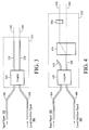
- Fig. 3 is an expanded view of the optical combining unit of Fig. 2 that includes two beams output from a coupler in accordance with the invention.
- Fig. 4 is an expanded view of the optical combining unit of Fig. 2 that includes one beam output from a coupler and split by a polarizing beam splitter in accordance with the invention.
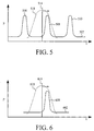
- Fig. 5 is a graph of an unfiltered input signal and a swept local oscillator signal in relation to the passband of an optical pre-selector that tracks the swept local oscillator signal.
- Fig. 6 is a graph of a filtered input signal and a swept local oscillator signal in relation to the passband of an optical pre-selector that tracks the swept local oscillator.
- Fig. 7 is a depiction of an optical heterodyne detection system that includes an optical combining unit, an optical pre-selector, and four photodetectors in accordance with the invention.
- Fig. 8 is an expanded view of the optical combining unit of Fig. 7 that includes two beams output from a coupler and split by a polarizing beam splitter in accordance with the invention.
- Fig. 9 is a depiction of an example optical pre-selector in relation to the optical combining unit and four photodetectors that is related to the systems depicted in Figs. 7 and 8 in accordance with the invention.
- Fig. 10 is a graphical depiction of the signal processing that is performed on the electrical signals that are generated from the system of Figs. 7 and 8 in accordance with the invention.
- Fig. 11A is a process flow diagram of a method for monitoring an input signal utilizing optical heterodyne detection that includes optical pre-selection.
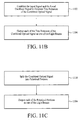
- Fig. 11B is a process flow diagram of process steps related to the process flow diagram of Fig. 11A.
- Fig. 11C is a process flow diagram of process steps related to the process flow diagram of Fig. 11A.
- Fig. 11D is a process flow diagram of process steps related to the process flow diagram of Fig. 11A.
- Fig. 12 is a process flow diagram of processing steps related to the process flow diagram of Fig. 11A.
- Fig. 13 is a depiction of an optical heterodyne detection system that includes two intensity noise reducers, a local oscillator amplifier, and an optical combining unit in accordance with the invention.
- Fig. 14 is a depiction of an optical heterodyne detection system that includes two intensity noise reducers, a local oscillator amplifier, an optical combining unit, and an optical pre-selector in accordance with the invention.
- Fig. 15A is a process flow diagram of a method for monitoring an input signal utilizing optical heterodyne detection that includes intensity noise reduction.
- Fig. 15B is a process flow diagram of a process step related to the process flow diagram of Fig. 12A.
- Fig. 15C is a process flow diagram of a process step related to the process flow diagram of Fig. 12A.
- Fig. 15D is a process flow diagram of a process step related to the process flow diagram of Fig. 12A.
- Fig. 16 is a depiction of an example intensity noise reducer that may be utilized with the systems of Figs. 13 and 14.
- Fig. 17 is a depiction of an example intensity noise reducer that may be utilized with the systems of Figs. 13 and 14.
- Fig. 18 is a graph of the power spectral density of an input signal vs. frequency after the intensity noise has been reduced by the intensity noise reducer of Fig. 17.
- An embodiment of the invention involves an optical heterodyne detection system in which an input signal and a swept local oscillator signal are combined and output as at least two beams.
- the at least two beams are filtered by a filter that passes a wavelength band that tracks the wavelength of the swept local oscillator signal.
- filtering of the at least two beams is adjusted to track the wavelength of the local oscillator signal. Filtering the beams to pass a wavelength band corresponding to the wavelength of the swept local oscillator signal reduces the intensity noise contributed from light sources having wavelengths that are not near the wavelength of the local oscillator signal.
- Fig. 2 depicts an optical heterodyne detection system that includes an input signal 202, a signal fiber 204, a local oscillator signal 206, a local oscillator fiber 208, an optical combining unit 210, an optical pre-selector 214, two photodetectors 212, and a processor 216. It should be noted that throughout the description similar element numbers are utilized to identify similar elements.
- the input signal 202 and the local oscillator signal 206 include optical signals that are generated from conventional devices as is known in the field of optical communications systems.
- the input signal and the local oscillator signal may be generated by lasers.
- the input signal may consist of a single wavelength or the input signal may include multiple wavelengths as is known in the field of wavelength division multiplexing (WDM).
- WDM wavelength division multiplexing
- the input signal may be an optical signal having unknown optical characteristics, in which case the optical heterodyne detection system can be utilized for optical spectrum analysis.
- the input signal may alternatively be a delayed portion of the local oscillator signal that is utilized for optical network analysis.
- the characteristics of a network or a single network component can be determined by inputting a known input signal into the network or the single network component and then measuring the response to the known signal.
- the local oscillator signal 206 is a widely tunable optical signal generated from a wideband tunable laser.
- the local oscillator signal may be tunable over a range of one nanometer or greater.
- the local oscillator signal is typically swept across a wavelength range in order to detect the input signal over a range of wavelengths.
- the signal fiber 204 carries the input signal 202 that is to be detected by the system.
- the signal fiber is a single mode optical fiber as is known in the art, although other optical waveguides may be utilized.
- waveguides are described, optical signals may be input into the system, or transmitted within the system, in free space.
- the local oscillator fiber 208 is an optical fiber, such as a single mode optical fiber, that carries the local oscillator signal 206.
- the local oscillator fiber may include a polarization controller (not shown) that controls the polarization state of the local oscillator signal.
- Other optical waveguides may be utilized in place of single mode optical fiber, such as polarization preserving fiber.
- the local oscillator signal may be transmitted through free space without the use of a waveguide.
- the optical combining unit 210 optically combines the input signal 202 and the local oscillator signal 206 into a combined optical signal and outputs at least two beams of the combined optical signal.
- the combined optical signal includes the heterodyne signal and intensity noise from the input signal and from the local oscillator signal.
- the input signal and the local oscillator signal are combined in a manner that ensures the spatial overlap of the input signal and the local oscillator signal, thereby allowing full interference between the input signal and the local oscillator signal.
- the optical combining unit includes a coupler that outputs the combined optical signal into two optical paths.
- the optical combining unit includes a coupler and a polarizing beam splitter that outputs two polarized portions of the combined optical signal.
- Fig. 3 is a depiction of an embodiment of the optical combining unit 210 in which the optical combining unit includes an optical coupler 320 that has two outputs represented by two output fibers 318 and 328.
- the optical combining unit includes an optical coupler 320 that has two outputs represented by two output fibers 318 and 328.
- two portions of the combined optical signal 340 and 342 are output from the two fibers.
- the two output portions of the combined optical signal are transmitted from the coupler to the optical pre-selector and then to the two corresponding photodetectors.
- the resulting output signal is not independent of the polarization state of the input signal.
- the power distribution of the input signal and local oscillator signal between the two output fibers is influenced by the optical coupler and can be controlled to accomplish the desired power distribution.
- the power of the combined optical signal is distributed approximately evenly between the two output fibers.
- the optical coupler 320 in Fig. 3 may be an optically directional 3dB fiber coupler, although other optical couplers may be utilized.
- the optical coupler is substantially independent of the polarization of optical signals.
- the optical coupler does not polarize the combined optical signal.
- Fig. 4 is a depiction of an embodiment of the optical combining unit 210 in which the optical combining unit includes an optical coupler 420, a polarizing beam splitter 424, and a half-wave plate 426.
- the optical coupler combines the input signal 402 and the local oscillator signal 406 onto at least one waveguide. As shown in Fig. 4, the optical coupler combines the input signal and the local oscillator signal and outputs the combined optical signal into output fiber 428. It should be noted that although output fiber 418 is shown, there may not be two outputs from the coupler 420.
- the length of the output fiber 428 is chosen to provide sufficient attenuation of any cladding modes before the light of the input signal or the local oscillator signal reaches the end of the output fiber.
- the length of the output fiber should be chosen such that cladding mode light accounts for less than one percent of the total light emitted from the output fiber.
- the polarizing beam splitter 424 separates an incoming optical beam into two polarized beams so that an output signal that is independent of the polarization state of the input signal can be generated.
- the polarizing beam splitter may include, for example, a birefringent crystal that provides polarization walk-off, such as a rutile walk-off crystal.
- the polarizing beam splitter separates the combined optical signal beam into two beams having different polarization states.
- the polarizing beam splitter separates the incoming beam into two linearly polarized components that have orthogonal directions of polarization.
- the polarization of the local oscillator signal is controlled such that the power contributed from the local oscillator signal is split approximately evenly by the polarizing beam splitter.
- the optical coupler 420 and the polarizing beam splitter are shown as physically separate devices connected by optical fiber 428, the optical coupler and polarizing beam splitter may be integrated into a planar waveguide circuit that does not require optical fiber connections. It should be understood that other polarizing beam splitters may be utilized.
- Fig. 4 shows how the beam of the combined optical signal carried on output fiber 428 is split into two differently polarized beams, as identified by the dashed lines 440 and 442.
- the straight line beam 440 follows an "ordinary” path and is referred to as the ordinary beam.
- the diagonal line beam 442 walks off in an "extraordinary” path and is referred to as the extraordinary beam.
- the two polarized beams 440 and 442 have the same polarization state before the beams enter the optical pre-selector.
- the polarization state of the extraordinary beam 442 is rotated to match the polarization state of the ordinary beam 440.
- the extraordinary beam is rotated by 90 degrees.
- a half-wave plate 426 is utilized to accomplish the 90-degree rotation.
- the optical pre-selector 214 is a tunable bandpass filter that is tuned to track the swept local oscillator signal 206. That is, the optical pre-selector is tuned so that the optical pre-selector has the highest optical transmission over a wavelength band that corresponds to the wavelength of the swept local oscillator signal.
- the optical pre-selector is located between the optical combining unit 210 and the two photodetectors 212.
- Fig. 5 depicts an input signal 502 as three optical carriers 506, 508, and 510 in a WDM system in relation to a swept local oscillator signal 514 before the combined input signal and swept local oscillator signal have entered the optical pre-selector.
- the dashed line 518 represents the passband of the optical pre-selector that is tuned to track the sweep of the local oscillator signals. Optical signals within the passband continue to be transmitted and optical signals outside of the passband are filtered by the optical pre-selector.
- Fig. 6 depicts the one optical carrier 608 that exits the optical pre-selector after the optical signals have been filtered.
- the optical pre-selector filters out optical carriers that are not near the wavelength of the swept local oscillator signal 614 (i.e., outside the passband of the optical pre-selector).
- the optical carriers that are not near the wavelength of the swept local oscillator signal are not necessary for optical heterodyne detection and only contribute to noise in the detection system if not filtered.
- Optical bandpass filtering that tracks the wavelength of the swept local oscillator signal is especially useful when measuring broadband optical noise, such as amplified spontaneous emissions from an optical amplifier.
- Tunable optical pre-selectors such as those described with reference to Figs. 2, 5, and 6 are well known in the field of optical communications and can be implemented utilizing components such as diffraction gratings, dielectric interference filters, Fabry-Perot interferometers, and other known interferometers.
- the embodiment of Fig. 2 has the optical pre-selector 214 located between the optical combining unit 210 and the photodetectors 212 because the polarization states of the beams can be directly controlled to provide beams with known polarization states. Reliable bandpass filtering techniques can be utilized to filter beams having known polarization states.
- the optical pre-selector can be placed in other locations, such a location along the optical path of the swept local oscillator signal that is before the optical combining unit, a location along the optical path of the input signal that is before the optical combining unit, or both locations.
- the two photodetectors 212 are aligned to separately detect the two filtered beams that are output from the optical pre-selector 214.
- the two photodetectors generate electrical signals in response to a corresponding one of the two filtered beams.
- the electrical signals generated by each of the two photodetectors are individually provided to the processor 216.
- the two connections between the photodetectors and the processor are depicted in Fig. 2 by two lines 252.
- the two photodetectors are depicted as two independent photodetectors, the two photodetectors may be combined into a single unit.
- the photodetectors may include additional circuitry such as signal amplifiers and filters, as is known in the field.
- the processor 216 receives the electrical signals from the two photodetectors 212 and processes the electrical signals into useful data.
- the processor may include analog signal processing circuitry and/or digital signal processing circuitry as is known in the field of electrical signal processing.
- analog signals from the photodetectors are converted into digital signals and the digital signals are subsequently processed. It should be understood that digital signal processing involves converting the electrical signals from the photodetectors into digital signals that are representative of the original electrical signals.
- Operation of the optical heterodyne detection system described with reference to Figs. 2 and 3 involves combining an input signal and a swept local oscillator signal into a combined optical signal and outputting two beams of the combined optical signal to the optical pre-selector 214.
- the two beams are then filtered by the optical pre-selector 214.
- the optical pre-selector passes a wavelength band that tracks the swept local oscillator signal.
- the two filtered beams are then detected by the two photodetectors 212.
- the two photodetectors generate electrical signals in proportion to the intensity of the optical beams that are detected.
- the electrical signals generated by the two photodetectors are then received by the processor 216 and processed in a manner that maximizes the signal to noise ratio of the heterodyne term of the combined optical signal.
- Processing of the electrical signals may involve providing intensity noise suppression.
- the center wavelength of the optical pre-selector passband tracks, in real-time, the wavelength of the swept local oscillator signal.
- the system may require an initial calibration operation in order to provide accurate results.
- Operation of the optical heterodyne detection system described with reference to Figs. 2 and 4 involves combining an input signal and a swept local oscillator signal into a combined optical signal, outputting one beam from the optical coupler, and then splitting the beam that is output from the optical coupler into two polarized beams.
- the combined optical signal that is output from the optical coupler is split into two polarized beams having different polarization states.
- the polarization state of the extraordinary portion of the split beam is then rotated so that the two polarized beams have the same polarization state.
- the two beams are then filtered by the optical pre-selector 214.
- the optical pre-selector passes a wavelength band that tracks the swept local oscillator signal.
- the two polarized and filtered beams are then detected by the two photodetectors 212.
- the two photodetectors generate electrical signals in proportion to the intensity of the optical beams that are detected.
- the electrical signals generated by the two photodetectors are then received by the processor 216 and processed in a manner that maximizes the signal to noise ratio of the heterodyne term of the combined optical signal. Processing of the electrical signals may involve squaring the electrical signals from the two photodetectors and then adding the two squared terms to generate an output signal that is independent of the polarization state of the input signal.
- the center wavelength of the optical pre-selector passband tracks, in real-time, the wavelength of the swept local oscillator signal.
- the optical combining unit includes a polarizing beam splitter
- the combination of the optical combining unit, the optical pre-selector, and the photodetectors creates an optical heterodyne detection system that filters the optical signals to reduce noise and improve the dynamic range of the system.
- the optical heterodyne detection system of Fig. 2 may include more than two beams being output from the optical combining unit 210.
- Fig. 7 is a depiction of an optical heterodyne detection system that includes four beams being output from the optical combining unit.
- Fig. 8 is an expanded view of an embodiment of an optical combining unit that outputs four polarized beams.
- the optical combining unit of Fig. 8 includes an optical coupler 820, two output fibers 818 and 828, a polarizing beam splitter 824, and two half-wave plates 826.
- the optical coupler combines the input signal and the local oscillator signal and distributes the combined optical signal into the two output fibers 818 and 828.
- the two output fibers carry the combined optical signal to the polarizing beam splitter 824.
- the power of the combined optical signal is distributed approximately evenly between the two output fibers.
- the optical coupler 820 may be an optically directional 3dB fiber coupler, although other optical couplers may be utilized.
- the optical coupler is substantially independent of the polarization of optical signals.
- the optical coupler does not polarize the combined optical signal.
- the polarizing beam splitter 824 splits each of the combined optical signal beams from the output fibers 818 and 828 into two beams having different polarization states.
- the polarizing beam splitter splits each of the incoming beams into two linearly polarized components that have orthogonal directions of polarization.
- the polarization of the local oscillator signal is controlled such that the power contributed from the local oscillator signal is split approximately evenly by the polarizing beam splitter.
- the polarizing beam splitter is described as a single device, the polarizing beam splitter may include multiple beam splitters in configurations that accomplish the task of splitting the incoming beams based on beam polarization.
- Fig. 8 shows how the two beams of the combined optical signal are each split into two differently polarized beams, as identified by the dashed lines 840, 842, 844, and 846.
- the straight line beams 840 and 844 follow an "ordinary" path and are referred to as the ordinary beams.
- the diagonal line beams 842 and 846 walk off in an "extraordinary” path and are referred to as the extraordinary beams.
- each of the four polarized beams 840, 842, 844, and 846 have the same polarization state before the beams enter the optical pre-selector.
- the polarization states of the two extraordinary beams 842 and 846 are rotated to match the polarization state of the two ordinary beams.
- two half-wave plates 826 are utilized to accomplish a 90-degree rotation.
- Fig. 8 represents one arrangement for generating four beams with the same polarization state, other arrangements may alternatively be utilized within the optical combining unit 710 as would be apparent to one of ordinary skill in the field of optical communications systems.
- the optical pre-selector 714 includes a tunable bandpass filter that is tuned to track the swept local oscillator signal 706.
- An embodiment of an optical pre-selector that includes a tunable diffraction grating is described in detail with reference to Fig. 9. As shown in Fig. 9, four beams having the same polarization state exit the optical combining unit 910 and contact the tunable diffraction grating 914.
- the tunable diffraction grating is tuned to pass a wavelength band that tracks the wavelength of the swept local oscillator signal 906. In an embodiment, the diffraction grating is tuned by adjusting the angle of the diffraction grating.
- the filtered beams that reflect off of the diffraction grating are directed to the four photodetectors 912 for optical detection.
- a tunable diffraction grating may be utilized in the same fashion in embodiments that include only two beams and two photodetectors.
- the four photodetectors 712 are aligned to separately detect the four polarized and filtered beams that are output from the optical pre-selector 714. Each of the four photodetectors generates an electrical signal in response to a corresponding one of the four polarized and filtered beams. The electrical signal generated by each of the four photodetectors is individually provided to the processor 716. The processor 716 receives the electrical signals from the four photodetectors 712 and processes the electrical signals into useful data.
- Operation of the optical heterodyne detection system described with reference to Figs. 7 and 8 involves combining an input signal and a swept local oscillator signal into a combined optical signal and outputting two beams of the combined optical signal from the optical coupler.
- Each of the two beams containing the combined optical signal is then split into two polarized beams having different polarization states.
- the polarization states of the extraordinary portions of the split beams are then rotated so that all four beams have the same polarization state.
- the four beams are then filtered by the optical pre-selector 714.
- the optical pre-selector passes a wavelength band that tracks the wavelength of the swept local oscillator signal.
- the passband of the optical pre-selector is tuned in real-time to track the wavelength of the local oscillator signal.
- the four polarized and filtered beams are then detected by the four photodetectors 712.
- the four photodetectors generate electrical signals in proportion to the intensity of the optical beams that are detected.
- the electrical signals generated by the four photodetectors are then received by the processor 716 and processed in a manner that maximizes the signal to noise ratio of the heterodyne term of the combined optical signal. Processing of the electrical signals may involve providing intensity noise suppression and polarization independence.
- Fig. 10 is an example graphical depiction of how the electrical signals generated by a system with four photodetectors are processed to achieve intensity noise suppression and polarization diversity.
- the signal processing preferably involves digital signal processing although this is not critical.
- the photodetectors 1044 and 1046 are partially identified by "1," which corresponds to the beam (beam 1) that is output from the first output fiber 818 of the optical coupler 820 as shown in Fig. 8.
- the photodetectors 1048 and 1050 are partially identified by the number "2,” which corresponds to the beam (beam 2) that is output from the second output fiber 828 of the optical coupler shown in Fig. 8.
- the two photodetectors 1046 and 1050 that receive the ordinary portions of the split beams are partially identified by the letter “o,” which corresponds to the ordinary beams exiting from the optical combining unit.
- the two photodetectors 1044 and 1048 that receive the extraordinary portions of the split beams are partially identified by the letter “e,” which corresponds to the extraordinary beams exiting from the optical combining unit.
- the four beams, the respective photodetectors, and the respective electrical signals are identified as "1e,” “1o,” “2e,” and "2o.” It should be noted that although the beams are identified as extraordinary and ordinary, in an embodiment, the polarization states of all four beams have been made the same.
- signal subtractions are performed between the "1o” signal and the “2o” signal, and between the "1e” signal and the “2e” signal.
- the subtraction functions are represented by subtraction units 1054 and 1056, respectively.
- the subtraction functions are performed to provide intensity noise suppression by canceling out the intensity noise components of the optical signals that are received by each photodetector.
- the subtraction functions cancel out the intensity noise because the intensity noise is common to each signal. That is, the amplitudes of the "1e” and “2e” signals fluctuate synchronously and by the same percentage relative to each other, and the "1o” and “2o” signals fluctuate synchronously and by the same percentage relative to each other. In the embodiment of Fig. 4 where only one beam is split into two polarized beams, the subtraction functions are not performed.
- the electrical signals generated from the ordinary beam portions include a cos ⁇ term and the electrical signals generated from the extraordinary beam portions include a sin ⁇ term.
- the cos ⁇ term is squared, as represented by squaring unit 1058, and the sin ⁇ term is squared, as represented by squaring unit 1060.
- the squaring units generate output signals that are proportional to the square of the input signals.
- the output signals from the squaring units are each connected to low pass filtering units 1064 and 1068 although the low pass filtering units may not be critical.
- the low pass filtering units provide low pass filtering on the squared output signals.
- the output signals from the low pass filtering units are each connected to an input terminal of an adder unit, designated 1070, which produces a readout signal that is proportional to the sum of the signals from the low pass filtering units. Squaring the cos ⁇ term and the sin ⁇ term, low pass filtering the terms, and then adding the squared and filtered cos ⁇ term to the squared and filtered sin ⁇ term provides a result that is independent of the angle of polarization ( ⁇ ) of the input signal and therefore polarization diverse.
- the subtraction function is performed to electronically reduce the intensity noise, however the squaring and adding functions are not used.
- the squaring and adding functions are performed to provide a result that is independent of the angle of polarization of the input signal, however the subtraction function is not used. It should be understood that in a digital system the subtracting, squaring, low pass filtering, and adding units may be incorporated into a multi-function processor.
- the combination of the optical combining unit 710, the optical pre-selector 714, the four photodetectors 712, the processor 716, including units 1054, 1056, 1058, 1060, 1064, 1068, and 1070 creates a system that filters optical signals to reduce noise, that is insensitive to the polarization state of the input signal, and that suppresses the intensity noise of the split beams that are detected by the four photodetectors.
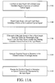
- a method for monitoring an optical signal utilizing an optical heterodyne detection system with optical pre-selection is described herein and depicted in the process flow diagram of Fig. 11A.
- a step 1102 an input signal is combined with a swept local oscillator signal to generate a combined optical signal.
- a step 1104 light beams are output with each light beam including a portion of the combined optical signal.
- each of the light beams is filtered to pass a wavelength band that tracks the wavelength of the swept local oscillator signal, wherein the filtering generates filtered portions of the light beams.
- electrical signals are generated in response to the filtered portions of the light beams.
- the electrical signals are processed to determine an optical characteristic represented by the input signal.
- An embodiment of the method depicted in Fig. 11A includes details of steps 1102 and 1104.
- step 1102 the input signal and the swept local oscillator signal are combined to generate two instances of the combined optical signal and in step 1104 each of the two instances of the combined optical signal is output as one of the light beams.
- step 1118 the combined optical signal is split into polarized portions and in step 1104 each of the polarized portions is output as one of the light beams.
- step 1102 the input signal and the swept local oscillator signal are combined to generate two instances of the combined optical signal.
- step 1126 the two instances of the combined optical signal are split into two polarized portions.
- each of the four polarized portions is output as one of the light beams.
- the first, second, third, and fourth polarized portions are filtered to pass a wavelength band that tracks the wavelength of the swept local oscillator signal.
- step 1108 first, second, third, and fourth electrical signals are generated in response to the filtered portions of the first, second, third, and fourth light beams.
- the first, second, third, and fourth electrical signals are processed to determine an optical characteristic represented by the input signal.
- a step 1202 the processing involves subtracting the first electrical signal from the third electrical signal in order to suppress intensity noise, thereby creating a first subtracted signal, and subtracting the second electrical signal from the fourth electrical signal in order to suppress intensity noise, thereby creating a second subtracted signal. It should be noted that these process steps are not utilized when the combined optical signal is split into only two polarized beams.
- the processing further involves squaring the first subtracted signal, thereby creating a first squared signal, and squaring the second subtracted signal, thereby creating a second squared signal.
- the processing further involves adding the first squared signal to the second squared signal in order to achieve polarization independence.
- the processing further involves low pass filtering the first squared signal before the step of adding and low pass filtering the second squared signal before the step of adding.
- the filtering of the beams is adjusted in real-time to track the wavelength change of the swept local oscillator signal.
- the intensity noise of the input signal is reduced before the input signal is combined with the swept local oscillator signal.
- the intensity noise of the swept local oscillator signal is reduced before the swept local oscillator signal is combined with the input signal.
- the swept local oscillator signal is amplified before the intensity noise of the swept local oscillator signal is reduced.
- An embodiment of an optical heterodyne detection system may include a switch associated with the signal fiber.
- the switch is utilized to selectively block transmission of the input signal in order to calibrate the system.
- the coupling coefficient of the optical combing unit can be determined as a function of wavelength by sweeping the local oscillator signal across a range of wavelengths.
- the responsivity of the photodetectors can be determined as a function of wavelength by sweeping the local oscillator signal while the input signal is switched off.
- the distribution of the local oscillator signal onto the photodetectors can be determined as a function of wavelength by sweeping the local oscillator signal while the input signal is switched off. It is preferable that the local oscillator signal is approximately evenly distributed among the photodetectors. If the local oscillator signal is not evenly distributed among the photodetectors, then the power distribution of the local oscillator signal may be adjusted utilizing a polarization controller.
- FIG. 13 Another embodiment of the invention involves an optical heterodyne detection system in which the intensity noise of the input signal and/or the intensity noise of the swept local oscillator signal is reduced before the input signal and the swept local oscillator signal are combined.
- An embodiment of the optical heterodyne detection system is depicted in Fig. 13 and includes an input signal 1302, a signal fiber 1304, an intensity noise reducer 1376 on the signal fiber, a local oscillator signal 1306, a local oscillator fiber 1308, an optical amplifier 1380 and an intensity noise reducer 1378 on the local oscillator fiber, an optical combining unit 1310, two photodetectors 1312, and a processor 1316.
- FIG. 13 does not include an optical pre-selector as described with reference to the system of Fig. 2. Elements shown in Fig. 13 that are similar to elements shown in Fig. 2 are identified by similar element numbers. In addition, the above-provided descriptions apply to similar elements in Fig. 13. Operation of the optical heterodyne detection system of Fig. 13 is also similar to the system of Fig. 2 except that there is no optical pre-selection.
- Fig. 13 includes the two intensity noise reducers 1376 and 1378 and the optical amplifier 1380 on the same system
- other embodiments of the optical heterodyne detection system may include any combination of the intensity noise reducers and the optical amplifier.
- an embodiment of the system may include the intensity noise reducer 1376 on the signal fiber 1304 and no intensity noise reducer on the local oscillator fiber 1308.
- an embodiment may include the intensity noise reducer 1378 on the local oscillator fiber and no intensity noise reducer on the signal fiber.
- the intensity noise reducers are located before the optical combining unit 1310, the intensity noise reducers may be placed in other locations within the optical heterodyne detection system.
- intensity noise reducers 1376 and 1378 on the input fiber 1304 and/or the local oscillator fiber 1308 reduces the intensity noise that is detected by the photodetectors 1312 and improves the signal to noise ratio and the dynamic range of the heterodyne detection system.
- Optical intensity noise reduction can be accomplished utilizing various techniques. Example intensity noise reduction systems are described below with reference to Fig. 16 - 18.
- the optical amplifier 1380 on the local oscillator fiber 1308 is utilized to increase the power of the local oscillator signal 1306, thereby improving the signal to noise ratio and dynamic range of the heterodyne detection system.
- An erbium doped fiber amplifier may be utilized to amplify the local oscillator signal.
- the intensity noise reducer 1378 on the local oscillator fiber should be utilized when the optical amplifier is utilized in order to control the additional intensity noise that is contributed by the optical amplifier.
- Fig. 13 While the embodiment of Fig. 13 includes intensity noise reduction for the input signal 1302 and/or the local oscillator signal 1306, it does not include the optical pre-selector as described above with regard to the optical heterodyne detection system of Fig. 2.
- An optical pre-selector can be added to the system of Fig. 13 to create the system that is depicted in Fig. 14.
- the system depicted in Fig. 14 includes an intensity noise reducer 1476 on the input fiber 1404, an intensity noise reducer 1478 and an optical amplifier 1480 on the local oscillator fiber 1408, and an optical pre-selector 1414 located between the optical combining unit 1410 and the photodetectors 1412.
- the system of Fig. 14 operates similarly to the systems described with reference to Figs. 2 and 13.
- Fig. 14 includes an optical combining unit and two photodetectors, the system may alternatively include more than two beams exiting the optical combining unit along with corresponding photodetectors.
- the two intensity noise reducers 1476 and 1478 and the optical amplifier 1480 shown in Fig. 14 are depicted as parts of the same system, it should be understood that any combination of the intensity noise reducers and the optical amplifier may be implemented in a particular system.
- an embodiment may include only an intensity noise reducer on the input fiber, or only an intensity noise reducer on the local oscillator fiber, or the intensity noise reducer and the optical amplifier on the local oscillator fiber and no intensity noise reducer on the input fiber.
- the intensity noise reducers are located before the optical combining unit 1410, the intensity noise reducers may be placed in other locations within the optical heterodyne detection system.
- Utilizing intensity noise reducers 1476 and 1478 on the input fiber 1404 and/or the local oscillator fiber 1408 in conjunction with the optical pre-selector 1414 reduces the intensity noise that is detected by the photodetectors 1412 and improves the signal to noise ratio and the dynamic range of the heterodyne detection system.
- a method for monitoring an optical signal utilizing an optical heterodyne detection system with intensity noise reduction is depicted in the process flow diagram of Fig. 15A.
- the intensity noise of a first signal is reduced.
- the noise reduced first signal is combined with a second signal to generate a combined optical signal.
- One of the first and second signals is a swept local oscillator signal and the other signal is an input signal.
- light beams are output, wherein the light beams each include a portion of the combined optical signal.
- electrical signals are generated in response to the light beams.
- the electrical signals are processed to determine an optical characteristic represented by the input signal.
- An embodiment of the method depicted in Fig. 15A includes an additional step 1514 of reducing the intensity noise of the second signal before the second signal is combined with the reduced first signal as shown in Fig. 15B.
- An embodiment of the method depicted in Fig. 15A includes an additional step 1516 of amplifying the first signal before the intensity noise of the first signal is reduced as shown in Fig. 15C.
- An embodiment of the method depicted in Fig. 15A includes an additional step 1518 of filtering the light beams before the electrical signals are generated as shown in Fig. 15D.
- An embodiment of the method depicted in Fig. 15A includes details of steps 1504 and 1506. Referring back to Fig. 11B, in step 1114 the input signal and the swept local oscillator signal are combined to generate two instances of the combined optical signal and in step 1116 each of the two instances of the combined optical signal is output as one of the light beams.
- step 1118 the combined optical signal is split into polarized portions and in step 1104 each of the polarized portions is output as one of the light beams.
- FIG. 15A Another embodiment of the method depicted in Fig. 15A includes details of steps 1504 and 1506 and an additional step that are the same as the process steps provided in Fig. 11D except that the polarized light beams are not filtered as recited in step 1106.
- the above-provided description of the steps in Fig. 11D relates to the process of Fig. 15A and is therefore not repeated.
- Fig. 12 Details of the processing recited in step 1510 of Fig. 15A are represented in Fig. 12. The above-provided description of the steps in Fig. 12 relates to the process of Fig. 15A and is therefore not repeated.
- intensity noise reducer 1684 of Fig. 16 can be utilized on the signal fiber and/or the local oscillator fiber 1686.
- the intensity noise reducer is included in the local oscillator fiber 1686 and the system includes a coupler 1688, a photodetector 1690, a feedback system 1692, and an amplitude modulator 1694.
- Intensity noise is reduced by sampling the incoming signal to measure the intensity noise and then amplitude modulating the incoming signal to smooth out the intensity noise.
- the amplitude modulator may include a LiNbO 3 modulator, an acousto-optic modulator, an optical semiconductor amplifier, or any other device that can change the transmission of the incoming signal in response to a feedback signal.
- the intensity noise reducer 1784 of Fig. 17 can be utilized on the signal fiber and/or the local oscillator fiber 1786.
- the intensity noise reducer is included in the local oscillator fiber 1786 and the system includes an input fiber 1788, an output fiber 1790, a first delay fiber 1791, a second delay fiber 1792, a coupler 1793, a delay unit 1794, a Faraday mirror 1795, a half-wave plate rotated at 45 degrees 1796, and an ordinary mirror 1797.
- the input fiber is polarization maintaining fiber and the incoming signal (either the input signal or the local oscillator signal) is at zero degrees relative to the polarization maintaining fiber.
- the Faraday mirror on the first delay fiber and the half-waveplate and mirror on the second delay fiber create two delayed signals that have orthogonal polarizations.
- the intensity noise fluctuations within a predetermined frequency range are combined with 180 degrees of phase difference. Because the intensity noise fluctuations are 180 degrees out of phase, the intensity noise of the two delayed signals cancel out and the resulting signal on the output fiber has reduced intensity noise.
- the above-described intensity noise reduction technique can be implemented with other arrangements utilizing, for example, regular beam splitters, standard single mode fiber directional couplers, and Faraday mirrors.
- Fig. 18 is a graph of the power spectral density of an input signal vs. frequency after the intensity noise has been reduced utilizing the intensity noise reducer as utilized in Fig. 17.
- the solid line 1890 represents the filtered intensity noise and the dashed line 1892 represents the location of the heterodyne signal relative to the filtered intensity noise.
Landscapes
- Physics & Mathematics (AREA)
- Electromagnetism (AREA)
- Engineering & Computer Science (AREA)
- Computer Networks & Wireless Communication (AREA)
- Signal Processing (AREA)
- Optical Communication System (AREA)
- Light Receiving Elements (AREA)
Applications Claiming Priority (2)
| Application Number | Priority Date | Filing Date | Title |
|---|---|---|---|
| US09/506,196 US6259529B1 (en) | 2000-02-17 | 2000-02-17 | Wavelength-selective polarization-diverse optical heterodyne receiver |
| US506196 | 2000-02-17 |
Publications (2)
| Publication Number | Publication Date |
|---|---|
| EP1130815A2 true EP1130815A2 (fr) | 2001-09-05 |
| EP1130815A3 EP1130815A3 (fr) | 2004-09-22 |
Family
ID=24013588
Family Applications (1)
| Application Number | Title | Priority Date | Filing Date |
|---|---|---|---|
| EP00123257A Withdrawn EP1130815A3 (fr) | 2000-02-17 | 2000-10-26 | Récepteur hétérodyne optique en diversité de polarisation et sélectif en longeur d'onde |
Country Status (3)
| Country | Link |
|---|---|
| US (1) | US6259529B1 (fr) |
| EP (1) | EP1130815A3 (fr) |
| JP (1) | JP2001281104A (fr) |
Cited By (2)
| Publication number | Priority date | Publication date | Assignee | Title |
|---|---|---|---|---|
| US6535289B1 (en) | 2000-06-02 | 2003-03-18 | Agilent Technologies, Inc. | System and method for optical heterodyne detection of an optical signal |
| WO2011019683A1 (fr) * | 2009-08-14 | 2011-02-17 | Alcatel-Lucent Usa Inc. | Récepteur cohérent comportant un réseau de guides d'ondes à compression et entrelacement |
Families Citing this family (19)
| Publication number | Priority date | Publication date | Assignee | Title |
|---|---|---|---|---|
| US6614955B1 (en) * | 2000-08-22 | 2003-09-02 | Agilent Technologies, Inc. | Method and apparatus for an extended wavelength range coherent optical spectrum analyzer |
| US6856400B1 (en) * | 2000-12-14 | 2005-02-15 | Luna Technologies | Apparatus and method for the complete characterization of optical devices including loss, birefringence and dispersion effects |
| US6515276B2 (en) * | 2001-03-17 | 2003-02-04 | Agilent Technologies, Inc. | Heterodyne optical spectrum analyzer with provisions for intensity noise subtraction |
| US7088877B2 (en) * | 2001-06-13 | 2006-08-08 | Intel Corporation | Method and apparatus for tuning a bragg grating in a semiconductor substrate |
| US20030016425A1 (en) * | 2001-07-19 | 2003-01-23 | Tan Tun Sein | Polarization diversity receiver with planar waveguide and polarizing beam splitter |
| US6950577B2 (en) * | 2002-07-01 | 2005-09-27 | Intel Corporation | Waveguide-based Bragg gratings with spectral sidelobe suppression and method thereof |
| US6813028B2 (en) * | 2002-07-25 | 2004-11-02 | Agilent Technologies, Inc. | Calibration methodology and system for optical network analyzer |
| US7245792B2 (en) * | 2002-08-16 | 2007-07-17 | Intel Corporation | Silicon-based tunable single passband optical filter |
| US20040088274A1 (en) * | 2002-10-31 | 2004-05-06 | Zhichen Xu | Semantic hashing |
| US7330669B2 (en) * | 2004-04-20 | 2008-02-12 | Lucent Technologies Inc. | Optical heterodyne receiver based on oversampling |
| US7466425B2 (en) * | 2005-04-22 | 2008-12-16 | Agilent Technologies, Inc. | Elementary matrix based optical signal/network analyzer |
| US8045861B1 (en) * | 2006-11-17 | 2011-10-25 | Hrl Laboratories, Llc | Method and system for spectral suppression of noise in a communication signal |
| US20100054761A1 (en) * | 2008-08-28 | 2010-03-04 | Young-Kai Chen | Monolithic coherent optical detectors |
| US20100158521A1 (en) * | 2008-12-18 | 2010-06-24 | Alcatel-Lucent Usa Inc. | Optical mixer for coherent detection of polarization-multiplexed signals |
| MY167202A (en) | 2009-03-20 | 2018-08-13 | Alcatel Lucent | Coherent optical detector having a multifunctional waveguide grating |
| JP5492118B2 (ja) * | 2011-02-21 | 2014-05-14 | 日本電信電話株式会社 | Wdm信号一括コヒーレント受信器及び方法 |
| JP5699769B2 (ja) * | 2011-04-13 | 2015-04-15 | 富士通株式会社 | 光チャンネルモニタおよび光伝送装置 |
| JP2017195482A (ja) * | 2016-04-19 | 2017-10-26 | 富士通株式会社 | 光伝送システム、伝送装置および波長制御方法 |
| JP7408965B2 (ja) * | 2019-09-11 | 2024-01-09 | 住友電気工業株式会社 | 光モジュール |
Family Cites Families (6)
| Publication number | Priority date | Publication date | Assignee | Title |
|---|---|---|---|---|
| US4856899A (en) | 1985-12-20 | 1989-08-15 | Yokogawa Electric Corporation | Optical frequency analyzer using a local oscillator heterodyne detection of incident light |
| DE3621734A1 (de) * | 1986-06-28 | 1988-01-07 | Standard Elektrik Lorenz Ag | Optischer ueberlagerungsempfaenger |
| NL8602864A (nl) * | 1986-11-12 | 1988-06-01 | Philips Nv | Inrichting voor optische heterodyne detektie van een optische signaalbundel en optisch transmissiesysteem voorzien van een dergelijke inrichting. |
| US5060312A (en) * | 1990-03-05 | 1991-10-22 | At&T Bell Laboratories | Polarization independent coherent lightwave detection arrangement |
| GB9027276D0 (en) * | 1990-12-17 | 1991-02-06 | Philips Nv | Coherent optical multichannel receiver |
| DE4244605A1 (de) | 1992-05-27 | 1993-12-02 | Hewlett Packard Co | Optisches Niederkohärenzreflektometer von verbesserter Empfindlichkeit mit optischer Dämpfung |
-
2000
- 2000-02-17 US US09/506,196 patent/US6259529B1/en not_active Expired - Fee Related
- 2000-10-26 EP EP00123257A patent/EP1130815A3/fr not_active Withdrawn
-
2001
- 2001-02-19 JP JP2001042336A patent/JP2001281104A/ja active Pending
Non-Patent Citations (1)
| Title |
|---|
| None * |
Cited By (5)
| Publication number | Priority date | Publication date | Assignee | Title |
|---|---|---|---|---|
| US6535289B1 (en) | 2000-06-02 | 2003-03-18 | Agilent Technologies, Inc. | System and method for optical heterodyne detection of an optical signal |
| WO2011019683A1 (fr) * | 2009-08-14 | 2011-02-17 | Alcatel-Lucent Usa Inc. | Récepteur cohérent comportant un réseau de guides d'ondes à compression et entrelacement |
| CN102598548A (zh) * | 2009-08-14 | 2012-07-18 | 阿尔卡特朗讯 | 具有交错啁啾阵列波导光栅的相干接收器 |
| US8275224B2 (en) | 2009-08-14 | 2012-09-25 | Alcatel Lucent | Coherent receiver having an interleave-chirped arrayed waveguide grating |
| CN102598548B (zh) * | 2009-08-14 | 2015-02-11 | 阿尔卡特朗讯 | 具有交错啁啾阵列波导光栅的相干接收器 |
Also Published As
| Publication number | Publication date |
|---|---|
| JP2001281104A (ja) | 2001-10-10 |
| US6259529B1 (en) | 2001-07-10 |
| EP1130815A3 (fr) | 2004-09-22 |
Similar Documents
| Publication | Publication Date | Title |
|---|---|---|
| US6259529B1 (en) | Wavelength-selective polarization-diverse optical heterodyne receiver | |
| US6256103B1 (en) | System and method for optical heterodyne detection of an optical signal | |
| US7027743B1 (en) | System and method for optical heterodyne detection of an optical signal including optical pre-selection that is adjusted to accurately track a local oscillator signal | |
| EP1278087B1 (fr) | Recepteur pour la detection d'etats de polarisation differents avec guides d'ondes planaire et séparateur de faisceaux polarisant | |
| EP1253730B1 (fr) | Procédé et système pour analyse spectrale optique et détection utilisant un filtre apparié | |
| US6671056B2 (en) | Method and system for optical spectrum analysis with a depolarized local oscillator signal | |
| US6590666B2 (en) | Method and system for optical spectrum analysis with non-uniform sweep rate correction | |
| EP1130814B1 (fr) | Système et méthode de détection hétérodyne d'un signal optique | |
| US6535289B1 (en) | System and method for optical heterodyne detection of an optical signal | |
| JP2004147323A (ja) | 制御された光減衰を用いるヘテロダインベースの光スペクトル分析 | |
| US7095963B2 (en) | Multi-channel optical receiver for processing tri-cell polarization diversity detector outputs | |
| US6977720B2 (en) | Characterization of active and passive optical properties of an optical device | |
| EP1130813B1 (fr) | Méthode et système de détection hétérodyne optique utilisant l'atténuation optique | |
| JP2003526794A (ja) | オプトエレクトロニクス伝送ラインのpmdを検出する装置 | |
| JP2004350081A (ja) | ノイズ抑圧方法及び装置 | |
| US6646746B1 (en) | Method and system for optical heterodyne detection of an optical signal | |
| CN112104415A (zh) | 一种采用edfa放大装置检测瑞利散射信号强度的系统 | |
| JP3403643B2 (ja) | 偏波依存性精密測定機器 | |
| JPH10176976A (ja) | 分岐光線路の損失分布測定装置および損失分布の測定方法 |
Legal Events
| Date | Code | Title | Description |
|---|---|---|---|
| PUAI | Public reference made under article 153(3) epc to a published international application that has entered the european phase |
Free format text: ORIGINAL CODE: 0009012 |
|
| AK | Designated contracting states |
Kind code of ref document: A2 Designated state(s): AT BE CH CY DE DK ES FI FR GB GR IE IT LI LU MC NL PT SE |
|
| AX | Request for extension of the european patent |
Free format text: AL;LT;LV;MK;RO;SI |
|
| RAP1 | Party data changed (applicant data changed or rights of an application transferred) |
Owner name: AGILENT TECHNOLOGIES, INC. (A DELAWARE CORPORATION |
|
| PUAL | Search report despatched |
Free format text: ORIGINAL CODE: 0009013 |
|
| AK | Designated contracting states |
Kind code of ref document: A3 Designated state(s): AT BE CH CY DE DK ES FI FR GB GR IE IT LI LU MC NL PT SE |
|
| AX | Request for extension of the european patent |
Extension state: AL LT LV MK RO SI |
|
| 17P | Request for examination filed |
Effective date: 20050223 |
|
| AKX | Designation fees paid |
Designated state(s): DE FR GB |
|
| RAP1 | Party data changed (applicant data changed or rights of an application transferred) |
Owner name: AGILENT TECHNOLOGIES, INC. |
|
| GRAP | Despatch of communication of intention to grant a patent |
Free format text: ORIGINAL CODE: EPIDOSNIGR1 |
|
| STAA | Information on the status of an ep patent application or granted ep patent |
Free format text: STATUS: THE APPLICATION IS DEEMED TO BE WITHDRAWN |
|
| 18D | Application deemed to be withdrawn |
Effective date: 20080327 |