EP1130782A2 - Method and circuit for the analogue-to-digital conversion of signals - Google Patents
Method and circuit for the analogue-to-digital conversion of signals Download PDFInfo
- Publication number
- EP1130782A2 EP1130782A2 EP01109089A EP01109089A EP1130782A2 EP 1130782 A2 EP1130782 A2 EP 1130782A2 EP 01109089 A EP01109089 A EP 01109089A EP 01109089 A EP01109089 A EP 01109089A EP 1130782 A2 EP1130782 A2 EP 1130782A2
- Authority
- EP
- European Patent Office
- Prior art keywords
- digital signal
- digital
- signal
- analog
- assumed
- Prior art date
- Legal status (The legal status is an assumption and is not a legal conclusion. Google has not performed a legal analysis and makes no representation as to the accuracy of the status listed.)
- Granted
Links
Images
Classifications
-
- H—ELECTRICITY
- H03—ELECTRONIC CIRCUITRY
- H03M—CODING; DECODING; CODE CONVERSION IN GENERAL
- H03M1/00—Analogue/digital conversion; Digital/analogue conversion
- H03M1/10—Calibration or testing
- H03M1/1009—Calibration
- H03M1/1028—Calibration at two points of the transfer characteristic, i.e. by adjusting two reference values, e.g. offset and gain error
-
- H—ELECTRICITY
- H03—ELECTRONIC CIRCUITRY
- H03M—CODING; DECODING; CODE CONVERSION IN GENERAL
- H03M1/00—Analogue/digital conversion; Digital/analogue conversion
- H03M1/12—Analogue/digital converters
- H03M1/18—Automatic control for modifying the range of signals the converter can handle, e.g. gain ranging
- H03M1/188—Multi-path, i.e. having a separate analogue/digital converter for each possible range
Definitions
- the invention relates to a method for analog-digital conversion of signals and on an arrangement for Implementation of the method, the field of application of Invention in sensor technology, measurement technology, audio technology and also in the wide range of application-specific microprocessor applications lies.
- a controllable amplifier (VCA) is used to always have a less high resolution AD converter to keep optimal working area.
- VCA controllable amplifier
- With a second, less high resolution AD converter becomes the control voltage of the VCA digitized and corresponding to an exponent with the digital signal of the first AD converter. Is problematic on the one hand the non-linear control characteristic of each VCA and second the VCA itself. The best VCAs available today have a higher noise floor and significantly larger signal distortions as a good AD converter.
- DE-OS 2946502. A fundamentally different route is taken with DE-OS 2946502.
- a high-resolution AD converter for seismic signals described that with a less high-resolution AD converter and with several preamplifiers with fixed and known preamplification is constructed.
- the AD converter is used with the appropriate preamplifier connected, and the digital signal by division by the preamplification factor won. Describes the same procedure also DE-OS 3816903.
- a high-resolution AD converter is described that consists of two less high-resolution AD converters, one with a Preamplifier is operated. The digital signal of this AD converter is then determined by the preamplification factor divided.
- the identified shortcomings of such a process e.g. Inaccuracies in the preamplification factor, inaccuracies in the AD converter and the completely disregarded offset errors of all Analog components are replaced by a "smooth transition" their effects between the two digitized values diminished.
- DE-OS 3820144 describes high-resolution AD and DA converters for audio technology described with the aim of a 20 bit Build AD converter from 16 bit AD converters.
- the in the DE-OS 3611922 recognized defects are completely ignored here, although a 20 bit AD converter is much more accurate Demands on preamplification factors, e.g. a 12th bit AD converter.
- a voltage divider with an accuracy of 0.0001% for a 20 bit AD converter is practical in one Series device in audio technology not controllable; above all not with multiple cascading.
- the invention is based on the object, a method and an arrangement for high-resolution analog-to-digital conversion under Using what to create less high-resolution AD converters it is possible in a simple manner, without precision components and without adjusting the arrangement, an analog signal of great dynamics too digitize.
- the object is achieved in that the digitizing analog signal from several less high resolution AD converters are digitized, each a different Have preamplification so that it is possible for those AD converter with the cheapest resolution of the current one Evaluate signals to get the digital output signal from To calculate the arrangement, with the preamplifications in detail need not be known exactly, but with the help of the Conversion resulting digital signals is determined.
- the preamplification can even be associated with errors such as offset or runtime his. Due to the permanent tracking of the Correction values can be roughly tolerated components in the arrangement used with relatively large drift and aging become. Depending on the choice of calculation algorithms, these can Errors are eliminated. The greater the calculation effort, and thus also the computing time or the performance of the Processor, the more bugs can be fixed.
- correction values should not be calculated if the digital signals of the AD converters are very small because of these Cases the resolution of the digital values becomes imprecise and therefore also the algorithms based on them. If there are signals have been in an area for an extended period of time, making an accurate determination which does not allow correction values, these may also cannot be changed.
- An AD converter according to the invention can be different Procedure can be realized. From those already described For more than two correction variables, reasons is known past change results in some form necessary. This can be, for example, the one described in claim 15 Be method with the help of the previously known sizes an additional pair of values of a straight line equation for gain and offset is calculated, in the present case with a negative Sign of the instantaneous value of the signal to be converted. The new values for gain and offset now result from a straight line, which is calculated by and by analog-digital conversion determined point runs. This method is general for AD converters.
- Another method for an AD converter according to the invention is only applicable to bipolar signals. It is based on the fact that it there are two areas where two bipolar AD converters are used for calculation convert suitable digital signals, namely a positive one and a negative area. Every conversion result one Area corrects one assigned to this area Auxiliary point in the manner described in claim 16.
- the Equation that divides the straight line through the positive and the describes the negative auxiliary point, contains the one to be determined Gain and the offset to be determined.
- An AD converter has the highest resolution of a signal at the modulation limit. When the signal is reduced, the signal decreases relative resolution of the signal until the first threshold is reached becomes. At this point it has its highest resolution again this time coming from the second AD converter. With negligible Offset corresponds to the decrease in the relative resolution of the signal compared to the best possible value exactly that Pre-gain difference between the two AD converter channels.
- This rule allows the maximum permissible gain difference calculated between the two AD converter channels be when the resolution of the AD converter used and the Desired resolution of the AD converter according to the invention known are. If you look at the signal range in which the desired resolution of the AD converter according to the invention should apply by the determined divides the maximum permissible gain, you get the Number of AD converters to be cascaded.
- an AD converter is to be built, the one analog signal in the range of 0.1 ... 1 V with an accuracy of 1%.
- 8 bit AD converters with one are available usable dynamic range of 46 dB and an input voltage range from 0 ... 2V.
- an AD converter is to be built, the one Audio signal in a range of 60 dB with a maximum Distortion factor of 0.01%, i.e. a distortion attenuation of 80 dB, changes.
- Oversampling AD converters with one are available Dynamic range of 110 dB. Calculates according to the description the maximum gain difference of 30 dB and the number of necessary AD converter to two, so here is a stereo AD converter can be used.
- the associated arrangement can be taken from Fig.2. It is with such AD converters required, both gain and offset in the algorithm to involve. This results in an arrangement and a Method according to claim 5.
- the temporal signal curve is not restricted, in particular can not be excluded that over a a very small signal is present for a longer period of time. Consequently it is advisable to recalculate the gain differences only to be carried out if the conversion results are sufficiently precise are present, therefore there is a method according to the claim 6 for use.
Abstract
Description
Die Erfindung bezieht sich auf ein Verfahren zur Analog-Digital-Wandlung von Signalen und auf eine Anordnung zur Durchführung des Verfahrens, wobei das Anwendungsgebiet der Erfindung in der Sensortechnik, der Meßtechnik, der Audiotechnik und auch im weiten Bereich der applikationsspezifischen Mikroprozessoranwendung liegt.The invention relates to a method for analog-digital conversion of signals and on an arrangement for Implementation of the method, the field of application of Invention in sensor technology, measurement technology, audio technology and also in the wide range of application-specific microprocessor applications lies.
Es ist bekannt, daß Analogsignale mit einer großen Dynamik, also solche mit kleinen und großen Werten, insbesondere hinsichtlich der kleinen Werte nur ungenau zu digitalisieren sind. Dies führt zu größeren Rechenfehlern bei weiterer digitaler Verarbeitung bzw. zu einem Ansteigen des Klirrfaktors bei kleiner werdenden Signalen. Aus diesem Grund finden in den oben genannten Fällen AD-Wandler mit einer hohen Auflösung Anwendung, obwohl die damit erzielbare genauere Digitalisierung großer Werte oftmals nicht benötigt wird und zu dem hochauflösende AD-Wandler erheblich teurer sind. Einigen Anwendungen blieb die digitale Verarbeitung bisher ganz verschlossen, da derartig hochauflösende Wandler bei entsprechender Wandlungsrate bislang nicht verfügbar waren. Stellvertretend sei hier das Studiomikrofon für den professionellen Einsatz mit integriertem AD-Wandler genannt. It is known that analog signals with a large dynamic range, ie those with small and large values, especially with regard to the small values can only be digitized inaccurately. this leads to to larger calculation errors in further digital processing or to an increase in the distortion factor as the Signals. For this reason, in the above cases AD converter with a high resolution application, although the so Achievable, more accurate digitization of large values is often not is required and to the high-resolution AD converter considerably are more expensive. Digital processing remained in some applications So far completely closed, because such high-resolution converters corresponding conversion rate were not previously available. The studio microphone for the professional is representative here Use with integrated AD converter.
In allen diesen Bereichen versucht man seit langem kostengünstige, weniger hochauflösende Wandler mit schaltbarer Vorverstärkung auszustatten.In all of these areas, cost-effective, less high-resolution converters with switchable preamplification equip.
In der DE-OS 4312697 wird das Problem eines hochauflösenden AD-Wandlers mit zwei weniger hochauflösenden AD-Wandlern und einem hochauflösenden DA-Wandler gelöst. Das Problem wird also nur auf die DA-Wandler verlagert.In DE-OS 4312697 the problem of high resolution AD converter with two less high resolution AD converters and solved with a high-resolution DA converter. So the problem is only shifted to the DA converter.
In der DE-OS 3603833 wird ein steuerbarer Verstärker (VCA) verwendet, um einen weniger hochauflösenden AD-Wandler stets im optimalen Arbeitsbereich zu halten. Mit einem zweiten, weniger hochauflösenden AD-Wandler wird die Steuerspannung des VCA digitalisiert und einem Exponenten entsprechend mit dem Digitalsignal des ersten AD-Wandlers verknüpft. Problematisch ist zum einen die nichtlineare Steuerkennlinie eines jeden VCA und zum zweiten der VCA selbst. Die besten heute erhältlichen VCA's weisen ein höheres Grundrauschen und wesentlich größere Signalverzerrungen als gute AD-Wandler auf.In DE-OS 3603833 a controllable amplifier (VCA) is used to always have a less high resolution AD converter to keep optimal working area. With a second, less high resolution AD converter becomes the control voltage of the VCA digitized and corresponding to an exponent with the digital signal of the first AD converter. Is problematic on the one hand the non-linear control characteristic of each VCA and second the VCA itself. The best VCAs available today have a higher noise floor and significantly larger signal distortions as a good AD converter.
Ein prinzipiell anderer Weg wird mit der DE-OS 2946502 gegangen. Hier wird ein hochauflösender AD-Wandler für seismische Signale beschrieben, der mit einem weniger hochauflösenden AD-Wandler und mit mehreren Vorverstärkern mit fester und bekannter Vorverstärkung aufgebaut ist. Je nach Größe des zu digitalisierenden Signals wird der AD-Wandler mit dem geeigneten Vorverstärker verbunden, und das Digitalsignal durch Division mit dem Vorverstärkungsfaktor gewonnen. Das gleiche Verfahren beschreibt auch die DE-OS 3816903. A fundamentally different route is taken with DE-OS 2946502. Here is a high-resolution AD converter for seismic signals described that with a less high-resolution AD converter and with several preamplifiers with fixed and known preamplification is constructed. Depending on the size of the digitized The AD converter is used with the appropriate preamplifier connected, and the digital signal by division by the preamplification factor won. Describes the same procedure also DE-OS 3816903.
Mit der DE-OS 3611922 wird diese Idee weiterentwickelt. Es wird ein hochauflösender AD-Wandler beschrieben, der aus zwei weniger hochauflösenden AD-Wandlern besteht, wobei einer mit einem Vorverstärker betrieben wird. Das Digitalsignal dieses AD-Wandlers wird anschließend durch den Vorverstärkungsfaktor dividiert. Die erkannten Mängel eines derartigen Verfahrens z.B. Ungenauigkeiten im Vorverstärkungsfaktor, Ungenauigkeiten im AD-Wandler und die völlig unberücksichtigten Offsetfehler aller Analogkomponenten werden durch einen "gleitenden Übergang" zwischen beiden digitalisierten Werten in ihren Auswirkungen gemindert.This idea is further developed with DE-OS 3611922. It will A high-resolution AD converter is described that consists of two less high-resolution AD converters, one with a Preamplifier is operated. The digital signal of this AD converter is then determined by the preamplification factor divided. The identified shortcomings of such a process e.g. Inaccuracies in the preamplification factor, inaccuracies in the AD converter and the completely disregarded offset errors of all Analog components are replaced by a "smooth transition" their effects between the two digitized values diminished.
In der DE-OS 3820144 werden hochauflösende AD- und DA-Wandler für die Audiotechnik beschrieben mit dem Ziel einen 20 bit AD-Wandler aus 16 bit AD-Wandlern aufzubauen. Die in der DE-OS 3611922 erkannten Mängel bleiben jedoch hier völlig unberücksichtigt, obwohl ein 20 bit AD-Wandler wesentlich genauere Forderungen an Vorverstärkungsfaktoren stellt, als z.B. ein 12 bit AD-Wandler. Ein Spannungsteiler mit einer Genauigkeit von 0,0001% für einen 20 bit AD-Wandler ist praktisch in einem Seriengerät in der Audiotechnik nicht beherrschbar; erst recht nicht bei mehrfacher Kaskadierung.DE-OS 3820144 describes high-resolution AD and DA converters for audio technology described with the aim of a 20 bit Build AD converter from 16 bit AD converters. The in the DE-OS 3611922 recognized defects are completely ignored here, although a 20 bit AD converter is much more accurate Demands on preamplification factors, e.g. a 12th bit AD converter. A voltage divider with an accuracy of 0.0001% for a 20 bit AD converter is practical in one Series device in audio technology not controllable; above all not with multiple cascading.
Eine preiswerte Nutzung der auf Mikropozessorchips integrierten vielkanaligen 8...12 bit AD-Wandler für höherauflösende AD-Wandler bzw. eine Erhöhung der Auflösung der AD-Wandler bis auf 24 oder sogar 28 bit mit Abtastfrequenzen im 100 kHz-Bereich scheitert an den Offset- und Verstärkungsfehlern der analogen Baugruppen. Selbst bei einem Präzisionsabgleich sind Temperatur- und Alterungsprobleme nicht mehr beherrschbar. Gute Mikrofone besitzen eine Dynamik von 125...135 dB, so daß nur ein AD-Wandler mit 24 bit den Einsatz eines derartigen Mikrofons nicht einschränkt. Für Mikrofonverstärker, die sowohl für dynamischeals auch für Kondensatormikrofone geeignet sind, sind sogar 27...28 bit AD-Wandler erforderlich, falls nicht eine Einstellung der Vorverstärkung erfolgt.An inexpensive use of the integrated on microprocessor chips multichannel 8 ... 12 bit AD converter for higher resolution AD converter or an increase in the resolution of the AD converter to 24 or even 28 bit with sampling frequencies in the 100 kHz range fails due to the offset and gain errors of the analog Assemblies. Even with a precision adjustment, temperature and aging problems are no longer manageable. Good microphones have a dynamic range of 125 ... 135 dB, so that only one AD converter with 24 bit not the use of such a microphone restricted. For microphone amplifiers that are both dynamic and are also suitable for condenser microphones 27 ... 28 bit AD converter required, if not a setting the preamplification takes place.
Der Erfindung liegt die Aufgabe zu Grunde, ein Verfahren und eine Anordnung für hochauflösende Analog-Digital-Wandlung unter Verwendung weniger hochauflösender AD-Wandler zu schaffen, womit es möglich ist, in einfacher Art, ohne Präzisionsbauelemente und ohne Abgleich der Anordnung, ein Analogsignal großer Dynamik zu digitalisieren.The invention is based on the object, a method and an arrangement for high-resolution analog-to-digital conversion under Using what to create less high-resolution AD converters it is possible in a simple manner, without precision components and without adjusting the arrangement, an analog signal of great dynamics too digitize.
Die Aufgabe wird erfindungsgemäß dadurch gelöst, daß das zu digitalisierende analoge Signal von mehreren weniger hochauflösenden AD-Wandlern digitalisiert wird, die jeweils eine unterschiedliche Vorverstärkung besitzen, so daß es möglich ist, denjenigen AD-Wandler mit der günstigsten Auflösung des momentanen Signals auszuwerten um daraus das digitale Ausgangssignal der Anordnung zu berechnen, wobei die Vorverstärkungen im einzelnen nicht genau bekannt sein müssen, sondern mit Hilfe der durch die Wandlung entstandenen Digitalsignale ermittelt wird. Die Vorverstärkung kann sogar mit Fehlern, wie Offset oder Laufzeit verbunden sein. Bedingt durch die permanente Nachführung der Korrekturwerte können in der Anordnung grob tolerierte Bauelemente mit relativ großer Drift und Alterung eingesetzt werden. Je nach Wahl der Berechnungsalgorithmen können diese Fehler eliminiert werden. Je größer der Berechnungsaufwand, und damit auch die Rechenzeit oder die Leistungsfähigkeit des Prozessors, desto mehr Fehler können beseitigt werden. The object is achieved in that the digitizing analog signal from several less high resolution AD converters are digitized, each a different Have preamplification so that it is possible for those AD converter with the cheapest resolution of the current one Evaluate signals to get the digital output signal from To calculate the arrangement, with the preamplifications in detail need not be known exactly, but with the help of the Conversion resulting digital signals is determined. The preamplification can even be associated with errors such as offset or runtime his. Due to the permanent tracking of the Correction values can be roughly tolerated components in the arrangement used with relatively large drift and aging become. Depending on the choice of calculation algorithms, these can Errors are eliminated. The greater the calculation effort, and thus also the computing time or the performance of the Processor, the more bugs can be fixed.
Für einfachste Anordnungen, bei denen die Offsetwerte der Verstärker und der AD-Wandler ausreichend gut sind, bzw. durch andere Offsetkorrekturmaßnahmen klein gehalten werden, genügt es nur die Verstärkung zu ermitteln und mit ihrer Hilfe die Digitalsignale des AD-Wandlers mit der größeren Vorverstärkung so umzurechnen, daß dabei für einen gewissen Bereich des Analogsignals beide AD-Wandler gleichwertige Wandlungsergebnisse zur Verfügung stellen. Außerhalb dieses Bereiches bestimmt der AD-Wandler mit der kleineren Vorverstärkung bei großen Analogsignalen bzw. der mit der größeren Vorverstärkung bei kleinen Analogsignalen das digitale Ausgangssignal der Anordnung. Die Verstärkung wird zweckmäßigerweise durch Division der beiden Digitalwerte ermittelt, sofern keine Übersteuerung und damit ungültige Wandlungsergebnisse des AD-Wandlers mit der größeren Vorverstärkung vorliegen. Um eventuellen Fehlern vorzubeugen, ist es sinnvoll die berechneten Verstärkungsfaktoren zu mitteln, was mit Hilfe eines Bewertungsfaktors d erfolgt. Das gleiche einfache Verfahren kann verwendet werden, wenn eine Offsetspannung fester Größe, wie sie bei bestimmten Offsetkorrekturverfahren auftritt, vorhanden ist.For the simplest arrangements in which the offset values of the amplifier and the AD converter are sufficiently good, or by others Offset correction measures are kept small, it suffices only to determine the gain and with its help the digital signals of the AD converter with the larger preamplification like this to convert that for a certain range of the analog signal both AD converters provide equivalent conversion results Make available. The AD converter determines outside this range with the smaller preamplification for large analog signals or the one with the larger preamplification for small ones Analog signals the digital output signal of the arrangement. The Reinforcement is conveniently achieved by dividing the two Digital values determined, provided there is no overdrive and thus invalid Conversion results of the AD converter with the larger one Preamplification is available. To prevent possible errors, it makes sense to average the calculated gain factors, which is done with the help of an evaluation factor d. The same simple procedure can be used when an offset voltage fixed size, as in certain offset correction methods occurs, is present.
Größerer Aufwand ist notwendig, falls sowohl Offset als auch Verstärkung unbekannt sind. In diesen Fällen gelingt es nicht ohne weiteres neue Korrekturwerte zu ermitteln, da es nicht möglich ist, mehrere Unbekannte durch eine Gleichung zu beschreiben. Es ist eine Kenntnis über mehrere Stützstellen notwendig, oder falls das Eingangssignal nicht permanent konstant ist, genügt auch eine Kenntnis der Vergangenheit, wodurch sich ein rekursives Verfahren zu Ermittlung der Korrekturwerte anbietet.Greater effort is necessary if both offset and Reinforcements are unknown. In these cases it doesn't work easily determine new correction values since it is not possible is to describe several unknowns using an equation. Knowledge of several support points is necessary or if the input signal is not permanently constant knowledge of the past is sufficient, as a result of which offers a recursive procedure for determining the correction values.
Die Berechnung der Korrekturwerte soll unterlassen werden, wenn die Digitalsignale der AD-Wandler sehr klein sind, da in diesen Fällen die Auflösung der Digitalwerte ungenau wird und damit auch die auf ihnen basierenden Algorithmen. Falls sich Signale längere Zeit in einem Bereich befinden, der eine genaue Ermittlung der Korrekturwerte nicht zuläßt, dürfen diese auch nicht verändert werden.The correction values should not be calculated if the digital signals of the AD converters are very small because of these Cases the resolution of the digital values becomes imprecise and therefore also the algorithms based on them. If there are signals have been in an area for an extended period of time, making an accurate determination which does not allow correction values, these may also cannot be changed.
Wenn die Korrektur von Verstärkung und Offset erfolgreich ist, ist es nicht notwendig im Sinne der Analog-Digital-Wandlung einen gleitenden Übergang zwischen den einzelnen AD-Wandlern herbeizuführen; es kann jedoch für andere Effekte zweckmäßig sein, wie z.B. für Audioapplikationen, da das Ohr in der Lage ist, plötzliche Veränderungen im Grundrauschen wahrzunehmen. Dies ist zweifellos immer dann der Fall, wenn eine Bereichsgrenze für einen AD-Wandler erreicht ist. Außerdem ist es möglich, die Wirkung nicht in die Korrektur einbezogener Fehlerquellen, z.B. Laufzeitfehler, zu mindern. Zweckmäßigerweise wird eine lineare Gewichtsfunktion ermittelt, welche die Nähe zu Geltungsbereichen der AD-Wandler definiert.If the gain and offset correction is successful, it is not necessary in the sense of analog-digital conversion a smooth transition between the individual AD converters bring about; however, it can be useful for other effects be such as for audio applications because the ear is able is to notice sudden changes in the noise floor. This is undoubtedly always the case when there is an area boundary for an AD converter is reached. It is also possible the effect of sources of error not included in the correction, e.g. Reduce runtime errors. Expediently a linear weight function that determines the proximity to Scope of the AD converter defined.
Besondere Aufmerksamkeit bedarf im Falle eines kleiner werdenden Signals der Übergang von einem AD-Wandler mit kleiner Vorverstärkung zu einem AD-Wandler mit größerer Vorverstärkung, da in diesem Fall unmittelbar zuvor eine Übersteuerung des AD-Wandlers mit der größeren Verstärkung oder des zugehörigen Vorverstärkers stattgefunden hat. Vor der Verwendung des Digitalsignals des AD-Wandlers mit der größeren Vorverstärkung müssen die Erholzeiten bzw. die Einschwingzeiten auf die erforderliche Genauigkeit abgewartet werden, was dann kurzzeitig zu einer Verringerung der Auflösung des gesamten AD-Wandlers führt. Üblicherweise ist diese Zeit recht kurz, so daß dies keinen entscheidenden Nachteil darstellt. Im Falle von Oversampling-AD-Wandlern ist jedoch ein "Reduktionsfilter" eingesetzt, welches nach einer Übersteuerung des AD-Wandlers für die Dauer der Filterlaufzeit ungültige Werte erzeugt, da eine Übersteuerung eines AD-Wandlers im allgemeinen auch eine Verletzung des Abtasttheorems bedeutet. Sollte eine gröbere Auflösung eines Signals bei Verwendung derartiger AD- Wandler für die Dauer der Reduktionsfilterlaufzeit unzulässig sein, so ist das beschriebene Verfahren vor diesem Reduktionsfilter anzuwenden. Neben Offset und Verstärkung können noch weitere Fehlerquellen die Wandlungsergebnisse der unterschiedlichen AD-Wandler beeinflussen. Dazu gehören Laufzeitfehler und Filtereigenschaften, meistens Tiefpaßeigenschaften, der Vorverstärker. Werden diese Eigenschaften bei der Wahl eines Korrekturverfahrens berücksichtigt, lassen sich auch diese Fehler kompensieren.Special attention is required in the case of a shrinking Signals the transition from an AD converter with small preamplification to an AD converter with greater preamplification, because in in this case, an overdrive of the AD converter immediately before with the larger gain or the associated preamplifier has taken place. Before using the digital signal from the AD converter with the greater preamplification, the recovery times must or the settling times waited for the required accuracy be, which then briefly leads to a reduction in Resolution of the entire AD converter leads. Usually is this time quite short, so this is not a critical disadvantage represents. However, in the case of oversampling AD converters a "reduction filter" is used, which after an overload of the AD converter is invalid for the duration of the filter runtime Values generated because an AD converter is overdriven generally also means a violation of the sampling theorem. Should a coarser resolution of a signal when using such AD converter for the duration of the reduction filter runtime be inadmissible, the procedure described is before this Apply reduction filter. In addition to offset and gain still further sources of error the conversion results of the different Influence AD converter. This includes runtime errors and filter properties, mostly low-pass properties, the preamplifier. Do these properties when choosing one Correction procedure taken into account, these can also be Compensate for errors.
Ein erfindungsgemäßer AD-Wandler kann mit Hilfe unterschiedlicher Verfahren realisiert werden. Aus den bereits beschriebenen Gründen ist bei mehr als zwei Korrekturgrößen eine Kenntnis vergangener Wandlungsergebnisse in irgend einer Form notwendig. Das kann beispielsweise die im Anspruch 15 beschriebene Methode sein, bei der mit Hilfe der bis dahin bekannten Größen für Verstärkung und Offset ein zusätzliches Wertepaar einer Geradengleichung berechnet wird, im vorliegenden Fall mit negativem Vorzeichen des Momentanwertes des zu wandelnden Signals. Die neuen Werte für Verstärkung und Offset ergeben sich nun aus einer Geraden, welche durch den berechneten und den durch Analog-Digital-Wandlung ermittelten Punkt verläuft. Dieses Verfahren ist allgemeingültig für AD-Wandler.An AD converter according to the invention can be different Procedure can be realized. From those already described For more than two correction variables, reasons is known past change results in some form necessary. This can be, for example, the one described in claim 15 Be method with the help of the previously known sizes an additional pair of values of a straight line equation for gain and offset is calculated, in the present case with a negative Sign of the instantaneous value of the signal to be converted. The new values for gain and offset now result from a straight line, which is calculated by and by analog-digital conversion determined point runs. This method is general for AD converters.
Ein anderes Verfahren für einen erfindungsgemäßen AD-Wandler ist nur bei bipolaren Signalen anwendbar. Es beruht darauf, daß es zwei Bereiche gibt, in denen zwei bipolare AD-Wandler zur Berechnung geeignete Digitalsignale wandeln und zwar einen positiven und einen negativen Bereich. Jedes Wandlungsergebnis eines Bereiches korrigiert dabei einen, diesem Bereich zugeordneten Hilfspunkt in der im Anspruch 16 beschriebenen Weise. Die Gleichung, welche die Gerade durch den positiven und den negativen Hilfspunkt beschreibt, beeinhaltet die zu ermittelnde Verstärkung und den zu ermittelnden Offset.Another method for an AD converter according to the invention is only applicable to bipolar signals. It is based on the fact that it there are two areas where two bipolar AD converters are used for calculation convert suitable digital signals, namely a positive one and a negative area. Every conversion result one Area corrects one assigned to this area Auxiliary point in the manner described in claim 16. The Equation that divides the straight line through the positive and the describes the negative auxiliary point, contains the one to be determined Gain and the offset to be determined.
Beide zuvor beschriebenen Verfahren zeichnen sich durch eine gute Rekursionsgeschwindigkeit aus, erfordern jedoch einen erheblichen Rechenaufwand, beispielsweise für hochgenaue Divisionen. Ein sehr anspruchsloses Verfahren, angelehnt an einen zählenden AD-Wandler, wird im Anspruch 17 beschrieben. Es basiert auf getrennter Sammlung von Fehlern positiver und negativer Signale, wobei, je nach dem Vorzeichen dieser Fehler, Offset oder Verstärkung in kleinen Schritten verändert werden, die derart klein sein sollten, daß ein einzelner Schritt zu derart kleinen Veränderungen des Ergebnisses führt, daß es vernachlässigbar ist gegenüber der größten Auflösung eines der beteiligten AD-Wandler.Both of the methods described above are characterized by one good recursion speed, but require a considerable one Computing effort, for example for high-precision divisions. A very undemanding process, based on one counting AD converter is described in claim 17. It is based on separate collection of errors positive and negative signals, whereby, depending on the sign of these errors, Offset or gain can be changed in small steps, which should be so small that a single step to such small changes in the result that it is negligible is one of those involved compared to the largest resolution AD converter.
Die Bereiche in denen einzelne AD-Wandler zum digitalen Ausgangssignal des gesamten AD-Wandlers beitragen, werden durch Schranken festgelegt. Es besteht die Möglichkeit mit Hilfe der ermittelten Werte für den negativen Offset b und die inverse Verstärkung a auch diese Schranken zu verändern, wodurch sich durch optimale Ausnutzung der Bereiche eine erhöhte Auflösung des AD-Wandlers ergibt.The areas in which individual AD converters to digital output signals of the entire AD converter are contributed by Barriers set. There is the possibility with the help of determined values for the negative offset b and the inverse Reinforcement a also change these barriers, which makes increased resolution through optimal use of the areas of the AD converter results.
Im Falle von Oversampling-AD-Wandlern ist jedoch eine zusätzliche Sicherheit gegen Übersteuerung notwendig, da es möglich ist, daß zwischen zwei Abtastwerten im zulässigen Bereich nach dem "Reduktionsfilter" Abtastwerte höherer Amplitude aufgetreten sind. Im Extremfall kann ein Signal nahe der halbe Abtastfrequenz bereits über dem 0,7071-fachen des Full-Scale-Wertes interne Übersteuerungen hervorrufen. Dies muß bei der Berechnung sich verändernder Schranken berücksichtigt werden.In the case of oversampling AD converters, however, there is an additional one Security against overdriving is necessary as it is possible is that between two samples within the allowable range the "reduction filter" samples of higher amplitude occurred are. In extreme cases, a signal can be close to half the sampling frequency already over 0.7071 times the full-scale value cause internal overrides. This must be done in the calculation changing barriers are taken into account.
Weiterhin ist es erfindungsgemäß möglich das Verfahren zu kaskadieren. Dem liegt folgender Gedanke zu Grunde: Ein AD-Wandler besitzt die höchste Auflösung eines Signals an der Aussteuerungsgrenze. Bei Verkleinerung des Signals sinkt auch die relative Auflösung des Signals bis die erste Schwelle erreicht wird. An dieser Stelle besitzt es wieder seine höchste Auflösung diesmal vom zweiten AD-Wandler herrührend. Bei zu vernachlässigendem Offset entspricht der Rückgang der relativen Auflösung des Signals gegenüber dem bestmöglichen Wert genau der Vorverstärkungsdifferenz zwischen beiden AD-Wandler-Kanälen. Durch diese Regel kann die maximal zulässige Vorverstärkungsdifferenz zwichen beiden AD-Wandler-Kanälen berechnet werden, wenn die Auflösung der eingesetzten AD-Wandler und die gewünschte Auflösung des erfindungsgemäßen AD-Wandlers bekannt sind. Wenn man den Signalbereich, in dem die gewünschte Auflösung des erfindungsgemäßen AD-Wandlers gelten soll durch die ermittelte maximal zulässige Verstärkung teilt, erhält man die Anzahl der zu kaskadierenden AD-Wandler.It is also possible according to the invention to cascade the method. This is based on the following idea: An AD converter has the highest resolution of a signal at the modulation limit. When the signal is reduced, the signal decreases relative resolution of the signal until the first threshold is reached becomes. At this point it has its highest resolution again this time coming from the second AD converter. With negligible Offset corresponds to the decrease in the relative resolution of the signal compared to the best possible value exactly that Pre-gain difference between the two AD converter channels. This rule allows the maximum permissible gain difference calculated between the two AD converter channels be when the resolution of the AD converter used and the Desired resolution of the AD converter according to the invention known are. If you look at the signal range in which the desired resolution of the AD converter according to the invention should apply by the determined divides the maximum permissible gain, you get the Number of AD converters to be cascaded.
Die Erfindung wird an zwei Beispielen näher erläutert. In den zugehörigen Zeichnungen zeigen:
- Fig. 1
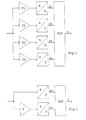
- eine parallele Anordnung von mehreren AD-Wandlern mit vorgeschalteten Vorverstärkern,
- Fig. 2
- eine parallele Anordnung von AD-Wandlern, wobei einem AD-Wandler ein Vorverstärker vorgeschaltet ist.
- Fig. 1
- a parallel arrangement of several AD converters with upstream preamplifiers,
- Fig. 2
- a parallel arrangement of AD converters, an AD converter being preceded by a preamplifier.
Im ersten Beispiel soll ein AD-Wandler aufgebaut werden, der ein analoges Signal im Bereich von 0,1...1 V mit einer Genauigkeit von 1% auflöst. Zur Verfügung stehen 8 bit AD-Wandler mit einer nutzbaren Dynamik von 46 dB und einem Eingangsspannungsbereich von 0...2V. Entsprechend der Beschreibung berechnet sich die maximale zulässige Vorverstärkungsdifferenz zwischen den einzelnen AD-Wandlern zu 6 dB. Der Signalbereich in dem die Auflösung von 1% gefordert wird beträgt 20 dB, woraus sich die minimale Anzahl der benutzten 8-bit AD Wandler mit 3,33 also mit 4 ergibt. Die Vorverstärkungsdifferenz wird nun auf 5 dB festgelegt, und damit die vier Vorverstärker mit V1=6 dB, V2=11 dB, V3=16 dB und V4=21 dB. Es entsteht eine Anordnung nach Fig. 1. Bei diesen kleinen Auflösungen ist eine Offsetkorrektur nicht notwendig, daher kommt eine Anordnung und ein Verfahren entsprechend den Ansprüchen 1 und 2 zur Anwendung. Da der zeitliche Signalverlauf nicht eingeschränkt werden soll, ist es zweckmäßig die Neuberechnung der Verstärkungsdifferenzen nur durchzuführen, wenn ausreichend genaue Wandlungsergebnisse vorliegen, daher kommt ein Verfahren entsprechend den Anspruch 6 zur Anwendung.In the first example, an AD converter is to be built, the one analog signal in the range of 0.1 ... 1 V with an accuracy of 1%. 8 bit AD converters with one are available usable dynamic range of 46 dB and an input voltage range from 0 ... 2V. According to the description, the maximum permissible preamplification difference between the individual AD converters at 6 dB. The signal range in which the resolution of 1% is 20 dB, from which the minimum number of 8-bit AD converters used with 3.33 with 4 results. The pre-gain difference is now set to 5 dB, and thus the four preamplifiers with V1 = 6 dB, V2 = 11 dB, V3 = 16 dB and V4 = 21 dB. An arrangement according to FIG. 1 is created. With these small resolutions there is no offset correction necessary, therefore an arrangement and a procedure come accordingly claims 1 and 2 for use. Because the temporal Signal course should not be restricted, it is appropriate only to recalculate the gain differences, if sufficiently precise conversion results are available, therefore a method according to claim 6 is used.
Da nur unipolare Signale gewandelt werden, kann ein vereinfachtes Verfahren entsprechend den Anspruch 14 verwendet werden. Durch die kleine Verstärkungsdifferenz zwischen den einzelnen AD-Wandlern von nur 5 dB ist es zweckmäßig auch die Schranken sehr genau einzuhalten, weshalb diese automatisch verändert werden und damit der tatsächlichen Verstärkung angepaßt werden sollen. Es wird also ein Verfahren nach den Ansprüchen 18, 19, 23 und 24 verwendet. Die vierfache Kaskadierung der 8 bit AD-Wandler ist im Anspruch 25 beschrieben. Bedingt durch die Grundverstärkung V1 kommt auch das Verfahren und die Anordnung des Anspruchs 26 zur Anwendung.Since only unipolar signals are converted, a simplified one Method according to claim 14 can be used. Due to the small gain difference between the individual AD converters of only 5 dB, it is also useful for the barriers to be followed very precisely, which is why it changes automatically be and thus be adapted to the actual gain should. It is therefore a method according to claims 18, 19, 23 and 24 used. The fourfold cascading of the 8 bits AD converter is described in claim 25. Due to the Basic gain V1 also comes the procedure and arrangement of claim 26 for application.
In einem zweiten Beispiel ist ein AD-Wandler aufzubauen, der ein Audiosignal in einem Bereich von 60 dB mit einem maximalen Klirrfaktor von 0,01%, also einer Klirrdämpfung von 80 dB, wandelt. Zur Verfügung stehen Oversampling-AD-Wandler mit einer Dynamik von 110 dB. Entsprechend der Beschreibung berechnet sich die maximale Verstärkungsdifferenz mit 30 dB und die Anzahl der notwendigen AD-Wandler zu zwei, so daß hier ein Stereo-AD-Wandler zum Einsatz kommen kann. Die zugehörige Anordnung kann der Fig.2 entnommen werden. Bei derartigen AD-Wandlern ist es erforderlich, sowohl Verstärkung als auch Offset in den Algorithmus einzubeziehen. Damit ergibt sich ein Anordnung und ein Verfahren entsprechend dem Anspruch 5. Auch in diesem Fall kann der zeitliche Signalverlauf nicht eingeschränkt werden, insbesondere kann nicht ausgeschlossen werden, daß über einen längeren Zeitraum ein sehr kleines Signal vorhanden ist. Somit ist es zweckmäßig die Neuberechnung der Verstärkungsdifferenzen nur durchzuführen, wenn ausreichend genaue Wandlungsergebnisse vorliegen, daher kommt ein Verfahren entsprechend dem Anspruch 6 zur Anwendung. Für Audiosignale ist es wichtig, daß es bei langsamen Signaländerungen keine Sprünge im Grundrauschen gibt, weshalb auch ein Verfahren nach den Ansprüchen 7 und 8 zur Anwendung kommt. Bedingt durch das Oversamplingverfahren der verwendeten AD-Wandler ist mit einer Signallaufzeit im Reduktionsfilter zu rechnen, weshalb erst nach dem Ablauf einer bestimmten Anzahl von Abtastungen Wandlungsergebnisse des AD-Wandlers mit der größeren Vorverstärkung Einfluß auf das Ausgangssignal der Anordnung haben, entsprechen den Ansprüchen 9 und 10 verwendet werden. Bei ausreichender Rechenkapazität ist weiterhin eine rekursive Berechnung entsprechend dem Anspruch 15 zweckmäßig. Um die Auflösung der verwendeten AD-Wandler voll auszuschöpfen ist auch eine Anpassung aller Schranken entsprechend der Ansprüche 18, 19, 23 und 24 durchzuführen. Durch das Oversamplingverfahren der verwendeten AD-Wandler ist außerdem die Möglichkeit einer internen Übersteuerung bei Signalen, die größer als das 0,7071-fache des Full-Scale-Wertes sind zu beachten, weshalb ein Verfahren nach Anspruch 21 zur Anwendung kommt, wobei die Konstante c den Wert 0,7 besitzt. Bei den verwendeten Oversampling-AD-Wandlern wird üblicher Weise nach dem Einschalten automatisch ein Offsetabgleich durchgeführt. Zweckmäßig ist es daran auch gleich einen Kalibriervorgang anzuschließen um die Verstärkungs- und Offsetwerte zu ermitteln, die für eine fehlerlose Funktion erforderlich sind. Dies erfolgt durch ein Kalibriersignal mit einer Frequenz von etwa 1 kHz und einer Amplitude die zwischen -60 und -33 dB unterhalb des Pegels eines vollausgesteuerten Signals, wobei ein größerer Pegel, aufgrund der dann vorhandenen größeren Auflösung der AD-Wandler, zu einer genaueren Ermittlung der Korrekturwerte führt. Dieses Vorgehen entspricht dem Anspruch 27.In a second example, an AD converter is to be built, the one Audio signal in a range of 60 dB with a maximum Distortion factor of 0.01%, i.e. a distortion attenuation of 80 dB, changes. Oversampling AD converters with one are available Dynamic range of 110 dB. Calculates according to the description the maximum gain difference of 30 dB and the number of necessary AD converter to two, so here is a stereo AD converter can be used. The associated arrangement can be taken from Fig.2. It is with such AD converters required, both gain and offset in the algorithm to involve. This results in an arrangement and a Method according to claim 5. Also in this case the temporal signal curve is not restricted, in particular can not be excluded that over a a very small signal is present for a longer period of time. Consequently it is advisable to recalculate the gain differences only to be carried out if the conversion results are sufficiently precise are present, therefore there is a method according to the claim 6 for use. For audio signals, it is important that the slow signal changes there are no jumps in the noise floor, which is why a method according to claims 7 and 8 for Application comes. Due to the oversampling process of AD converter used has a signal delay in the reduction filter to calculate, which is why only after the expiration of a certain Number of samples conversion results of the AD converter with the greater preamp influence on that Have output signal of the arrangement correspond to the claims 9 and 10 can be used. With sufficient computing capacity furthermore a recursive calculation according to claim 15 expedient. To fully resolve the AD converter used An adaptation of all barriers must also be exploited accordingly of claims 18, 19, 23 and 24. By the oversampling method of the AD converters used is also the possibility of internal override for signals, which are greater than 0.7071 times the full-scale value note why a method according to claim 21 for use comes, where the constant c has the value 0.7. In the used Oversampling AD converters are usually used after the When switching on, an offset adjustment is carried out automatically. Appropriately it is also necessary to immediately connect a calibration process to determine the gain and offset values that are required for correct functioning. this happens by a calibration signal with a frequency of about 1 kHz and an amplitude between -60 and -33 dB below the level of a fully modulated signal, with a larger level due to the larger resolution of the AD converter then available leads to a more precise determination of the correction values. This The procedure corresponds to claim 27.
Claims (27)
Applications Claiming Priority (3)
| Application Number | Priority Date | Filing Date | Title |
|---|---|---|---|
| DE19502047 | 1995-01-12 | ||
| DE19502047A DE19502047C2 (en) | 1995-01-12 | 1995-01-12 | Process for analog-digital conversion of signals |
| EP95250144A EP0707383B1 (en) | 1994-06-14 | 1995-06-14 | Circuit for analogue-digital conversion of signals |
Related Parent Applications (2)
| Application Number | Title | Priority Date | Filing Date |
|---|---|---|---|
| EP95250144.3 Division | 1995-06-14 | ||
| EP95250144A Division EP0707383B1 (en) | 1994-06-14 | 1995-06-14 | Circuit for analogue-digital conversion of signals |
Publications (3)
| Publication Number | Publication Date |
|---|---|
| EP1130782A2 true EP1130782A2 (en) | 2001-09-05 |
| EP1130782A3 EP1130782A3 (en) | 2001-11-21 |
| EP1130782B1 EP1130782B1 (en) | 2013-07-31 |
Family
ID=7752169
Family Applications (1)
| Application Number | Title | Priority Date | Filing Date |
|---|---|---|---|
| EP01109089.1A Expired - Lifetime EP1130782B1 (en) | 1995-01-12 | 1995-06-14 | Method and circuit for the analogue-to-digital conversion of signals |
Country Status (5)
| Country | Link |
|---|---|
| US (1) | US5714956A (en) |
| EP (1) | EP1130782B1 (en) |
| DE (1) | DE19502047C2 (en) |
| DK (1) | DK1130782T3 (en) |
| ES (1) | ES2430547T3 (en) |
Families Citing this family (49)
| Publication number | Priority date | Publication date | Assignee | Title |
|---|---|---|---|---|
| US6333707B1 (en) * | 1998-02-19 | 2001-12-25 | Nortel Networks Limited | Dynamic range extension of wideband receiver |
| SE521566C2 (en) | 1999-10-15 | 2003-11-11 | Ericsson Telefon Ab L M | Method and apparatus for receiving analog signals which vary within a large signal range in a radio communication system |
| US6369740B1 (en) | 1999-10-22 | 2002-04-09 | Eric J. Swanson | Programmable gain preamplifier coupled to an analog to digital converter |
| US6590517B1 (en) | 1999-10-22 | 2003-07-08 | Eric J. Swanson | Analog to digital conversion circuitry including backup conversion circuitry |
| US6310518B1 (en) | 1999-10-22 | 2001-10-30 | Eric J. Swanson | Programmable gain preamplifier |
| US6414619B1 (en) | 1999-10-22 | 2002-07-02 | Eric J. Swanson | Autoranging analog to digital conversion circuitry |
| US6317071B1 (en) * | 2000-08-22 | 2001-11-13 | Lucent Technologies Inc. | Method and apparatus for analog-to-digital conversion by combining digital sample values |
| US7123894B2 (en) * | 2002-12-16 | 2006-10-17 | Harris Corporation | Dynamic range extension system and method |
| DE102005026928B8 (en) * | 2004-07-14 | 2013-05-16 | GAUSS Instruments GmbH Gesellschaft für AUtomatisierte StöremissionsmessSysteme | Method and device for analog-to-digital conversion of an input signal with high dynamics |
| DE102005032982B4 (en) * | 2004-07-14 | 2010-04-22 | Technische Universität München | Method and device for analog-to-digital conversion of an input signal |
| JP2006119723A (en) * | 2004-10-19 | 2006-05-11 | Canon Inc | Device and method for image processing |
| GB2425227B (en) * | 2005-04-15 | 2009-09-02 | Sony Uk Ltd | Analogue to digital conversion |
| GB2425226B (en) * | 2005-04-15 | 2009-07-29 | Sony Uk Ltd | Analogue to digital conversion |
| WO2006109013A1 (en) * | 2005-04-15 | 2006-10-19 | Sony United Kingdom Limited | Analogue to digital conversion |
| DE102007021166A1 (en) * | 2007-05-05 | 2008-11-20 | Teconcept Gmbh | adaptive dynamic extension facilitating method for analog-to digital converter, involves supplying adapted digital channel signal with high analog preamplification, to common output, where preamplification is detected as overload-free |
| US7952502B2 (en) * | 2008-08-29 | 2011-05-31 | Broadcom Corporation | Imbalance and distortion cancellation for composite analog to digital converter (ADC) |
| US7911368B2 (en) * | 2008-10-24 | 2011-03-22 | Olympus Ndt | Sample error minimization for high dynamic range digitization systems |
| EP2207264B1 (en) * | 2009-01-09 | 2013-10-30 | AKG Acoustics GmbH | Analogue to digital converting |
| JP5097858B2 (en) * | 2009-12-04 | 2012-12-12 | 本田技研工業株式会社 | Resolver digital converter |
| US8217822B2 (en) * | 2010-11-09 | 2012-07-10 | Microsoft Corporation | Resolution enhancing analog-to-digital conversion |
| US9467777B2 (en) | 2013-03-15 | 2016-10-11 | Cirrus Logic, Inc. | Interface for a digital microphone array |
| US9831843B1 (en) | 2013-09-05 | 2017-11-28 | Cirrus Logic, Inc. | Opportunistic playback state changes for audio devices |
| US9391576B1 (en) | 2013-09-05 | 2016-07-12 | Cirrus Logic, Inc. | Enhancement of dynamic range of audio signal path |
| US9525940B1 (en) | 2014-03-05 | 2016-12-20 | Cirrus Logic, Inc. | Multi-path analog front end and analog-to-digital converter for a signal processing system |
| US9774342B1 (en) * | 2014-03-05 | 2017-09-26 | Cirrus Logic, Inc. | Multi-path analog front end and analog-to-digital converter for a signal processing system |
| US9306588B2 (en) | 2014-04-14 | 2016-04-05 | Cirrus Logic, Inc. | Switchable secondary playback path |
| CN104066036A (en) * | 2014-06-19 | 2014-09-24 | 华为技术有限公司 | Pick-up device and method |
| US10785568B2 (en) | 2014-06-26 | 2020-09-22 | Cirrus Logic, Inc. | Reducing audio artifacts in a system for enhancing dynamic range of audio signal path |
| US9337795B2 (en) | 2014-09-09 | 2016-05-10 | Cirrus Logic, Inc. | Systems and methods for gain calibration of an audio signal path |
| US9596537B2 (en) | 2014-09-11 | 2017-03-14 | Cirrus Logic, Inc. | Systems and methods for reduction of audio artifacts in an audio system with dynamic range enhancement |
| US9503027B2 (en) | 2014-10-27 | 2016-11-22 | Cirrus Logic, Inc. | Systems and methods for dynamic range enhancement using an open-loop modulator in parallel with a closed-loop modulator |
| CA2973142C (en) | 2015-02-16 | 2018-02-06 | Sound Devices, LLC | High dynamic range analog-to-digital conversion with selective regression based data repair |
| US9584911B2 (en) | 2015-03-27 | 2017-02-28 | Cirrus Logic, Inc. | Multichip dynamic range enhancement (DRE) audio processing methods and apparatuses |
| US9959856B2 (en) | 2015-06-15 | 2018-05-01 | Cirrus Logic, Inc. | Systems and methods for reducing artifacts and improving performance of a multi-path analog-to-digital converter |
| US9955254B2 (en) | 2015-11-25 | 2018-04-24 | Cirrus Logic, Inc. | Systems and methods for preventing distortion due to supply-based modulation index changes in an audio playback system |
| US9543975B1 (en) | 2015-12-29 | 2017-01-10 | Cirrus Logic, Inc. | Multi-path analog front end and analog-to-digital converter for a signal processing system with low-pass filter between paths |
| US9880802B2 (en) | 2016-01-21 | 2018-01-30 | Cirrus Logic, Inc. | Systems and methods for reducing audio artifacts from switching between paths of a multi-path signal processing system |
| US9998826B2 (en) | 2016-06-28 | 2018-06-12 | Cirrus Logic, Inc. | Optimization of performance and power in audio system |
| US10545561B2 (en) | 2016-08-10 | 2020-01-28 | Cirrus Logic, Inc. | Multi-path digitation based on input signal fidelity and output requirements |
| US10263630B2 (en) | 2016-08-11 | 2019-04-16 | Cirrus Logic, Inc. | Multi-path analog front end with adaptive path |
| US9813814B1 (en) | 2016-08-23 | 2017-11-07 | Cirrus Logic, Inc. | Enhancing dynamic range based on spectral content of signal |
| US9762255B1 (en) | 2016-09-19 | 2017-09-12 | Cirrus Logic, Inc. | Reconfiguring paths in a multiple path analog-to-digital converter |
| US9780800B1 (en) | 2016-09-19 | 2017-10-03 | Cirrus Logic, Inc. | Matching paths in a multiple path analog-to-digital converter |
| US9929703B1 (en) | 2016-09-27 | 2018-03-27 | Cirrus Logic, Inc. | Amplifier with configurable final output stage |
| US9967665B2 (en) | 2016-10-05 | 2018-05-08 | Cirrus Logic, Inc. | Adaptation of dynamic range enhancement based on noise floor of signal |
| US10321230B2 (en) | 2017-04-07 | 2019-06-11 | Cirrus Logic, Inc. | Switching in an audio system with multiple playback paths |
| US10008992B1 (en) | 2017-04-14 | 2018-06-26 | Cirrus Logic, Inc. | Switching in amplifier with configurable final output stage |
| US9917557B1 (en) | 2017-04-17 | 2018-03-13 | Cirrus Logic, Inc. | Calibration for amplifier with configurable final output stage |
| WO2019036579A1 (en) | 2017-08-18 | 2019-02-21 | Cirrus Logic International Semiconductor, Ltd. | Multi-path analog system with multi-mode high-pass filter |
Citations (2)
| Publication number | Priority date | Publication date | Assignee | Title |
|---|---|---|---|---|
| EP0346605A2 (en) | 1988-06-14 | 1989-12-20 | ANT Nachrichtentechnik GmbH | High resolution AD or DA converter |
| US4999628A (en) | 1989-06-29 | 1991-03-12 | Yamaha Corporation | Analog-to-digital converting unit with broad dynamic range |
Family Cites Families (10)
| Publication number | Priority date | Publication date | Assignee | Title |
|---|---|---|---|---|
| US4129864A (en) * | 1976-03-03 | 1978-12-12 | The United States Of America As Represented By The Secretary Of Commerce | High speed, wide dynamic range analog-to-digital conversion |
| FR2441956A1 (en) * | 1978-11-17 | 1980-06-13 | Inst Francais Du Petrole | MULTIPLEX SIGNAL AMPLIFICATION METHOD AND IMPLEMENTATION DEVICE |
| DE3603833A1 (en) * | 1986-02-07 | 1987-08-13 | Ant Nachrichtentech | DEVICE FOR ANALOG / DIGITAL CONVERSION OF ELECTRICAL ANALOG SIGNALS |
| EP0265448A1 (en) * | 1986-03-24 | 1988-05-04 | EASTMAN KODAK COMPANY (a New Jersey corporation) | Analog/digital converter apparatus for quantizing transmittance voltage signals |
| DE3611922A1 (en) * | 1986-04-09 | 1987-10-22 | Pierburg Gmbh & Co Kg | Method and device for improving the resolution in the digitisation of an analog signal |
| JPH01131918A (en) * | 1987-11-17 | 1989-05-24 | Hitachi Ltd | A/d converter |
| DE3816903A1 (en) * | 1988-05-18 | 1989-11-30 | Asea Brown Boveri | Method and arrangement for analog/digital conversion |
| FR2649212B1 (en) * | 1989-06-28 | 1991-10-18 | Inst Francais Du Petrole | ACQUISITION METHOD AND DEVICE FOR PRECISE DIGITIZATION OF ANALOG SIGNALS |
| DE4312697A1 (en) * | 1993-04-20 | 1994-10-27 | Leybold Ag | Device for digitizing an analog voltage |
| US5499027A (en) * | 1994-02-24 | 1996-03-12 | Massachusetts Institute Of Technology | Digitally self-calibrating pipeline analog-to-digital converter |
-
1995
- 1995-01-12 DE DE19502047A patent/DE19502047C2/en not_active Expired - Lifetime
- 1995-06-14 DK DK01109089.1T patent/DK1130782T3/en active
- 1995-06-14 EP EP01109089.1A patent/EP1130782B1/en not_active Expired - Lifetime
- 1995-06-14 ES ES01109089T patent/ES2430547T3/en not_active Expired - Lifetime
-
1996
- 1996-01-11 US US08/584,535 patent/US5714956A/en not_active Expired - Lifetime
Patent Citations (2)
| Publication number | Priority date | Publication date | Assignee | Title |
|---|---|---|---|---|
| EP0346605A2 (en) | 1988-06-14 | 1989-12-20 | ANT Nachrichtentechnik GmbH | High resolution AD or DA converter |
| US4999628A (en) | 1989-06-29 | 1991-03-12 | Yamaha Corporation | Analog-to-digital converting unit with broad dynamic range |
Also Published As
| Publication number | Publication date |
|---|---|
| DE19502047A1 (en) | 1996-08-08 |
| US5714956A (en) | 1998-02-03 |
| ES2430547T3 (en) | 2013-11-21 |
| DE19502047C2 (en) | 1996-12-05 |
| DK1130782T3 (en) | 2013-10-28 |
| EP1130782A3 (en) | 2001-11-21 |
| EP1130782B1 (en) | 2013-07-31 |
Similar Documents
| Publication | Publication Date | Title |
|---|---|---|
| EP1130782A2 (en) | Method and circuit for the analogue-to-digital conversion of signals | |
| EP0707383B1 (en) | Circuit for analogue-digital conversion of signals | |
| DE3426068C2 (en) | ||
| EP2041874B1 (en) | Method for processing sensor signals subject to an offset and sensor arrangement designed to carry out the method | |
| DE2820425C2 (en) | Binary random noise generator for stochastic coding | |
| DE102007042315B3 (en) | Measuring circuit with switched capacitor for measuring the capacitance of an input capacitor | |
| DE10235062B4 (en) | Filter method and A / D converter device with a filter function | |
| EP0431214A1 (en) | Analog to digital converter | |
| DE3935617C2 (en) | ||
| DE102009051233B4 (en) | Electronic device and method for impedance measurement | |
| DE19844663C2 (en) | Circuit arrangement and method for setting switching points of a decision maker | |
| DE3525472A1 (en) | ARRANGEMENT FOR DETECTING PULSE-LIKE INTERFERENCE AND ARRANGEMENT FOR SUPPRESSING PULSE-LIKE INTERFERENCE WITH AN ARRANGEMENT FOR DETECTING PULSE-LIKE INTERFERENCE | |
| DE19828399C1 (en) | High speed digital to analog converter for PWM output signals of lambda-probe in motor vehicle | |
| DE102005026928B4 (en) | Method and device for analog-to-digital conversion of an input signal with high dynamics | |
| WO1990014717A1 (en) | High linearity d/a converter | |
| EP0346605A2 (en) | High resolution AD or DA converter | |
| DE19955342A1 (en) | Arrangement for measuring the effective value of an AC voltage over a large dynamic range, in particular for measuring the electrical line | |
| EP0014398B1 (en) | Device for the contactless measuring of thickness or distance | |
| EP0942564A2 (en) | Method for detecting a pulsed signal | |
| EP3141877A2 (en) | Device and method for operating passive infrared sensors | |
| DE3112243C2 (en) | Distortion meter | |
| DE10005605B4 (en) | Analog pre-stage | |
| DE3119975C2 (en) | Homodyne network analysis method | |
| EP0360936A1 (en) | Method for the conversion of a sampled analog input signal | |
| EP1091214A2 (en) | Method and device for processing measuring signals |
Legal Events
| Date | Code | Title | Description |
|---|---|---|---|
| PUAI | Public reference made under article 153(3) epc to a published international application that has entered the european phase |
Free format text: ORIGINAL CODE: 0009012 |
|
| 17P | Request for examination filed |
Effective date: 20010426 |
|
| AC | Divisional application: reference to earlier application |
Ref document number: 707383 Country of ref document: EP |
|
| AK | Designated contracting states |
Kind code of ref document: A2 Designated state(s): AT CH DK ES FR GB IT LI LU NL SE |
|
| RIN1 | Information on inventor provided before grant (corrected) |
Inventor name: KUTSCHABSKY, DETLEF Inventor name: ALTENBERG, OLAF Inventor name: CAIN, KLAUS Inventor name: JAHNE, HELMUT, DR. |
|
| PUAL | Search report despatched |
Free format text: ORIGINAL CODE: 0009013 |
|
| AK | Designated contracting states |
Kind code of ref document: A3 Designated state(s): AT CH DK ES FR GB IT LI LU NL SE |
|
| RIC1 | Information provided on ipc code assigned before grant |
Free format text: 7H 03M 1/10 A, 7H 03M 1/18 - |
|
| AKX | Designation fees paid |
Free format text: AT CH DK ES FR GB IT LI LU NL SE |
|
| 17Q | First examination report despatched |
Effective date: 20050506 |
|
| APBN | Date of receipt of notice of appeal recorded |
Free format text: ORIGINAL CODE: EPIDOSNNOA2E |
|
| APAZ | Date of receipt of statement of grounds of appeal deleted |
Free format text: ORIGINAL CODE: EPIDOSDNOA3E |
|
| APBR | Date of receipt of statement of grounds of appeal recorded |
Free format text: ORIGINAL CODE: EPIDOSNNOA3E |
|
| APAF | Appeal reference modified |
Free format text: ORIGINAL CODE: EPIDOSCREFNE |
|
| APBT | Appeal procedure closed |
Free format text: ORIGINAL CODE: EPIDOSNNOA9E |
|
| APBV | Interlocutory revision of appeal recorded |
Free format text: ORIGINAL CODE: EPIDOSNIRAPE |
|
| GRAP | Despatch of communication of intention to grant a patent |
Free format text: ORIGINAL CODE: EPIDOSNIGR1 |
|
| GRAP | Despatch of communication of intention to grant a patent |
Free format text: ORIGINAL CODE: EPIDOSNIGR1 |
|
| GRAS | Grant fee paid |
Free format text: ORIGINAL CODE: EPIDOSNIGR3 |
|
| GRAA | (expected) grant |
Free format text: ORIGINAL CODE: 0009210 |
|
| AC | Divisional application: reference to earlier application |
Ref document number: 0707383 Country of ref document: EP Kind code of ref document: P |
|
| AK | Designated contracting states |
Kind code of ref document: B1 Designated state(s): AT CH DK ES FR GB IT LI LU NL SE |
|
| REG | Reference to a national code |
Ref country code: GB Ref legal event code: FG4D Free format text: NOT ENGLISH Ref country code: CH Ref legal event code: EP |
|
| REG | Reference to a national code |
Ref country code: AT Ref legal event code: REF Ref document number: 625146 Country of ref document: AT Kind code of ref document: T Effective date: 20130815 |
|
| REG | Reference to a national code |
Ref country code: DK Ref legal event code: T3 Effective date: 20131022 Ref country code: DK Ref legal event code: T3 |
|
| REG | Reference to a national code |
Ref country code: SE Ref legal event code: TRGR |
|
| REG | Reference to a national code |
Ref country code: CH Ref legal event code: NV Representative=s name: PATENTANWALT DIPL.-ING. (UNI.) WOLFGANG HEISEL, CH |
|
| REG | Reference to a national code |
Ref country code: NL Ref legal event code: T3 |
|
| REG | Reference to a national code |
Ref country code: ES Ref legal event code: FG2A Ref document number: 2430547 Country of ref document: ES Kind code of ref document: T3 Effective date: 20131121 |
|
| PLBE | No opposition filed within time limit |
Free format text: ORIGINAL CODE: 0009261 |
|
| STAA | Information on the status of an ep patent application or granted ep patent |
Free format text: STATUS: NO OPPOSITION FILED WITHIN TIME LIMIT |
|
| 26N | No opposition filed |
Effective date: 20140502 |
|
| PGFP | Annual fee paid to national office [announced via postgrant information from national office to epo] |
Ref country code: GB Payment date: 20140618 Year of fee payment: 20 |
|
| PGFP | Annual fee paid to national office [announced via postgrant information from national office to epo] |
Ref country code: CH Payment date: 20140618 Year of fee payment: 20 Ref country code: NL Payment date: 20140618 Year of fee payment: 20 Ref country code: AT Payment date: 20140611 Year of fee payment: 20 Ref country code: LU Payment date: 20140624 Year of fee payment: 20 Ref country code: SE Payment date: 20140618 Year of fee payment: 20 Ref country code: ES Payment date: 20140627 Year of fee payment: 20 |
|
| PGFP | Annual fee paid to national office [announced via postgrant information from national office to epo] |
Ref country code: DK Payment date: 20140618 Year of fee payment: 20 |
|
| PGFP | Annual fee paid to national office [announced via postgrant information from national office to epo] |
Ref country code: FR Payment date: 20140619 Year of fee payment: 20 |
|
| PGFP | Annual fee paid to national office [announced via postgrant information from national office to epo] |
Ref country code: IT Payment date: 20140630 Year of fee payment: 20 |
|
| REG | Reference to a national code |
Ref country code: CH Ref legal event code: PL Ref country code: DK Ref legal event code: EUP Effective date: 20150614 |
|
| REG | Reference to a national code |
Ref country code: NL Ref legal event code: V4 Effective date: 20150614 |
|
| REG | Reference to a national code |
Ref country code: GB Ref legal event code: PE20 Expiry date: 20150613 |
|
| PG25 | Lapsed in a contracting state [announced via postgrant information from national office to epo] |
Ref country code: GB Free format text: LAPSE BECAUSE OF EXPIRATION OF PROTECTION Effective date: 20150613 |
|
| REG | Reference to a national code |
Ref country code: SE Ref legal event code: EUG |
|
| REG | Reference to a national code |
Ref country code: AT Ref legal event code: MK07 Ref document number: 625146 Country of ref document: AT Kind code of ref document: T Effective date: 20150614 |
|
| REG | Reference to a national code |
Ref country code: ES Ref legal event code: FD2A Effective date: 20150925 |
|
| PG25 | Lapsed in a contracting state [announced via postgrant information from national office to epo] |
Ref country code: ES Free format text: LAPSE BECAUSE OF EXPIRATION OF PROTECTION Effective date: 20150615 |