EP1130669A1 - Short circuit inspection method for battery and method of manufacturing batteries - Google Patents
Short circuit inspection method for battery and method of manufacturing batteries Download PDFInfo
- Publication number
- EP1130669A1 EP1130669A1 EP01301497A EP01301497A EP1130669A1 EP 1130669 A1 EP1130669 A1 EP 1130669A1 EP 01301497 A EP01301497 A EP 01301497A EP 01301497 A EP01301497 A EP 01301497A EP 1130669 A1 EP1130669 A1 EP 1130669A1
- Authority
- EP
- European Patent Office
- Prior art keywords
- plate group
- electrode plate
- short
- battery
- electrode plates
- Prior art date
- Legal status (The legal status is an assumption and is not a legal conclusion. Google has not performed a legal analysis and makes no representation as to the accuracy of the status listed.)
- Granted
Links
Images

Classifications
-
- H—ELECTRICITY
- H01—ELECTRIC ELEMENTS
- H01M—PROCESSES OR MEANS, e.g. BATTERIES, FOR THE DIRECT CONVERSION OF CHEMICAL ENERGY INTO ELECTRICAL ENERGY
- H01M10/00—Secondary cells; Manufacture thereof
- H01M10/42—Methods or arrangements for servicing or maintenance of secondary cells or secondary half-cells
- H01M10/48—Accumulators combined with arrangements for measuring, testing or indicating the condition of cells, e.g. the level or density of the electrolyte
-
- G—PHYSICS
- G01—MEASURING; TESTING
- G01R—MEASURING ELECTRIC VARIABLES; MEASURING MAGNETIC VARIABLES
- G01R31/00—Arrangements for testing electric properties; Arrangements for locating electric faults; Arrangements for electrical testing characterised by what is being tested not provided for elsewhere
- G01R31/36—Arrangements for testing, measuring or monitoring the electrical condition of accumulators or electric batteries, e.g. capacity or state of charge [SoC]
- G01R31/385—Arrangements for measuring battery or accumulator variables
- G01R31/3865—Arrangements for measuring battery or accumulator variables related to manufacture, e.g. testing after manufacture
-
- H—ELECTRICITY
- H01—ELECTRIC ELEMENTS
- H01M—PROCESSES OR MEANS, e.g. BATTERIES, FOR THE DIRECT CONVERSION OF CHEMICAL ENERGY INTO ELECTRICAL ENERGY
- H01M10/00—Secondary cells; Manufacture thereof
- H01M10/04—Construction or manufacture in general
- H01M10/0413—Large-sized flat cells or batteries for motive or stationary systems with plate-like electrodes
-
- H—ELECTRICITY
- H01—ELECTRIC ELEMENTS
- H01M—PROCESSES OR MEANS, e.g. BATTERIES, FOR THE DIRECT CONVERSION OF CHEMICAL ENERGY INTO ELECTRICAL ENERGY
- H01M10/00—Secondary cells; Manufacture thereof
- H01M10/42—Methods or arrangements for servicing or maintenance of secondary cells or secondary half-cells
- H01M10/4285—Testing apparatus
-
- G—PHYSICS
- G01—MEASURING; TESTING
- G01R—MEASURING ELECTRIC VARIABLES; MEASURING MAGNETIC VARIABLES
- G01R31/00—Arrangements for testing electric properties; Arrangements for locating electric faults; Arrangements for electrical testing characterised by what is being tested not provided for elsewhere
- G01R31/50—Testing of electric apparatus, lines, cables or components for short-circuits, continuity, leakage current or incorrect line connections
- G01R31/52—Testing for short-circuits, leakage current or ground faults
-
- H—ELECTRICITY
- H01—ELECTRIC ELEMENTS
- H01M—PROCESSES OR MEANS, e.g. BATTERIES, FOR THE DIRECT CONVERSION OF CHEMICAL ENERGY INTO ELECTRICAL ENERGY
- H01M10/00—Secondary cells; Manufacture thereof
- H01M10/34—Gastight accumulators
- H01M10/345—Gastight metal hydride accumulators
-
- Y—GENERAL TAGGING OF NEW TECHNOLOGICAL DEVELOPMENTS; GENERAL TAGGING OF CROSS-SECTIONAL TECHNOLOGIES SPANNING OVER SEVERAL SECTIONS OF THE IPC; TECHNICAL SUBJECTS COVERED BY FORMER USPC CROSS-REFERENCE ART COLLECTIONS [XRACs] AND DIGESTS
- Y02—TECHNOLOGIES OR APPLICATIONS FOR MITIGATION OR ADAPTATION AGAINST CLIMATE CHANGE
- Y02E—REDUCTION OF GREENHOUSE GAS [GHG] EMISSIONS, RELATED TO ENERGY GENERATION, TRANSMISSION OR DISTRIBUTION
- Y02E60/00—Enabling technologies; Technologies with a potential or indirect contribution to GHG emissions mitigation
- Y02E60/10—Energy storage using batteries
-
- Y—GENERAL TAGGING OF NEW TECHNOLOGICAL DEVELOPMENTS; GENERAL TAGGING OF CROSS-SECTIONAL TECHNOLOGIES SPANNING OVER SEVERAL SECTIONS OF THE IPC; TECHNICAL SUBJECTS COVERED BY FORMER USPC CROSS-REFERENCE ART COLLECTIONS [XRACs] AND DIGESTS
- Y02—TECHNOLOGIES OR APPLICATIONS FOR MITIGATION OR ADAPTATION AGAINST CLIMATE CHANGE
- Y02P—CLIMATE CHANGE MITIGATION TECHNOLOGIES IN THE PRODUCTION OR PROCESSING OF GOODS
- Y02P70/00—Climate change mitigation technologies in the production process for final industrial or consumer products
- Y02P70/50—Manufacturing or production processes characterised by the final manufactured product
Definitions
- the present invention relates to a method of inspecting batteries for a short circuit and to a method of manufacturing batteries.
- FIG. 3 illustrates a prior art arrangement for one such inspection method for batteries.
- reference numeral 21 denotes an electrode plate group composed of a plurality of positive electrodes 22 and a plurality of negative electrodes 23 laminated upon one another with separators 24 interposed therebetween.
- the electrode plate group 21 is housed within a battery case 25.
- An insulation resistance tester 27 is connected across the battery case 25 with which the negative electrodes 23 are in contact and a positive electrode terminal 26 connected to one of the positive electrode plates 22 in the middle. The presence or absence of short circuit is thus determined by measuring the insulation resistance across the opposite electrode terminals.
- Another example disclosed, for example, in Japanese Laid-open Patent Application No. 4-138674 is an inspection apparatus connected to a pair of pushing bars for inserting an electrode plate group into a battery case, in which voltage is applied across the pair of pushing bars during or immediately after insertion of the electrode plate group into the battery case.
- Yet another example disclosed, for example, in Japanese Laid-open Patent Application No. 11-40210 involves applying high voltage across the positive and negative electrodes of an electrode plate group housed within a battery case, prior to injection of electrolyte.
- the electrode plate group is thus inspected for short circuits by detecting a voltage drop due to short-circuiting current.
- this method it is also possible to identify the regions where there is a risk of light short-circuiting.
- batteries are subject to ageing after initial charging and discharging, so as to detect and eliminate defective products.
- this requires a long time for inspection and also high costs, since the entire process for inspection including ageing with respect to defective products which are included in the complete batteries is a complete waste.
- the inspection method disclosed in Japanese Laid-open Patent Application No. 4-138674 productivity is improved by performing inspection simultaneously with the process step for inserting electrode plate groups into battery cases.
- the method provides no solution to the above-mentioned problem that some of the complete batteries turn out to be defective later due to swelling of electrode plates.
- the inspection method disclosed in Japanese Laid-open Patent Application No. 11-40210 has an advantage that even the regions which are likely to produce light short circuits after a while can be identified, but it gives no assurance that no short-circuiting occurs after the complete battery undergoes charging and discharging.
- the present invention is a method of inspecting batteries for a short-circuiting failure, including the steps of:
- Electrode plates are compressed during the short-circuiting inspection, so as to simulate a state wherein the separators are compressed by swelling of the electrode plates after charging and discharging of batteries. Accordingly, although the inspection is performed prior to insertion of the electrode plates into the battery case, it is possible to detect a battery in which a short circuit may occur due to swelling of the electrode plates after charging and discharging of the battery.
- the positive and negative electrode plates and separators may be vacuum dried before being assembled into the electrode plate group, so that the inspection is performed without being affected by ambient humidity.
- the electrode plate group is compressed with such an amount of pressure that the separators are compressed to a dimension equal to a dimension to which the separators would be compressed after a predetermined number of cycles of charge and discharge of the battery. In this way, it is possible to remove batteries which may turn out to be defective after a while due to swelling of electrode plates, and reliability of the inspection is improved.
- the battery is inspected for a short circuit by applying a predetermined voltage across the plurality of positive electrode plates and the plurality of negative electrode plates and by measuring electric current passing thereacross. In this way, potential causes of short circuit, such as minute foreign matters, burrs, or the like, are detected, and hence high reliability of inspection is achieved.
- the voltage applied across the plurality of positive electrode plates and the plurality of negative electrode plates is set to a value that is lower than 2/3 of a threshold voltage of the compressed separators. In this way, inspection is strictly performed without causing damage to the electrode plate groups.
- the present invention also provides a method of manufacturing batteries, including the steps of:
- the manufacturing method of the invention includes the battery inspection method described above, which is performed prior to insertion of the electrode plate group into the battery case, whereby a battery in which short-circuiting is likely to occur due to swelling of electrode plates after charging and discharging of the battery is detected and removed. Accordingly, the method enables production of reliable batteries with high efficiency.
- the manufacturing method may further include a step of vacuum-drying the positive and negative electrode plates and separators before they are assembled into the electrode plate group. In this way, inspection of the battery is performed without being affected by ambient humidity.
- reference numeral 1 denotes an electrode plate group for constituting a nickel metal hydride battery.
- the electrode plate group 1 includes a plurality of positive electrode plates 2 and a plurality of negative electrode plates 3 that are alternately laminated upon one another.
- the positive electrode plates 2 are covered with bag-shaped separators 4 having openings on one side, so that the separators 4 are interposed between each of the positive electrode plates 2 and negative electrode plates 3.
- Side edges on one side of the positive electrode plates 2 and those of the negative electrode plates 3 are protruded outwards in opposite directions, and these protruded side edges of the electrode plates constitute respective lead sections.
- Collector plates 5, 6 made of nickel sheet or nickel-plated steel sheet are abutted perpendicularly on the lead sections of the positive and negative electrode plates, respectively, and joined thereto by welding.
- the positive electrode plates 2 are made of metal foam substrate containing Ni, and the lead sections of the positive electrode plates are composed of the protruded side edges of compressed metal foam substrate, to one side of which lead plates are welded by seam welding or ultrasonic welding.
- the negative electrode plates 3 are made of perforated metal substrate of Ni, coated with active materials in the form of a paste, and the lead sections of the negative electrode plates are composed of the protruded side edges of perforated metal substrate, which are not coated with the active material.
- the separators are composed of a 0.20 mm thick non-woven cloth in the shape of a bag.
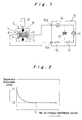
- the electrode plate group 1 thus constructed is set in a pressing station 7 including a pressing jig 8 and a pressure applicator 9, such as a cylinder device, and the positive and negative collector plates 5, 6 are respectively connected to the output terminals 10a, 10b of a short circuit inspection apparatus 10 for detecting short circuits in the electrode plate group 1.
- the short circuit inspection device 10 includes a power source 11, a capacitor 13 connected to the power source 11 via a first switch 12, a current detector 14 connected between the capacitor 13 and one output terminal 10a, and a switch 15 connected between the capacitor 13 and the other output terminal lOb.
- a load of approximately 4000 N is applied to the electrode plate group 1 at the pressing station 7, for the purpose of compressing the thickness of the separators to a predetermined value.
- This amount of compression of the separators is based on the value obtained empirically through repeated charging and discharging of battery. It is known that the thickness of the separators 4 is progressively decreased from the initial thickness tl with repeated charging and discharging of the battery, and stabilizes at t2, after the battery has been used for a predetermined number of cycles, as illustrated in Fig. 2. Generally, the thickness of separators, which had an initial thickness t1 of about 0.20 mm, stabilizes at a value t2 of about 0.13 mm when the number of charge and discharge cycles C of the battery has reached 100.
- the second switch 15 of the short circuit inspection device 10 is opened, while the first switch 12 is closed for charging the capacitor 13.
- the first switch 12 is opened and the second switch 15 is closed, voltage of 400 V is applied to the electrode plate group 1, and the electric current passing through the circuitry is measured by the current detector 14. Since no current should flow if the electrode plate group 1 is free of short circuits, and hence the presence of short circuits is accurately determined.
- the electrode plate group 1 that has passed this short-circuit test is then accommodated inside a prismatic battery case having an opening in the upper end thereof (not illustrated), along with electrolyte solution, and the upper end opening of the battery case is sealed by a lid member (not illustrated), thereby completing a battery.
- electrode plate groups 1 are compressed during the short-circuiting inspection, so as to simulate a state wherein the separators 4 are compressed by swelling of the electrode plates 2, 3 after charging and discharging of batteries. Accordingly, although the inspection is performed prior to insertion of the electrode plate groups into battery cases, it is possible to detect a battery in which a short circuit may occur due to swelling of the electrode plates 2, 3 after charging and discharging of the battery, whereby defective products are reliably eliminated.
- the electrode plate groups 1 are compressed with such an amount that the separators 4 will decrease in thickness to a predetermined value as they would in batteries which have been used for a predetermined number of charge and discharge cycles. In this way, reliability of the inspection is enhanced, and it is prevented that a battery defect occurs at a substantially later time due to swelling of the electrode plates 2, 3.
- voltage applied for inspection is set to a high voltage of approximately 400 V, which is lower than and proximate to 2/3 of the threshold voltage of the compressed separators 4. In this way, inspection is strictly performed without causing damage to the electrode plate groups, and thus inspection reliability is improved.
- the battery inspection method of the invention With the short-circuiting inspection method of the invention described above being incorporated into manufacture of batteries, all potentially defective batteries, in which short circuits can be formed due to swelling of electrode plates 2, 3 after repeated charging and discharging of the batteries, are removed. Accordingly, the battery inspection method of the invention enables production of reliable batteries with good efficiency.
- the short-circuiting inspection method of the invention exhibited an index of 350 in comparison to the value of 100 in accordance with the conventional inspection method, for the detection rate of short circuit failure at the time of inspection. Also, the inspection method of the invention exhibited an index of 38, in comparison to 100 for the conventional method, for the battery failure after use of 1000 cycles of charge and discharge.
- the short circuit inspection method of the invention enables detection of failure at a much higher rate at the time of inspection, as a result of which the fault rate of batteries afterwards is much decreased. It is thus ascertained that the present invention method ensures prevention of short circuit failure in batteries.
Landscapes
- Engineering & Computer Science (AREA)
- Manufacturing & Machinery (AREA)
- Chemical & Material Sciences (AREA)
- Chemical Kinetics & Catalysis (AREA)
- Electrochemistry (AREA)
- General Chemical & Material Sciences (AREA)
- Physics & Mathematics (AREA)
- General Physics & Mathematics (AREA)
- Secondary Cells (AREA)
- Tests Of Electric Status Of Batteries (AREA)
- Testing Of Short-Circuits, Discontinuities, Leakage, Or Incorrect Line Connections (AREA)
Abstract
Description
- The present invention relates to a method of inspecting batteries for a short circuit and to a method of manufacturing batteries.
- Batteries including a number of positive electrodes and negative electrodes with intervening separator therebetween are subject to inspection for a short-circuit failure. Fig. 3 illustrates a prior art arrangement for one such inspection method for batteries. In the drawing,
reference numeral 21 denotes an electrode plate group composed of a plurality ofpositive electrodes 22 and a plurality ofnegative electrodes 23 laminated upon one another withseparators 24 interposed therebetween. Theelectrode plate group 21 is housed within abattery case 25. Aninsulation resistance tester 27 is connected across thebattery case 25 with which thenegative electrodes 23 are in contact and apositive electrode terminal 26 connected to one of thepositive electrode plates 22 in the middle. The presence or absence of short circuit is thus determined by measuring the insulation resistance across the opposite electrode terminals. - Another example disclosed, for example, in Japanese Laid-open Patent Application No. 4-138674 is an inspection apparatus connected to a pair of pushing bars for inserting an electrode plate group into a battery case, in which voltage is applied across the pair of pushing bars during or immediately after insertion of the electrode plate group into the battery case.
- Yet another example disclosed, for example, in Japanese Laid-open Patent Application No. 11-40210 involves applying high voltage across the positive and negative electrodes of an electrode plate group housed within a battery case, prior to injection of electrolyte. The electrode plate group is thus inspected for short circuits by detecting a voltage drop due to short-circuiting current. By this method, it is also possible to identify the regions where there is a risk of light short-circuiting.
- The method illustrated in Fig. 3, wherein the insulation resistance of the
electrode plate group 21 is measured in a state where theelectrode plate group 21 is housed inside abattery case 25, had the following problem. After the battery has been charged and discharged, swelling occurs in the electrode plates, whilst theelectrode plate group 21 is constrained by thebattery case 25, and therefore theseparators 24 interposed between theelectrode plates electrode plates electrode plates separators 24, or due to burrs on theelectrode plates separators 24. Consequently, it is often the case that a battery, which has been determined as satisfactory by the inspection prior to injection of electrolyte into the battery case, will produce short circuit faults after charging and discharging of the battery. - To solve this problem, batteries are subject to ageing after initial charging and discharging, so as to detect and eliminate defective products. However, this requires a long time for inspection and also high costs, since the entire process for inspection including ageing with respect to defective products which are included in the complete batteries is a complete waste.
- Another problem with the method wherein insulation resistance is measured is that it is susceptible to the effects of ambient humidity, resulting in false judgements regarding the presence of short circuits. The method is therefore hardly applicable to the short-circuiting inspection for batteries having a high output design.
- With the inspection method disclosed in Japanese Laid-open Patent Application No. 4-138674, productivity is improved by performing inspection simultaneously with the process step for inserting electrode plate groups into battery cases. However, the method provides no solution to the above-mentioned problem that some of the complete batteries turn out to be defective later due to swelling of electrode plates. The inspection method disclosed in Japanese Laid-open Patent Application No. 11-40210 has an advantage that even the regions which are likely to produce light short circuits after a while can be identified, but it gives no assurance that no short-circuiting occurs after the complete battery undergoes charging and discharging.
- With the foregoing problems of the prior art in view, it is an object of the present invention to provide a battery inspection method, whereby a battery in which short-circuiting may occur after charging and discharging of the battery due to swelling of electrode plates is detected without failure, and a battery manufacturing method wherein such inspection method is incorporated.
- The present invention is a method of inspecting batteries for a short-circuiting failure, including the steps of:
- laminating a plurality of positive electrode plates and a plurality of negative electrode plates alternately with intervening separators therebetween for constituting an electrode plate group; and
- compressing the electrode plate group while inspecting the battery for a short circuit, prior to insertion of the electrode plate group into a battery case.
-
- Electrode plates are compressed during the short-circuiting inspection, so as to simulate a state wherein the separators are compressed by swelling of the electrode plates after charging and discharging of batteries. Accordingly, although the inspection is performed prior to insertion of the electrode plates into the battery case, it is possible to detect a battery in which a short circuit may occur due to swelling of the electrode plates after charging and discharging of the battery.
- The positive and negative electrode plates and separators may be vacuum dried before being assembled into the electrode plate group, so that the inspection is performed without being affected by ambient humidity.
- The electrode plate group is compressed with such an amount of pressure that the separators are compressed to a dimension equal to a dimension to which the separators would be compressed after a predetermined number of cycles of charge and discharge of the battery. In this way, it is possible to remove batteries which may turn out to be defective after a while due to swelling of electrode plates, and reliability of the inspection is improved.
- The battery is inspected for a short circuit by applying a predetermined voltage across the plurality of positive electrode plates and the plurality of negative electrode plates and by measuring electric current passing thereacross. In this way, potential causes of short circuit, such as minute foreign matters, burrs, or the like, are detected, and hence high reliability of inspection is achieved.
- The voltage applied across the plurality of positive electrode plates and the plurality of negative electrode plates is set to a value that is lower than 2/3 of a threshold voltage of the compressed separators. In this way, inspection is strictly performed without causing damage to the electrode plate groups.
- The present invention also provides a method of manufacturing batteries, including the steps of:
- laminating a plurality of positive electrode plates and a plurality of negative electrode plates alternately with intervening separators therebetween for constituting an electrode plate group;
- compressing the electrode plate group while inspecting the battery for a short circuit;
- inserting an electrode plate group that has passed the inspection in the previous step into a battery case;
- injecting electrolyte into the battery case; and
- sealing the battery.
-
- The manufacturing method of the invention includes the battery inspection method described above, which is performed prior to insertion of the electrode plate group into the battery case, whereby a battery in which short-circuiting is likely to occur due to swelling of electrode plates after charging and discharging of the battery is detected and removed. Accordingly, the method enables production of reliable batteries with high efficiency.
- The manufacturing method may further include a step of vacuum-drying the positive and negative electrode plates and separators before they are assembled into the electrode plate group. In this way, inspection of the battery is performed without being affected by ambient humidity.
- Preferred embodiments of the present invention will be hereinafter described with reference to the accompanying drawings, in which:
- Fig. 1 is a schematic diagram showing the arrangement for one embodiment of a battery short circuit inspection method according to the present invention;
- Fig. 2 is a graph illustrating change in separator thickness with the number of charge and discharge cycles of a battery; and
- Fig. 3 is an illustrative diagram of a conventional battery short circuit inspection method.
-
- In Fig. 1,
reference numeral 1 denotes an electrode plate group for constituting a nickel metal hydride battery. Theelectrode plate group 1 includes a plurality of positive electrode plates 2 and a plurality ofnegative electrode plates 3 that are alternately laminated upon one another. The positive electrode plates 2 are covered with bag-shaped separators 4 having openings on one side, so that the separators 4 are interposed between each of the positive electrode plates 2 andnegative electrode plates 3. Side edges on one side of the positive electrode plates 2 and those of thenegative electrode plates 3 are protruded outwards in opposite directions, and these protruded side edges of the electrode plates constitute respective lead sections.Collector plates - The positive electrode plates 2 are made of metal foam substrate containing Ni, and the lead sections of the positive electrode plates are composed of the protruded side edges of compressed metal foam substrate, to one side of which lead plates are welded by seam welding or ultrasonic welding. The
negative electrode plates 3 are made of perforated metal substrate of Ni, coated with active materials in the form of a paste, and the lead sections of the negative electrode plates are composed of the protruded side edges of perforated metal substrate, which are not coated with the active material. The separators are composed of a 0.20 mm thick non-woven cloth in the shape of a bag. These positive electrode plates 2,negative electrode plates 3, and separators 4 are vacuum dried before they are assembled into theelectrode plate group 1, so that the results of inspection in the subsequent process step are not affected by ambient humidity, for ensuring a high degree of inspection accuracy. - The
electrode plate group 1 thus constructed is set in a pressing station 7 including a pressing jig 8 and a pressure applicator 9, such as a cylinder device, and the positive andnegative collector plates output terminals electrode plate group 1. - The short circuit inspection device 10 includes a
power source 11, acapacitor 13 connected to thepower source 11 via afirst switch 12, acurrent detector 14 connected between thecapacitor 13 and oneoutput terminal 10a, and aswitch 15 connected between thecapacitor 13 and the other output terminal lOb. - A load of approximately 4000 N is applied to the
electrode plate group 1 at the pressing station 7, for the purpose of compressing the thickness of the separators to a predetermined value. This amount of compression of the separators is based on the value obtained empirically through repeated charging and discharging of battery. It is known that the thickness of the separators 4 is progressively decreased from the initial thickness tl with repeated charging and discharging of the battery, and stabilizes at t2, after the battery has been used for a predetermined number of cycles, as illustrated in Fig. 2. Generally, the thickness of separators, which had an initial thickness t1 of about 0.20 mm, stabilizes at a value t2 of about 0.13 mm when the number of charge and discharge cycles C of the battery has reached 100. - In the state wherein pressure is applied to the
electrode plate group 1, thesecond switch 15 of the short circuit inspection device 10 is opened, while thefirst switch 12 is closed for charging thecapacitor 13. When charging is finished, thefirst switch 12 is opened and thesecond switch 15 is closed, voltage of 400 V is applied to theelectrode plate group 1, and the electric current passing through the circuitry is measured by thecurrent detector 14. Since no current should flow if theelectrode plate group 1 is free of short circuits, and hence the presence of short circuits is accurately determined. - The
electrode plate group 1 that has passed this short-circuit test is then accommodated inside a prismatic battery case having an opening in the upper end thereof (not illustrated), along with electrolyte solution, and the upper end opening of the battery case is sealed by a lid member (not illustrated), thereby completing a battery. - According to this method, as described above,
electrode plate groups 1 are compressed during the short-circuiting inspection, so as to simulate a state wherein the separators 4 are compressed by swelling of theelectrode plates 2, 3 after charging and discharging of batteries. Accordingly, although the inspection is performed prior to insertion of the electrode plate groups into battery cases, it is possible to detect a battery in which a short circuit may occur due to swelling of theelectrode plates 2, 3 after charging and discharging of the battery, whereby defective products are reliably eliminated. Theelectrode plate groups 1 are compressed with such an amount that the separators 4 will decrease in thickness to a predetermined value as they would in batteries which have been used for a predetermined number of charge and discharge cycles. In this way, reliability of the inspection is enhanced, and it is prevented that a battery defect occurs at a substantially later time due to swelling of theelectrode plates 2, 3. - Since the voltage is applied across the positive and negative electrodes of the
electrode plate group 1 through thecapacitor 13 when measuring the passing electric current by thecurrent detector 14, it is possible to detect even potential causes of short circuits, such as minute impurities, burrs, or the like, and hence high inspection reliability is achieved. In particular, voltage applied for inspection is set to a high voltage of approximately 400 V, which is lower than and proximate to 2/3 of the threshold voltage of the compressed separators 4. In this way, inspection is strictly performed without causing damage to the electrode plate groups, and thus inspection reliability is improved. - With the short-circuiting inspection method of the invention described above being incorporated into manufacture of batteries, all potentially defective batteries, in which short circuits can be formed due to swelling of
electrode plates 2, 3 after repeated charging and discharging of the batteries, are removed. Accordingly, the battery inspection method of the invention enables production of reliable batteries with good efficiency. - The benefits of the invention were confirmed by comparison of the short-circuiting detection rate at the time of inspection according to the short-circuiting inspection method of the invention, and the fault rate of batteries after use of 1000 cycles of charge and discharge, with those in accordance with a conventional method. The results of comparison are summarized in Table 1.
Short-circuiting detection rate at the time of inspection Fault rate of batteries after 1000 cycles of charge/discharge Present Invention 350 38 Prior Art 100 100 - The short-circuiting inspection method of the invention exhibited an index of 350 in comparison to the value of 100 in accordance with the conventional inspection method, for the detection rate of short circuit failure at the time of inspection. Also, the inspection method of the invention exhibited an index of 38, in comparison to 100 for the conventional method, for the battery failure after use of 1000 cycles of charge and discharge.
- It can be seen that the short circuit inspection method of the invention enables detection of failure at a much higher rate at the time of inspection, as a result of which the fault rate of batteries afterwards is much decreased. It is thus ascertained that the present invention method ensures prevention of short circuit failure in batteries.
Claims (6)
- A method of inspecting an electrode plate group for a short-circuit failure, comprising the steps of: laminating a plurality of positive electrode plates (2) and a plurality of negative electrode plates (3) alternately with intervening separators (4) therebetween for constituting an electrode plate group (1); and
compressing said electrode plate group while inspecting them for a short circuit, prior to insertion of said electrode plate group into a battery case. - A method of inspecting an electrode plate group for a short-circuit failure according to Claim 1, wherein said plurality of positive and negative electrode plates and said separators are vacuum dried before being assembled into said electrode plate group.
- A method of inspecting an electrode plate group for a short-circuit failure according to Claim 1 or 2, wherein said electrode plate group is compressed with such an amount of pressure that said separators are compressed to a dimension equal to a dimension to which the separators would be compressed after a predetermined number of cycles of charge and discharge of the completed battery.
- A method of inspecting an electrode plate group for a short-circuit failure according to Claim 1, 2 or 3, wherein said group is inspected for a short circuit by applying a predetermined voltage across said plurality of positive electrode plates and said plurality of negative electrode plates and by measuring electric current passing thereacross.
- A method of inspecting an electrode plate group for a short-circuit failure according to claim 4, wherein the voltage applied across said plurality of positive electrode plates and said plurality of negative electrode plates is set to a value that is lower than 2/3 of a threshold voltage of the compressed separators.
- A method of manufacturing batteries, comprising the steps of:inspecting an electrode plate group for short-circuit failure in accordance with any preceding claim;inserting an electrode plate group that has passed said inspection in the previous step into a battery case;injecting electrolyte into the battery case; andsealing the battery.
Applications Claiming Priority (2)
| Application Number | Priority Date | Filing Date | Title |
|---|---|---|---|
| JP2000044100 | 2000-02-22 | ||
| JP2000044100A JP4666712B2 (en) | 2000-02-22 | 2000-02-22 | Battery short-circuit inspection method |
Publications (2)
| Publication Number | Publication Date |
|---|---|
| EP1130669A1 true EP1130669A1 (en) | 2001-09-05 |
| EP1130669B1 EP1130669B1 (en) | 2003-01-08 |
Family
ID=18566919
Family Applications (1)
| Application Number | Title | Priority Date | Filing Date |
|---|---|---|---|
| EP01301497A Expired - Lifetime EP1130669B1 (en) | 2000-02-22 | 2001-02-20 | Short circuit inspection method for battery and method of manufacturing batteries |
Country Status (4)
| Country | Link |
|---|---|
| US (1) | US6392413B2 (en) |
| EP (1) | EP1130669B1 (en) |
| JP (1) | JP4666712B2 (en) |
| DE (1) | DE60100075T2 (en) |
Cited By (4)
| Publication number | Priority date | Publication date | Assignee | Title |
|---|---|---|---|---|
| EP2093823A4 (en) * | 2006-12-15 | 2010-10-27 | Panasonic Corp | METHOD FOR EVALUATING INTERNAL BATTERY SHORT CIRCUIT, DEVICE FOR EVALUATING INTERNAL BATTERY SHORT CIRCUIT, BATTERY, BATTERY PACK AND METHODS OF MANUFACTURING THE SAME |
| CN102077107A (en) * | 2009-01-19 | 2011-05-25 | 松下电器产业株式会社 | Battery internal short-circuit evaluating device |
| WO2012150017A1 (en) * | 2011-05-05 | 2012-11-08 | Li-Tec Battery Gmbh | Measurement method for an electrochemical energy storage device, and measuring apparatus |
| CN105408755A (en) * | 2013-07-24 | 2016-03-16 | 汽车能源供应公司 | How to check the secondary battery |
Families Citing this family (54)
| Publication number | Priority date | Publication date | Assignee | Title |
|---|---|---|---|---|
| JP4408058B2 (en) * | 2004-05-14 | 2010-02-03 | パナソニック株式会社 | Battery evaluation device |
| JP4218050B2 (en) * | 2004-11-30 | 2009-02-04 | 本田技研工業株式会社 | Voltage measuring apparatus and voltage measuring method |
| US8217658B2 (en) | 2006-12-28 | 2012-07-10 | Panasonic Ev Energy Co., Ltd. | Prismatic battery short circuit inspection method and prismatic battery manufacturing method |
| JP2008192496A (en) * | 2007-02-06 | 2008-08-21 | Matsushita Electric Ind Co Ltd | Battery internal short-circuit evaluation method, battery, battery pack and manufacturing method thereof |
| JP5209896B2 (en) * | 2007-04-24 | 2013-06-12 | パナソニック株式会社 | Battery internal short-circuit safety evaluation method |
| JP5132206B2 (en) * | 2007-06-28 | 2013-01-30 | 三洋電機株式会社 | Evaluation method of separator for non-aqueous electrolyte battery |
| JP4992599B2 (en) * | 2007-08-06 | 2012-08-08 | トヨタ自動車株式会社 | Method and apparatus for inspecting contamination of cylindrical electrode body |
| JP4993196B2 (en) * | 2007-08-23 | 2012-08-08 | トヨタ自動車株式会社 | Method for inspecting wound electrode body and inspection apparatus for wound electrode body |
| JP2010153275A (en) * | 2008-12-26 | 2010-07-08 | Toyota Motor Corp | Method for deciding quality of secondary battery, and method for manufacturing secondary battery |
| JP5270454B2 (en) * | 2009-05-29 | 2013-08-21 | プライムアースEvエナジー株式会社 | Secondary battery sorting method |
| DE102010010600A1 (en) * | 2010-03-08 | 2011-09-08 | Alstom Technology Ltd. | Dual-feed asynchronous machine function monitoring method, involves pressing sheets into composite using bolts, and measuring and evaluating flow of current through source and/or through bolts, where insulation of bolts is measured |
| JP5712928B2 (en) * | 2010-04-06 | 2015-05-07 | 住友電気工業株式会社 | Separator manufacturing method, molten salt battery manufacturing method, separator, and molten salt battery |
| US8736273B2 (en) * | 2010-04-15 | 2014-05-27 | Lg Chem, Ltd. | Testing system and method for testing a battery cell |
| JP5945405B2 (en) | 2011-12-05 | 2016-07-05 | オートモーティブエナジーサプライ株式会社 | Method for producing lithium ion secondary battery |
| US8716981B2 (en) | 2011-11-11 | 2014-05-06 | Lg Chem, Ltd. | System and method for cooling and cycling a battery pack |
| US8816692B2 (en) | 2011-12-01 | 2014-08-26 | Lg Chem, Ltd. | Test system for a battery module |
| CN102636720B (en) * | 2012-04-10 | 2014-09-17 | 东莞市特耐克新能源科技有限公司 | Short circuit testing device and testing method used after lithium ion battery assembly |
| US9063179B2 (en) | 2012-09-26 | 2015-06-23 | Lg Chem, Ltd. | System and method for determining an isolation resistance of a battery pack disposed on a vehicle chassis |
| JP5747895B2 (en) * | 2012-11-06 | 2015-07-15 | トヨタ自動車株式会社 | Manufacturing method of battery pack |
| CN103018624A (en) * | 2012-12-27 | 2013-04-03 | 天津力神电池股份有限公司 | Detection method for plate set short circuit of flexible packaging batteries |
| JP6154164B2 (en) * | 2013-03-21 | 2017-06-28 | オートモーティブエナジーサプライ株式会社 | Battery abnormality detection device and abnormality detection method |
| CN105051967B (en) * | 2013-03-22 | 2017-10-03 | 汽车能源供应公司 | Inspection method of film-encapsulated battery |
| US9164151B2 (en) | 2013-08-07 | 2015-10-20 | Lg Chem, Ltd. | System and method for determining isolation resistances of a battery pack |
| JP6167917B2 (en) * | 2013-09-27 | 2017-07-26 | トヨタ自動車株式会社 | Secondary battery inspection method and inspection device |
| JP5929865B2 (en) * | 2013-10-02 | 2016-06-08 | トヨタ自動車株式会社 | Manufacturing method of secondary battery |
| KR101800051B1 (en) * | 2013-10-31 | 2017-11-21 | 주식회사 엘지화학 | Short measuring apparatus of unit cell |
| KR101826894B1 (en) * | 2013-11-04 | 2018-02-07 | 주식회사 엘지화학 | Electrode assembly and apparatus for manufacturing the same |
| JP6135469B2 (en) * | 2013-11-11 | 2017-05-31 | 株式会社豊田自動織機 | Power storage device inspection method |
| KR101778829B1 (en) * | 2013-11-29 | 2017-09-14 | 주식회사 엘지화학 | Short circuit detection device |
| JP6248751B2 (en) * | 2014-03-28 | 2017-12-20 | 株式会社豊田自動織機 | Power storage device inspection method |
| JP6176220B2 (en) * | 2014-10-14 | 2017-08-09 | トヨタ自動車株式会社 | Inspection device |
| DE102015003228A1 (en) * | 2015-03-13 | 2016-09-15 | Li-Tec Battery Gmbh | Measuring method for detecting the quality or the functionality of an energy storage device |
| JP6401122B2 (en) * | 2015-07-30 | 2018-10-03 | 矢崎総業株式会社 | Secondary battery status detector |
| KR101927257B1 (en) * | 2015-09-09 | 2018-12-10 | 주식회사 엘지화학 | Apparatus of Testing Secondary Battery by Nail Penetration and Method thereof |
| CN106019166B (en) * | 2016-07-27 | 2019-03-15 | 芜湖楚睿智能科技有限公司 | A kind of photovoltaic micro energy-storage battery monitoring method |
| KR102132754B1 (en) * | 2017-06-29 | 2020-07-13 | 주식회사 엘지화학 | Jig apparatus for quality test of secondary battery |
| JP6969997B2 (en) * | 2017-12-08 | 2021-11-24 | 株式会社エンビジョンAescジャパン | Battery manufacturing method and battery conductivity inspection device |
| KR102204699B1 (en) * | 2018-01-31 | 2021-01-18 | 주식회사 엘지화학 | Method and apparatus for evaluating safety of secondary battery |
| KR101980844B1 (en) * | 2018-02-26 | 2019-05-21 | 주식회사 엘지화학 | Method for evaluating insulating performance of separator for electrochemical devidce |
| EP3683589B1 (en) | 2018-06-11 | 2023-03-29 | LG Energy Solution, Ltd. | Simultaneous inspection device of multiple secondary battery cell pouches |
| KR102395248B1 (en) | 2018-08-09 | 2022-05-04 | 주식회사 엘지에너지솔루션 | Apparatus for detecting a defect of battery separator and Detecting method using the same |
| KR102619196B1 (en) * | 2018-10-17 | 2023-12-27 | 주식회사 엘지에너지솔루션 | Apparatus for detecting a low voltage pouch type secondary battery cell |
| KR102408132B1 (en) * | 2018-11-21 | 2022-06-14 | 주식회사 엘지에너지솔루션 | Method for testing pressure short defect by jig pressing |
| CN111381182B (en) * | 2018-12-27 | 2021-01-26 | 广州汽车集团股份有限公司 | A cell short circuit detection fixture, device and detection method |
| JP7090139B2 (en) * | 2019-11-19 | 2022-06-23 | 三洋化成工業株式会社 | Inspection method and manufacturing method of assembled battery |
| EP4064395A4 (en) | 2019-11-19 | 2023-08-02 | APB Corporation | METHOD OF INSPECTION AND METHOD OF MANUFACTURING A BATTERY PACK |
| JP7090683B2 (en) * | 2019-11-19 | 2022-06-24 | 三洋化成工業株式会社 | How to inspect single batteries and how to manufacture assembled batteries |
| KR102940138B1 (en) | 2020-08-12 | 2026-03-16 | 주식회사 엘지에너지솔루션 | Apparatus for detecting a defect of battery separator including a plurality of pressing rollers and method for detecting a defect of battery separator using same |
| KR102751071B1 (en) * | 2020-10-19 | 2025-01-06 | 주식회사 엘지에너지솔루션 | Battery inspection apparatus |
| KR102936605B1 (en) | 2021-07-08 | 2026-03-06 | 주식회사 엘지에너지솔루션 | Battery management system, battery pack, electric vehicle, and battery management method |
| KR20240084394A (en) | 2022-12-06 | 2024-06-13 | 주식회사 엘지에너지솔루션 | Method for Detecting Defect of Separator |
| CN116297487A (en) * | 2023-03-16 | 2023-06-23 | 惠州市赛能电池有限公司 | Analysis method of battery short circuit |
| KR20250151716A (en) * | 2024-04-15 | 2025-10-22 | 삼성에스디아이 주식회사 | Apparatus for checking insulation of separator for Secondary Battery |
| EP4660649A1 (en) * | 2024-06-06 | 2025-12-10 | LG Energy Solution, Ltd. | Method and system for inspection of one or more battery cells |
Citations (5)
| Publication number | Priority date | Publication date | Assignee | Title |
|---|---|---|---|---|
| GB2013964A (en) * | 1978-01-04 | 1979-08-15 | Chloride Group Ltd | Assembling Electric Batteries |
| US4282292A (en) * | 1979-12-31 | 1981-08-04 | General Battery Corporation | Open and short circuit test method |
| JPS5835878A (en) * | 1981-08-28 | 1983-03-02 | Shin Kobe Electric Mach Co Ltd | Inspection method of lead storage battery electrode group |
| JPH04138674A (en) * | 1990-09-28 | 1992-05-13 | Yuasa Corp | Manufacture of storage battery |
| JPH1140210A (en) * | 1997-07-18 | 1999-02-12 | Furukawa Battery Co Ltd:The | Method for inspecting short-circuit of alkaline secondary battery |
Family Cites Families (4)
| Publication number | Priority date | Publication date | Assignee | Title |
|---|---|---|---|---|
| JPS60155985A (en) * | 1984-01-25 | 1985-08-16 | Matsushita Electric Ind Co Ltd | Short circuit inspection device |
| JPH0817463A (en) * | 1994-06-30 | 1996-01-19 | Sanyo Electric Co Ltd | Rectangular sealed battery and its manufacture |
| JP3183139B2 (en) * | 1995-12-15 | 2001-07-03 | 松下電器産業株式会社 | Short-circuit detection method for cylindrical batteries |
| JP3677993B2 (en) * | 1998-04-06 | 2005-08-03 | 松下電器産業株式会社 | Battery electrode group short circuit inspection method and short circuit inspection apparatus therefor |
-
2000
- 2000-02-22 JP JP2000044100A patent/JP4666712B2/en not_active Expired - Fee Related
-
2001
- 2001-02-20 DE DE60100075T patent/DE60100075T2/en not_active Expired - Lifetime
- 2001-02-20 EP EP01301497A patent/EP1130669B1/en not_active Expired - Lifetime
- 2001-02-21 US US09/788,536 patent/US6392413B2/en not_active Expired - Lifetime
Patent Citations (5)
| Publication number | Priority date | Publication date | Assignee | Title |
|---|---|---|---|---|
| GB2013964A (en) * | 1978-01-04 | 1979-08-15 | Chloride Group Ltd | Assembling Electric Batteries |
| US4282292A (en) * | 1979-12-31 | 1981-08-04 | General Battery Corporation | Open and short circuit test method |
| JPS5835878A (en) * | 1981-08-28 | 1983-03-02 | Shin Kobe Electric Mach Co Ltd | Inspection method of lead storage battery electrode group |
| JPH04138674A (en) * | 1990-09-28 | 1992-05-13 | Yuasa Corp | Manufacture of storage battery |
| JPH1140210A (en) * | 1997-07-18 | 1999-02-12 | Furukawa Battery Co Ltd:The | Method for inspecting short-circuit of alkaline secondary battery |
Non-Patent Citations (3)
| Title |
|---|
| PATENT ABSTRACTS OF JAPAN vol. 007, no. 115 (E - 176) 19 May 1983 (1983-05-19) * |
| PATENT ABSTRACTS OF JAPAN vol. 016, no. 412 (E - 1256) 31 August 1992 (1992-08-31) * |
| PATENT ABSTRACTS OF JAPAN vol. 1999, no. 05 31 May 1999 (1999-05-31) * |
Cited By (14)
| Publication number | Priority date | Publication date | Assignee | Title |
|---|---|---|---|---|
| CN102148398A (en) * | 2006-12-15 | 2011-08-10 | 松下电器产业株式会社 | Method for evaluating internal short circuit of battery |
| CN102148399B (en) * | 2006-12-15 | 2013-10-16 | 松下电器产业株式会社 | Method for evaluating internal short circuit of battery |
| EP2337140A1 (en) * | 2006-12-15 | 2011-06-22 | Panasonic Corporation | Method for evaluating internal short-circuit of battery, device for evaluating internal short-circuit of battery, battery, battery pack and their manufacturing methods |
| EP2337138A1 (en) * | 2006-12-15 | 2011-06-22 | Panasonic Corporation | Method for evaluating internal short-circuit of battery, device for evaluating internal short-circuit of battery, battery, battery pack and their manufacturing methods |
| EP2337139A1 (en) * | 2006-12-15 | 2011-06-22 | Panasonic Corporation | Method for evaluating internal short-circuit of battery, device for evaluating internal short-circuit of battery, battery, battery pack and their manufacturing methods |
| CN102148399A (en) * | 2006-12-15 | 2011-08-10 | 松下电器产业株式会社 | Method for evaluating internal short circuit of battery |
| US8168314B2 (en) | 2006-12-15 | 2012-05-01 | Panasonic Corporation | Method for evaluating internal short-circuit of battery, device for evaluating internal short-circuit of battery, battery, battery pack and their manufacturing methods |
| CN102148398B (en) * | 2006-12-15 | 2013-10-16 | 松下电器产业株式会社 | Method for evaluating internal short circuit of battery |
| EP2093823A4 (en) * | 2006-12-15 | 2010-10-27 | Panasonic Corp | METHOD FOR EVALUATING INTERNAL BATTERY SHORT CIRCUIT, DEVICE FOR EVALUATING INTERNAL BATTERY SHORT CIRCUIT, BATTERY, BATTERY PACK AND METHODS OF MANUFACTURING THE SAME |
| CN102077107B (en) * | 2009-01-19 | 2013-07-24 | 松下电器产业株式会社 | Battery internal short circuit evaluation device |
| CN102077107A (en) * | 2009-01-19 | 2011-05-25 | 松下电器产业株式会社 | Battery internal short-circuit evaluating device |
| WO2012150017A1 (en) * | 2011-05-05 | 2012-11-08 | Li-Tec Battery Gmbh | Measurement method for an electrochemical energy storage device, and measuring apparatus |
| CN105408755A (en) * | 2013-07-24 | 2016-03-16 | 汽车能源供应公司 | How to check the secondary battery |
| EP3026450A4 (en) * | 2013-07-24 | 2016-07-20 | Automotive Energy Supply Corp | Secondary battery inspection method |
Also Published As
| Publication number | Publication date |
|---|---|
| DE60100075D1 (en) | 2003-02-13 |
| DE60100075T2 (en) | 2003-11-06 |
| JP4666712B2 (en) | 2011-04-06 |
| US6392413B2 (en) | 2002-05-21 |
| JP2001236985A (en) | 2001-08-31 |
| US20010019270A1 (en) | 2001-09-06 |
| EP1130669B1 (en) | 2003-01-08 |
Similar Documents
| Publication | Publication Date | Title |
|---|---|---|
| EP1130669B1 (en) | Short circuit inspection method for battery and method of manufacturing batteries | |
| JP2001236985A5 (en) | ||
| KR20200059563A (en) | Method for testing pressure short defect by jig pressing | |
| US20160161564A1 (en) | Test method for secondary battery | |
| KR20200059483A (en) | Pressure short testing device for detecting a low voltage battery cell | |
| US7239147B2 (en) | Method and device for inspecting secondary battery precursor and method for manufacturing secondary battery using the inspection method | |
| CN104515954B (en) | The manufacture method of secondary cell | |
| JP4887581B2 (en) | Battery inspection method and inspection apparatus | |
| KR101775213B1 (en) | Inspecting method for electrode assembly and inspecting device for the same | |
| KR102759617B1 (en) | Battery defect screening device and method | |
| JP3677993B2 (en) | Battery electrode group short circuit inspection method and short circuit inspection apparatus therefor | |
| CN116710766B (en) | Equipment for detecting foreign object locations in low-voltage battery cells and analytical methods using the equipment | |
| JP2024501308A (en) | Battery welding condition inspection method | |
| CN115443417A (en) | Method and device for checking the state of a battery | |
| JP2000195565A (en) | Inspection method of secondary battery | |
| JP4666897B2 (en) | Battery manufacturing method | |
| JP5974967B2 (en) | Battery inspection method and battery manufacturing method | |
| KR20180001351A (en) | Method of the electrical and physical defect inspection between Lead-acid battery cell | |
| CN217443480U (en) | Withstand voltage detection frock of electricity core utmost point group | |
| CN114755540A (en) | Withstand voltage detection frock of electricity core utmost point group | |
| JPH09167637A (en) | Cylindrical battery short circuit detection method | |
| JP7778719B2 (en) | Method for detecting micro-short circuits, test stand, and production line | |
| KR20220060972A (en) | Battery defect screening device and method | |
| JPS60155985A (en) | Short circuit inspection device | |
| JPH0367473A (en) | Inspection method for sealed lead-acid battery |
Legal Events
| Date | Code | Title | Description |
|---|---|---|---|
| PUAI | Public reference made under article 153(3) epc to a published international application that has entered the european phase |
Free format text: ORIGINAL CODE: 0009012 |
|
| AK | Designated contracting states |
Kind code of ref document: A1 Designated state(s): AT BE CH CY DE DK ES FI FR GB GR IE IT LI LU MC NL PT SE TR Kind code of ref document: A1 Designated state(s): DE FR GB |
|
| AX | Request for extension of the european patent |
Free format text: AL;LT;LV;MK;RO;SI |
|
| 17P | Request for examination filed |
Effective date: 20020204 |
|
| GRAG | Despatch of communication of intention to grant |
Free format text: ORIGINAL CODE: EPIDOS AGRA |
|
| AKX | Designation fees paid |
Free format text: DE FR GB |
|
| 17Q | First examination report despatched |
Effective date: 20020529 |
|
| GRAG | Despatch of communication of intention to grant |
Free format text: ORIGINAL CODE: EPIDOS AGRA |
|
| GRAH | Despatch of communication of intention to grant a patent |
Free format text: ORIGINAL CODE: EPIDOS IGRA |
|
| GRAH | Despatch of communication of intention to grant a patent |
Free format text: ORIGINAL CODE: EPIDOS IGRA |
|
| GRAA | (expected) grant |
Free format text: ORIGINAL CODE: 0009210 |
|
| AK | Designated contracting states |
Kind code of ref document: B1 Designated state(s): DE FR GB |
|
| REG | Reference to a national code |
Ref country code: GB Ref legal event code: FG4D |
|
| REF | Corresponds to: |
Ref document number: 60100075 Country of ref document: DE Date of ref document: 20030213 Kind code of ref document: P |
|
| ET | Fr: translation filed | ||
| PLBE | No opposition filed within time limit |
Free format text: ORIGINAL CODE: 0009261 |
|
| STAA | Information on the status of an ep patent application or granted ep patent |
Free format text: STATUS: NO OPPOSITION FILED WITHIN TIME LIMIT |
|
| 26N | No opposition filed |
Effective date: 20031009 |
|
| REG | Reference to a national code |
Ref country code: GB Ref legal event code: 746 Effective date: 20090928 |
|
| REG | Reference to a national code |
Ref country code: FR Ref legal event code: PLFP Year of fee payment: 16 |
|
| REG | Reference to a national code |
Ref country code: FR Ref legal event code: PLFP Year of fee payment: 17 |
|
| REG | Reference to a national code |
Ref country code: FR Ref legal event code: PLFP Year of fee payment: 18 |
|
| PGFP | Annual fee paid to national office [announced via postgrant information from national office to epo] |
Ref country code: GB Payment date: 20200212 Year of fee payment: 20 Ref country code: DE Payment date: 20200204 Year of fee payment: 20 |
|
| PGFP | Annual fee paid to national office [announced via postgrant information from national office to epo] |
Ref country code: FR Payment date: 20200113 Year of fee payment: 20 |
|
| REG | Reference to a national code |
Ref country code: DE Ref legal event code: R071 Ref document number: 60100075 Country of ref document: DE |
|
| REG | Reference to a national code |
Ref country code: GB Ref legal event code: PE20 Expiry date: 20210219 |
|
| PG25 | Lapsed in a contracting state [announced via postgrant information from national office to epo] |
Ref country code: GB Free format text: LAPSE BECAUSE OF EXPIRATION OF PROTECTION Effective date: 20210219 |