EP1130662A1 - Electrode structure, electric component and production methods - Google Patents
Electrode structure, electric component and production methods Download PDFInfo
- Publication number
- EP1130662A1 EP1130662A1 EP00951952A EP00951952A EP1130662A1 EP 1130662 A1 EP1130662 A1 EP 1130662A1 EP 00951952 A EP00951952 A EP 00951952A EP 00951952 A EP00951952 A EP 00951952A EP 1130662 A1 EP1130662 A1 EP 1130662A1
- Authority
- EP
- European Patent Office
- Prior art keywords
- ion
- substance
- powdered
- conducting
- electrode structure
- Prior art date
- Legal status (The legal status is an assumption and is not a legal conclusion. Google has not performed a legal analysis and makes no representation as to the accuracy of the status listed.)
- Withdrawn
Links
- 238000004519 manufacturing process Methods 0.000 title claims abstract description 27
- 239000000126 substance Substances 0.000 claims abstract description 92
- 239000002322 conducting polymer Substances 0.000 claims abstract description 81
- 229920001940 conductive polymer Polymers 0.000 claims abstract description 81
- 239000003792 electrolyte Substances 0.000 claims abstract description 26
- 239000003990 capacitor Substances 0.000 claims abstract description 22
- 239000013543 active substance Substances 0.000 claims description 53
- 239000000203 mixture Substances 0.000 claims description 53
- 239000002994 raw material Substances 0.000 claims description 35
- 239000000463 material Substances 0.000 claims description 25
- 150000002500 ions Chemical class 0.000 claims description 18
- 239000002904 solvent Substances 0.000 claims description 11
- OKTJSMMVPCPJKN-UHFFFAOYSA-N Carbon Chemical compound [C] OKTJSMMVPCPJKN-UHFFFAOYSA-N 0.000 description 37
- 229920000642 polymer Polymers 0.000 description 30
- WEVYAHXRMPXWCK-UHFFFAOYSA-N Acetonitrile Chemical compound CC#N WEVYAHXRMPXWCK-UHFFFAOYSA-N 0.000 description 27
- 239000002245 particle Substances 0.000 description 27
- 230000000052 comparative effect Effects 0.000 description 21
- 229910032387 LiCoO2 Inorganic materials 0.000 description 15
- 239000011230 binding agent Substances 0.000 description 14
- 150000001875 compounds Chemical class 0.000 description 13
- 238000007599 discharging Methods 0.000 description 13
- 238000002156 mixing Methods 0.000 description 13
- 239000006185 dispersion Substances 0.000 description 12
- KMTRUDSVKNLOMY-UHFFFAOYSA-N Ethylene carbonate Chemical compound O=C1OCCO1 KMTRUDSVKNLOMY-UHFFFAOYSA-N 0.000 description 10
- HBBGRARXTFLTSG-UHFFFAOYSA-N Lithium ion Chemical compound [Li+] HBBGRARXTFLTSG-UHFFFAOYSA-N 0.000 description 10
- 229910001416 lithium ion Inorganic materials 0.000 description 10
- 238000012360 testing method Methods 0.000 description 10
- 238000000034 method Methods 0.000 description 9
- 229910052744 lithium Inorganic materials 0.000 description 8
- 238000003892 spreading Methods 0.000 description 8
- 230000007480 spreading Effects 0.000 description 8
- 229910052782 aluminium Inorganic materials 0.000 description 7
- 238000007872 degassing Methods 0.000 description 7
- 239000011888 foil Substances 0.000 description 7
- AVFZOVWCLRSYKC-UHFFFAOYSA-N 1-methylpyrrolidine Chemical compound CN1CCCC1 AVFZOVWCLRSYKC-UHFFFAOYSA-N 0.000 description 6
- WHXSMMKQMYFTQS-UHFFFAOYSA-N Lithium Chemical compound [Li] WHXSMMKQMYFTQS-UHFFFAOYSA-N 0.000 description 6
- AHVYPIQETPWLSZ-UHFFFAOYSA-N N-methyl-pyrrolidine Natural products CN1CC=CC1 AHVYPIQETPWLSZ-UHFFFAOYSA-N 0.000 description 6
- 239000002033 PVDF binder Substances 0.000 description 6
- 230000009471 action Effects 0.000 description 6
- XAGFODPZIPBFFR-UHFFFAOYSA-N aluminium Chemical compound [Al] XAGFODPZIPBFFR-UHFFFAOYSA-N 0.000 description 6
- 238000010586 diagram Methods 0.000 description 6
- 239000011244 liquid electrolyte Substances 0.000 description 6
- 229910003002 lithium salt Inorganic materials 0.000 description 6
- 159000000002 lithium salts Chemical class 0.000 description 6
- 229920002981 polyvinylidene fluoride Polymers 0.000 description 6
- 230000008569 process Effects 0.000 description 6
- BVKZGUZCCUSVTD-UHFFFAOYSA-L Carbonate Chemical compound [O-]C([O-])=O BVKZGUZCCUSVTD-UHFFFAOYSA-L 0.000 description 5
- RYGMFSIKBFXOCR-UHFFFAOYSA-N Copper Chemical compound [Cu] RYGMFSIKBFXOCR-UHFFFAOYSA-N 0.000 description 5
- 239000003575 carbonaceous material Substances 0.000 description 5
- 238000000635 electron micrograph Methods 0.000 description 5
- WYGWHHGCAGTUCH-UHFFFAOYSA-N 2-[(2-cyano-4-methylpentan-2-yl)diazenyl]-2,4-dimethylpentanenitrile Chemical compound CC(C)CC(C)(C#N)N=NC(C)(C#N)CC(C)C WYGWHHGCAGTUCH-UHFFFAOYSA-N 0.000 description 4
- 150000001786 chalcogen compounds Chemical class 0.000 description 4
- 239000011889 copper foil Substances 0.000 description 4
- 230000007423 decrease Effects 0.000 description 4
- 238000003780 insertion Methods 0.000 description 4
- 230000037431 insertion Effects 0.000 description 4
- 229910052751 metal Inorganic materials 0.000 description 4
- 239000002184 metal Substances 0.000 description 4
- 238000000926 separation method Methods 0.000 description 4
- 238000009736 wetting Methods 0.000 description 4
- 229920003026 Acene Polymers 0.000 description 3
- LYCAIKOWRPUZTN-UHFFFAOYSA-N Ethylene glycol Chemical compound OCCO LYCAIKOWRPUZTN-UHFFFAOYSA-N 0.000 description 3
- ISWSIDIOOBJBQZ-UHFFFAOYSA-N Phenol Chemical compound OC1=CC=CC=C1 ISWSIDIOOBJBQZ-UHFFFAOYSA-N 0.000 description 3
- 239000004372 Polyvinyl alcohol Substances 0.000 description 3
- DNIAPMSPPWPWGF-UHFFFAOYSA-N Propylene glycol Chemical compound CC(O)CO DNIAPMSPPWPWGF-UHFFFAOYSA-N 0.000 description 3
- 230000003213 activating effect Effects 0.000 description 3
- 229910052799 carbon Inorganic materials 0.000 description 3
- 239000011248 coating agent Substances 0.000 description 3
- 238000000576 coating method Methods 0.000 description 3
- 238000010276 construction Methods 0.000 description 3
- 238000001035 drying Methods 0.000 description 3
- 238000010304 firing Methods 0.000 description 3
- 239000007788 liquid Substances 0.000 description 3
- 239000011255 nonaqueous electrolyte Substances 0.000 description 3
- 230000035515 penetration Effects 0.000 description 3
- 239000002006 petroleum coke Substances 0.000 description 3
- -1 polytetrafluoroethylene-hexafluoropropylene copolymer Polymers 0.000 description 3
- 229920002451 polyvinyl alcohol Polymers 0.000 description 3
- 239000000843 powder Substances 0.000 description 3
- 238000003825 pressing Methods 0.000 description 3
- 238000012545 processing Methods 0.000 description 3
- 229920000049 Carbon (fiber) Polymers 0.000 description 2
- 229910000733 Li alloy Inorganic materials 0.000 description 2
- SECXISVLQFMRJM-UHFFFAOYSA-N N-Methylpyrrolidone Chemical compound CN1CCCC1=O SECXISVLQFMRJM-UHFFFAOYSA-N 0.000 description 2
- PXHVJJICTQNCMI-UHFFFAOYSA-N Nickel Chemical compound [Ni] PXHVJJICTQNCMI-UHFFFAOYSA-N 0.000 description 2
- OKKRPWIIYQTPQF-UHFFFAOYSA-N Trimethylolpropane trimethacrylate Chemical compound CC(=C)C(=O)OCC(CC)(COC(=O)C(C)=C)COC(=O)C(C)=C OKKRPWIIYQTPQF-UHFFFAOYSA-N 0.000 description 2
- QVGXLLKOCUKJST-UHFFFAOYSA-N atomic oxygen Chemical compound [O] QVGXLLKOCUKJST-UHFFFAOYSA-N 0.000 description 2
- 239000006229 carbon black Substances 0.000 description 2
- 239000004917 carbon fiber Substances 0.000 description 2
- 239000001913 cellulose Substances 0.000 description 2
- 229920002678 cellulose Polymers 0.000 description 2
- GNTDGMZSJNCJKK-UHFFFAOYSA-N divanadium pentaoxide Chemical compound O=[V](=O)O[V](=O)=O GNTDGMZSJNCJKK-UHFFFAOYSA-N 0.000 description 2
- 238000007580 dry-mixing Methods 0.000 description 2
- 230000000694 effects Effects 0.000 description 2
- 230000005611 electricity Effects 0.000 description 2
- 239000010419 fine particle Substances 0.000 description 2
- 239000011245 gel electrolyte Substances 0.000 description 2
- 229910002804 graphite Inorganic materials 0.000 description 2
- 239000010439 graphite Substances 0.000 description 2
- 238000005087 graphitization Methods 0.000 description 2
- 239000003273 ketjen black Substances 0.000 description 2
- 229920000126 latex Polymers 0.000 description 2
- 239000004816 latex Substances 0.000 description 2
- 229910052748 manganese Inorganic materials 0.000 description 2
- 239000011572 manganese Substances 0.000 description 2
- NUJOXMJBOLGQSY-UHFFFAOYSA-N manganese dioxide Chemical compound O=[Mn]=O NUJOXMJBOLGQSY-UHFFFAOYSA-N 0.000 description 2
- 238000005259 measurement Methods 0.000 description 2
- 125000005641 methacryl group Chemical group 0.000 description 2
- VNWKTOKETHGBQD-UHFFFAOYSA-N methane Chemical compound C VNWKTOKETHGBQD-UHFFFAOYSA-N 0.000 description 2
- 239000003960 organic solvent Substances 0.000 description 2
- 229910052760 oxygen Inorganic materials 0.000 description 2
- 239000001301 oxygen Substances 0.000 description 2
- 229920005596 polymer binder Polymers 0.000 description 2
- 239000002491 polymer binding agent Substances 0.000 description 2
- 229920002635 polyurethane Polymers 0.000 description 2
- 239000004814 polyurethane Substances 0.000 description 2
- 239000002296 pyrolytic carbon Substances 0.000 description 2
- 150000003839 salts Chemical class 0.000 description 2
- 239000002002 slurry Substances 0.000 description 2
- 239000007784 solid electrolyte Substances 0.000 description 2
- 239000007858 starting material Substances 0.000 description 2
- 238000003756 stirring Methods 0.000 description 2
- 229920003048 styrene butadiene rubber Polymers 0.000 description 2
- 230000002889 sympathetic effect Effects 0.000 description 2
- 238000007751 thermal spraying Methods 0.000 description 2
- WFKWXMTUELFFGS-UHFFFAOYSA-N tungsten Chemical compound [W] WFKWXMTUELFFGS-UHFFFAOYSA-N 0.000 description 2
- 229910052721 tungsten Inorganic materials 0.000 description 2
- 239000010937 tungsten Substances 0.000 description 2
- WSGYTJNNHPZFKR-UHFFFAOYSA-N 3-hydroxypropanenitrile Chemical compound OCCC#N WSGYTJNNHPZFKR-UHFFFAOYSA-N 0.000 description 1
- 229910017048 AsF6 Inorganic materials 0.000 description 1
- KRHYYFGTRYWZRS-UHFFFAOYSA-M Fluoride anion Chemical compound [F-] KRHYYFGTRYWZRS-UHFFFAOYSA-M 0.000 description 1
- 229910002993 LiMnO2 Inorganic materials 0.000 description 1
- 229910003005 LiNiO2 Inorganic materials 0.000 description 1
- 229910002097 Lithium manganese(III,IV) oxide Inorganic materials 0.000 description 1
- 229910014514 LixNiyM1-yO2 Inorganic materials 0.000 description 1
- 229910014512 LixNiyM1−yO2 Inorganic materials 0.000 description 1
- PWHULOQIROXLJO-UHFFFAOYSA-N Manganese Chemical compound [Mn] PWHULOQIROXLJO-UHFFFAOYSA-N 0.000 description 1
- CERQOIWHTDAKMF-UHFFFAOYSA-M Methacrylate Chemical compound CC(=C)C([O-])=O CERQOIWHTDAKMF-UHFFFAOYSA-M 0.000 description 1
- 241000047703 Nonion Species 0.000 description 1
- 239000004698 Polyethylene Substances 0.000 description 1
- NINIDFKCEFEMDL-UHFFFAOYSA-N Sulfur Chemical compound [S] NINIDFKCEFEMDL-UHFFFAOYSA-N 0.000 description 1
- 229910003092 TiS2 Inorganic materials 0.000 description 1
- 230000001154 acute effect Effects 0.000 description 1
- 239000000654 additive Substances 0.000 description 1
- 230000000996 additive effect Effects 0.000 description 1
- 239000000853 adhesive Substances 0.000 description 1
- 230000001070 adhesive effect Effects 0.000 description 1
- 150000001450 anions Chemical class 0.000 description 1
- MTAZNLWOLGHBHU-UHFFFAOYSA-N butadiene-styrene rubber Chemical class C=CC=C.C=CC1=CC=CC=C1 MTAZNLWOLGHBHU-UHFFFAOYSA-N 0.000 description 1
- 238000010000 carbonizing Methods 0.000 description 1
- 239000007809 chemical reaction catalyst Substances 0.000 description 1
- 229910001914 chlorine tetroxide Inorganic materials 0.000 description 1
- 229910052804 chromium Inorganic materials 0.000 description 1
- 239000004927 clay Substances 0.000 description 1
- 229910017052 cobalt Inorganic materials 0.000 description 1
- 239000010941 cobalt Substances 0.000 description 1
- GUTLYIVDDKVIGB-UHFFFAOYSA-N cobalt atom Chemical compound [Co] GUTLYIVDDKVIGB-UHFFFAOYSA-N 0.000 description 1
- 239000000571 coke Substances 0.000 description 1
- 229920003243 conjugated conducting polymer Polymers 0.000 description 1
- 229910052802 copper Inorganic materials 0.000 description 1
- 239000010949 copper Substances 0.000 description 1
- 238000004132 cross linking Methods 0.000 description 1
- 239000007772 electrode material Substances 0.000 description 1
- 125000002573 ethenylidene group Chemical group [*]=C=C([H])[H] 0.000 description 1
- 238000004880 explosion Methods 0.000 description 1
- 238000011049 filling Methods 0.000 description 1
- 239000007849 furan resin Substances 0.000 description 1
- 239000011521 glass Substances 0.000 description 1
- 238000000227 grinding Methods 0.000 description 1
- 229910021385 hard carbon Inorganic materials 0.000 description 1
- GPRLSGONYQIRFK-UHFFFAOYSA-N hydron Chemical compound [H+] GPRLSGONYQIRFK-UHFFFAOYSA-N 0.000 description 1
- 150000004679 hydroxides Chemical class 0.000 description 1
- 238000005470 impregnation Methods 0.000 description 1
- 229910052738 indium Inorganic materials 0.000 description 1
- APFVFJFRJDLVQX-UHFFFAOYSA-N indium atom Chemical compound [In] APFVFJFRJDLVQX-UHFFFAOYSA-N 0.000 description 1
- 150000002641 lithium Chemical class 0.000 description 1
- 239000001989 lithium alloy Substances 0.000 description 1
- 229910052960 marcasite Inorganic materials 0.000 description 1
- 229910052961 molybdenite Inorganic materials 0.000 description 1
- CWQXQMHSOZUFJS-UHFFFAOYSA-N molybdenum disulfide Chemical compound S=[Mo]=S CWQXQMHSOZUFJS-UHFFFAOYSA-N 0.000 description 1
- 229910052982 molybdenum disulfide Inorganic materials 0.000 description 1
- 239000004570 mortar (masonry) Substances 0.000 description 1
- 239000011331 needle coke Substances 0.000 description 1
- 229910052759 nickel Inorganic materials 0.000 description 1
- 229920000620 organic polymer Polymers 0.000 description 1
- 230000000149 penetrating effect Effects 0.000 description 1
- VLTRZXGMWDSKGL-UHFFFAOYSA-M perchlorate Chemical compound [O-]Cl(=O)(=O)=O VLTRZXGMWDSKGL-UHFFFAOYSA-M 0.000 description 1
- 229920001568 phenolic resin Polymers 0.000 description 1
- 239000005011 phenolic resin Substances 0.000 description 1
- 239000006253 pitch coke Substances 0.000 description 1
- 229920001197 polyacetylene Polymers 0.000 description 1
- 229920000767 polyaniline Polymers 0.000 description 1
- 229920001088 polycarbazole Polymers 0.000 description 1
- 229920000573 polyethylene Polymers 0.000 description 1
- 229920005862 polyol Polymers 0.000 description 1
- 150000003077 polyols Chemical class 0.000 description 1
- 229920000128 polypyrrole Polymers 0.000 description 1
- 229920000123 polythiophene Polymers 0.000 description 1
- NIFIFKQPDTWWGU-UHFFFAOYSA-N pyrite Chemical compound [Fe+2].[S-][S-] NIFIFKQPDTWWGU-UHFFFAOYSA-N 0.000 description 1
- 229910052683 pyrite Inorganic materials 0.000 description 1
- 230000005855 radiation Effects 0.000 description 1
- 229920005604 random copolymer Polymers 0.000 description 1
- 239000011347 resin Substances 0.000 description 1
- 229920005989 resin Polymers 0.000 description 1
- 230000000630 rising effect Effects 0.000 description 1
- 239000000523 sample Substances 0.000 description 1
- 238000007789 sealing Methods 0.000 description 1
- 239000007787 solid Substances 0.000 description 1
- 238000003860 storage Methods 0.000 description 1
- 229910052717 sulfur Inorganic materials 0.000 description 1
- 239000011593 sulfur Substances 0.000 description 1
- 239000003115 supporting electrolyte Substances 0.000 description 1
- 229910052719 titanium Inorganic materials 0.000 description 1
- 229910052723 transition metal Inorganic materials 0.000 description 1
- 150000003624 transition metals Chemical class 0.000 description 1
- 229910052720 vanadium Inorganic materials 0.000 description 1
- XLYOFNOQVPJJNP-UHFFFAOYSA-N water Substances O XLYOFNOQVPJJNP-UHFFFAOYSA-N 0.000 description 1
- 238000004804 winding Methods 0.000 description 1
Images






Classifications
-
- H—ELECTRICITY
- H01—ELECTRIC ELEMENTS
- H01G—CAPACITORS; CAPACITORS, RECTIFIERS, DETECTORS, SWITCHING DEVICES, LIGHT-SENSITIVE OR TEMPERATURE-SENSITIVE DEVICES OF THE ELECTROLYTIC TYPE
- H01G11/00—Hybrid capacitors, i.e. capacitors having different positive and negative electrodes; Electric double-layer [EDL] capacitors; Processes for the manufacture thereof or of parts thereof
- H01G11/22—Electrodes
- H01G11/26—Electrodes characterised by their structure, e.g. multi-layered, porosity or surface features
- H01G11/28—Electrodes characterised by their structure, e.g. multi-layered, porosity or surface features arranged or disposed on a current collector; Layers or phases between electrodes and current collectors, e.g. adhesives
-
- H—ELECTRICITY
- H01—ELECTRIC ELEMENTS
- H01M—PROCESSES OR MEANS, e.g. BATTERIES, FOR THE DIRECT CONVERSION OF CHEMICAL ENERGY INTO ELECTRICAL ENERGY
- H01M4/00—Electrodes
- H01M4/02—Electrodes composed of, or comprising, active material
- H01M4/64—Carriers or collectors
-
- H—ELECTRICITY
- H01—ELECTRIC ELEMENTS
- H01G—CAPACITORS; CAPACITORS, RECTIFIERS, DETECTORS, SWITCHING DEVICES, LIGHT-SENSITIVE OR TEMPERATURE-SENSITIVE DEVICES OF THE ELECTROLYTIC TYPE
- H01G11/00—Hybrid capacitors, i.e. capacitors having different positive and negative electrodes; Electric double-layer [EDL] capacitors; Processes for the manufacture thereof or of parts thereof
- H01G11/22—Electrodes
- H01G11/30—Electrodes characterised by their material
- H01G11/32—Carbon-based
- H01G11/38—Carbon pastes or blends; Binders or additives therein
-
- H—ELECTRICITY
- H01—ELECTRIC ELEMENTS
- H01G—CAPACITORS; CAPACITORS, RECTIFIERS, DETECTORS, SWITCHING DEVICES, LIGHT-SENSITIVE OR TEMPERATURE-SENSITIVE DEVICES OF THE ELECTROLYTIC TYPE
- H01G11/00—Hybrid capacitors, i.e. capacitors having different positive and negative electrodes; Electric double-layer [EDL] capacitors; Processes for the manufacture thereof or of parts thereof
- H01G11/52—Separators
-
- H—ELECTRICITY
- H01—ELECTRIC ELEMENTS
- H01G—CAPACITORS; CAPACITORS, RECTIFIERS, DETECTORS, SWITCHING DEVICES, LIGHT-SENSITIVE OR TEMPERATURE-SENSITIVE DEVICES OF THE ELECTROLYTIC TYPE
- H01G11/00—Hybrid capacitors, i.e. capacitors having different positive and negative electrodes; Electric double-layer [EDL] capacitors; Processes for the manufacture thereof or of parts thereof
- H01G11/54—Electrolytes
- H01G11/56—Solid electrolytes, e.g. gels; Additives therein
-
- H—ELECTRICITY
- H01—ELECTRIC ELEMENTS
- H01G—CAPACITORS; CAPACITORS, RECTIFIERS, DETECTORS, SWITCHING DEVICES, LIGHT-SENSITIVE OR TEMPERATURE-SENSITIVE DEVICES OF THE ELECTROLYTIC TYPE
- H01G11/00—Hybrid capacitors, i.e. capacitors having different positive and negative electrodes; Electric double-layer [EDL] capacitors; Processes for the manufacture thereof or of parts thereof
- H01G11/84—Processes for the manufacture of hybrid or EDL capacitors, or components thereof
-
- H—ELECTRICITY
- H01—ELECTRIC ELEMENTS
- H01M—PROCESSES OR MEANS, e.g. BATTERIES, FOR THE DIRECT CONVERSION OF CHEMICAL ENERGY INTO ELECTRICAL ENERGY
- H01M10/00—Secondary cells; Manufacture thereof
- H01M10/05—Accumulators with non-aqueous electrolyte
- H01M10/052—Li-accumulators
-
- H—ELECTRICITY
- H01—ELECTRIC ELEMENTS
- H01M—PROCESSES OR MEANS, e.g. BATTERIES, FOR THE DIRECT CONVERSION OF CHEMICAL ENERGY INTO ELECTRICAL ENERGY
- H01M10/00—Secondary cells; Manufacture thereof
- H01M10/05—Accumulators with non-aqueous electrolyte
- H01M10/052—Li-accumulators
- H01M10/0525—Rocking-chair batteries, i.e. batteries with lithium insertion or intercalation in both electrodes; Lithium-ion batteries
-
- H—ELECTRICITY
- H01—ELECTRIC ELEMENTS
- H01M—PROCESSES OR MEANS, e.g. BATTERIES, FOR THE DIRECT CONVERSION OF CHEMICAL ENERGY INTO ELECTRICAL ENERGY
- H01M4/00—Electrodes
- H01M4/02—Electrodes composed of, or comprising, active material
- H01M4/04—Processes of manufacture in general
- H01M4/0402—Methods of deposition of the material
-
- H—ELECTRICITY
- H01—ELECTRIC ELEMENTS
- H01M—PROCESSES OR MEANS, e.g. BATTERIES, FOR THE DIRECT CONVERSION OF CHEMICAL ENERGY INTO ELECTRICAL ENERGY
- H01M4/00—Electrodes
- H01M4/02—Electrodes composed of, or comprising, active material
- H01M4/04—Processes of manufacture in general
- H01M4/0402—Methods of deposition of the material
- H01M4/0404—Methods of deposition of the material by coating on electrode collectors
-
- H—ELECTRICITY
- H01—ELECTRIC ELEMENTS
- H01M—PROCESSES OR MEANS, e.g. BATTERIES, FOR THE DIRECT CONVERSION OF CHEMICAL ENERGY INTO ELECTRICAL ENERGY
- H01M4/00—Electrodes
- H01M4/02—Electrodes composed of, or comprising, active material
- H01M4/04—Processes of manufacture in general
- H01M4/0402—Methods of deposition of the material
- H01M4/0409—Methods of deposition of the material by a doctor blade method, slip-casting or roller coating
-
- H—ELECTRICITY
- H01—ELECTRIC ELEMENTS
- H01M—PROCESSES OR MEANS, e.g. BATTERIES, FOR THE DIRECT CONVERSION OF CHEMICAL ENERGY INTO ELECTRICAL ENERGY
- H01M4/00—Electrodes
- H01M4/02—Electrodes composed of, or comprising, active material
- H01M4/04—Processes of manufacture in general
- H01M4/0402—Methods of deposition of the material
- H01M4/0416—Methods of deposition of the material involving impregnation with a solution, dispersion, paste or dry powder
-
- H—ELECTRICITY
- H01—ELECTRIC ELEMENTS
- H01M—PROCESSES OR MEANS, e.g. BATTERIES, FOR THE DIRECT CONVERSION OF CHEMICAL ENERGY INTO ELECTRICAL ENERGY
- H01M4/00—Electrodes
- H01M4/02—Electrodes composed of, or comprising, active material
- H01M4/04—Processes of manufacture in general
- H01M4/043—Processes of manufacture in general involving compressing or compaction
- H01M4/0435—Rolling or calendering
-
- H—ELECTRICITY
- H01—ELECTRIC ELEMENTS
- H01M—PROCESSES OR MEANS, e.g. BATTERIES, FOR THE DIRECT CONVERSION OF CHEMICAL ENERGY INTO ELECTRICAL ENERGY
- H01M4/00—Electrodes
- H01M4/02—Electrodes composed of, or comprising, active material
- H01M4/13—Electrodes for accumulators with non-aqueous electrolyte, e.g. for lithium-accumulators; Processes of manufacture thereof
-
- H—ELECTRICITY
- H01—ELECTRIC ELEMENTS
- H01M—PROCESSES OR MEANS, e.g. BATTERIES, FOR THE DIRECT CONVERSION OF CHEMICAL ENERGY INTO ELECTRICAL ENERGY
- H01M4/00—Electrodes
- H01M4/02—Electrodes composed of, or comprising, active material
- H01M4/13—Electrodes for accumulators with non-aqueous electrolyte, e.g. for lithium-accumulators; Processes of manufacture thereof
- H01M4/139—Processes of manufacture
- H01M4/1399—Processes of manufacture of electrodes based on electro-active polymers
-
- H—ELECTRICITY
- H01—ELECTRIC ELEMENTS
- H01M—PROCESSES OR MEANS, e.g. BATTERIES, FOR THE DIRECT CONVERSION OF CHEMICAL ENERGY INTO ELECTRICAL ENERGY
- H01M4/00—Electrodes
- H01M4/02—Electrodes composed of, or comprising, active material
- H01M4/62—Selection of inactive substances as ingredients for active masses, e.g. binders, fillers
- H01M4/621—Binders
-
- H—ELECTRICITY
- H01—ELECTRIC ELEMENTS
- H01M—PROCESSES OR MEANS, e.g. BATTERIES, FOR THE DIRECT CONVERSION OF CHEMICAL ENERGY INTO ELECTRICAL ENERGY
- H01M4/00—Electrodes
- H01M4/02—Electrodes composed of, or comprising, active material
- H01M4/62—Selection of inactive substances as ingredients for active masses, e.g. binders, fillers
- H01M4/621—Binders
- H01M4/622—Binders being polymers
-
- H—ELECTRICITY
- H01—ELECTRIC ELEMENTS
- H01G—CAPACITORS; CAPACITORS, RECTIFIERS, DETECTORS, SWITCHING DEVICES, LIGHT-SENSITIVE OR TEMPERATURE-SENSITIVE DEVICES OF THE ELECTROLYTIC TYPE
- H01G11/00—Hybrid capacitors, i.e. capacitors having different positive and negative electrodes; Electric double-layer [EDL] capacitors; Processes for the manufacture thereof or of parts thereof
- H01G11/22—Electrodes
- H01G11/30—Electrodes characterised by their material
- H01G11/48—Conductive polymers
-
- H—ELECTRICITY
- H01—ELECTRIC ELEMENTS
- H01M—PROCESSES OR MEANS, e.g. BATTERIES, FOR THE DIRECT CONVERSION OF CHEMICAL ENERGY INTO ELECTRICAL ENERGY
- H01M2300/00—Electrolytes
- H01M2300/0017—Non-aqueous electrolytes
- H01M2300/0065—Solid electrolytes
- H01M2300/0082—Organic polymers
-
- H—ELECTRICITY
- H01—ELECTRIC ELEMENTS
- H01M—PROCESSES OR MEANS, e.g. BATTERIES, FOR THE DIRECT CONVERSION OF CHEMICAL ENERGY INTO ELECTRICAL ENERGY
- H01M4/00—Electrodes
- H01M4/02—Electrodes composed of, or comprising, active material
-
- H—ELECTRICITY
- H01—ELECTRIC ELEMENTS
- H01M—PROCESSES OR MEANS, e.g. BATTERIES, FOR THE DIRECT CONVERSION OF CHEMICAL ENERGY INTO ELECTRICAL ENERGY
- H01M4/00—Electrodes
- H01M4/02—Electrodes composed of, or comprising, active material
- H01M4/13—Electrodes for accumulators with non-aqueous electrolyte, e.g. for lithium-accumulators; Processes of manufacture thereof
- H01M4/131—Electrodes based on mixed oxides or hydroxides, or on mixtures of oxides or hydroxides, e.g. LiCoOx
-
- Y—GENERAL TAGGING OF NEW TECHNOLOGICAL DEVELOPMENTS; GENERAL TAGGING OF CROSS-SECTIONAL TECHNOLOGIES SPANNING OVER SEVERAL SECTIONS OF THE IPC; TECHNICAL SUBJECTS COVERED BY FORMER USPC CROSS-REFERENCE ART COLLECTIONS [XRACs] AND DIGESTS
- Y02—TECHNOLOGIES OR APPLICATIONS FOR MITIGATION OR ADAPTATION AGAINST CLIMATE CHANGE
- Y02E—REDUCTION OF GREENHOUSE GAS [GHG] EMISSIONS, RELATED TO ENERGY GENERATION, TRANSMISSION OR DISTRIBUTION
- Y02E60/00—Enabling technologies; Technologies with a potential or indirect contribution to GHG emissions mitigation
- Y02E60/10—Energy storage using batteries
-
- Y—GENERAL TAGGING OF NEW TECHNOLOGICAL DEVELOPMENTS; GENERAL TAGGING OF CROSS-SECTIONAL TECHNOLOGIES SPANNING OVER SEVERAL SECTIONS OF THE IPC; TECHNICAL SUBJECTS COVERED BY FORMER USPC CROSS-REFERENCE ART COLLECTIONS [XRACs] AND DIGESTS
- Y02—TECHNOLOGIES OR APPLICATIONS FOR MITIGATION OR ADAPTATION AGAINST CLIMATE CHANGE
- Y02E—REDUCTION OF GREENHOUSE GAS [GHG] EMISSIONS, RELATED TO ENERGY GENERATION, TRANSMISSION OR DISTRIBUTION
- Y02E60/00—Enabling technologies; Technologies with a potential or indirect contribution to GHG emissions mitigation
- Y02E60/13—Energy storage using capacitors
Definitions
- This invention relates to an electrode structure using an ion-conducting polymer, and to an electrical component such as a primary cell, a secondary cell, and an electric double layer capacitor.
- a positive electrode h is manufactured by mixing a mixture e of a powdered electrode active substance a comprising LiCoO 2 , powdered electrically-conducting carbon b , a binder polymer c and a solvent d into a slurry, and applying it to a current-collecting member f to form a compound film g , as shown in Fig. 13.
- the compound film g of Fig. 13 is a partial enlargement of the mixture e on the current-collecting member f.
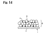
- a negative electrode i is manufactured by mixing the mixture e of the powdered electrode active substance a comprising powdered graphite, the binder polymer c and the solvent d into a slurry, applying it to the current-collecting member f , and drying to form the compound film g, as shown in Fig. 14.
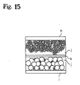
- a lithium secondary cell contains an electrolyte j between the positive electrode h and negative electrode i , a separator k being disposed in the electrolyte j , as shown in Fig. 15.
- the lithium secondary cell is generally formed by applying a dispersion of the electrode active substance a or the binder c in an organic solvent to a current-collecting member f comprising metal foil or the like, drying, winding a sheet electrode comprising the compound film g into a spiral shape together with the separator k , inserting this spiral-shaped electrode into a battery case, filling with the organic solvent electrolyte j , and sealing.
- This battery is characterized by having a high energy density per unit capacity and high energy density per unit weight.
- the binder polymer c which is generally used does not have ion-conducting properties.
- the binder polymer c may be vinylidene polyfluoride, a fluoride resin such as polytetrafluoroethylene-hexafluoropropylene copolymer, styrene-butadiene rubber latex or carboxyl-modified styrene-butadiene rubber latex.
- the strength of the compound film g decreases, so cohesion between the electrode active substance a or electron-conducting assistant and the current-collecting member f gradually declines during repeated charges and discharges of the battery, and battery performance declines due to decrease of electron-conducting properties.
- Japanese Patent Laid-Open Hei 10-106540 discloses a method of forming the binder polymer c as a mesh.
- the binder polymer c which is used is a non-ion conducting polymer, so ions cannot penetrate or move through the binder polymer c . Therefore, in this case also, penetration of lithium ions into the electrode active substance a is blocked as in the case of a prior art electrode. As a result, the battery performance declines.
- Batteries are used for various types of electrical components, and they have to satisfy stringent safety criteria with regard to fire, etc.
- oxygen is generated if the LiCoO 2 is heated to high temperature and as there is a risk of explosion or fire if a large current flows due to a short-circuit, safety is a prime consideration.
- This invention specifically relates to:
- Fig. 1 is a diagram showing the manufacture of an electrode structure comprising an electrode active substance which supplies ions.
- Fig. 2 is a diagram of an electrode structure comprising an electrically conducting substance wherein electricity moves between ions.
- Fig. 3 is a schematic view of a secondary cell.
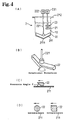
- Fig. 4 is a descriptive diagram of a pressure-sliding mixer.
- Fig. 5 is a schematic view of the press-sliding mixer wherein the bottom surface of a container is flat.
- Fig. 6 is another schematic view of the press-sliding mixer.
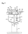
- Fig. 7 is a front view of the press-sliding mixer.
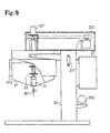
- Fig. 8 is a lateral view of the press-sliding mixer.
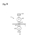
- Fig. 9 is a descriptive diagram of a cohesion device.
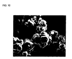
- Fig. 10 is an electron micrograph of LiCoO 2 which has not received any processing.
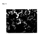
- Fig. 11 is an electron micrograph of a positive electrode structure obtained in a third embodiment.
- Fig. 12 is a photograph of a secondary electronic image of the positive electrode structure obtained in the third embodiment.
- Fig. 13 is a diagram showing the manufacture of a positive electrode structure of a secondary cell according to the prior art.
- Fig. 14 is a diagram showing the manufacture of a negative electrode structure of a secondary cell according to the prior art.
- Fig. 15 is a schematic view of a secondary cell according to the prior art.
- Electrodes wherein ions migrate between electrodes are those in which an ion-conducting substance is disposed between electrode structures functioning as electrodes, and ions migrate within the ion-conducting substance so that a current flows between the electrodes, e.g., primary cells, secondary cells, and an electric double layer capacitor.
- Batteries are characterized in that an ion-conducting substance disposed between the positive electrode structure and negative electrode structure and that an ion, including a proton or a positive hydrogen ion, migrates between electrodes and is accumulated.
- An electric double layer capacitor is characterized in that an ion-conducting substance is disposed between a pair of electrode structures and an electric double layer is formed between a large surface material within the electrode structures and an electrolyte of the ion-conducting substance.
- Electrode structures are used as electrodes in these electrical components, and exchange electrical charges with ions or draw ions.
- they have a construction in which a powdered electrode substance coated with an ion-conducting polymer, is made to adhere to a current-collecting member.
- they have a construction in which the powdered electrode active substance used for batteries or a powdered large surface material with a large surface area used for an electric double layer capacitor is made to adhere to a current-collecting member.
- Fig. 1 shows a process for manufacturing an electrode structure 1 wherein a powdered electrode substance, i.e., a powdered electrode active substance 11, comprising particles of a compound such as LiCoO 2 is coated with an ion-conducting polymer 12, and is made to adhere to a current-collecting member 13.
- Fig. 2 shows a process for manufacturing the electrode structure 1 wherein a powdered electrode substance, i.e., the powdered electrode active substance 11 having a form such as that of graphite or hard carbon is coated with the ion-conducting polymer 12, and is made to adhere to the current-collecting member 13.
- a powdered large surface material such as an activated carbon as the powdered electrode substance may be coated with the ion-conducting polymer and is adhered to the current-collecting member to form an electrode structure of the electric double layer capacitor.
- Fig. 1 shows the case where the electrical conductivity of the powdered electrode active substance 11 is low.
- the electrical conductivity in the powdered electrode active substance and between the powdered electrode active substance 11 and current-collecting member 13, is increased and the current-collecting efficiency improved by mixing with a powdered electrically-conducting substance 14.
- the powdered electrically-conducting substance 14 may or may not be coated with the ion-conducting polymer.
- Coating refers to a state of contact wherein ions can easily migrate between the ion-conducting polymer 12 and the powdered electrode substance, i.e., the powdered electrode active substance 11 over their entire surfaces or the powdered large surface material over their entire surfaces.
- the ion-conducting polymer 12 is coated on the surface of the powdered electrode active substance 11 or the powdered large surface material so that the latter is covered by the ion-conducting polymer 12.
- the powdered electrode active substance 11 becomes more active the finer the particles of which it is comprised, but its activity can be suppressed to give greater stability by coating with the ion-conducting polymer 12.
- the layer of the coated ion-conducting polymer 12 is thick, conductivity decreases and current-collecting efficiency is poorer, so it is preferably thin.
- powdered electrode active substance 11 the powdered electrically-conducting substance 14, or the powdered large surface material refers to a substance having a fine particle state. In some cases, it may refer to a state wherein a large number of substances having a fine particle state are agglomerated.
- the powdered electrode active substance may be a material which permits insertion and separation of ions, or a ⁇ -conjugated electrically-conducting polymer material.
- Electrode active material used as the positive electrode in a non-aqueous electrolytic battery there is no particular limitation on the electrode active material used as the positive electrode in a non-aqueous electrolytic battery, but in the case of a rechargeable secondary cell, a chalcogen compound permitting insertion and separation of lithium ions or a complex chalcogen compound containing lithium may for example be used.
- Examples of chalcogen compounds are FeS 2 , TiS 2 , MoS 2 , V 2 O 5 , V 6 O 13 and MnO 2 .
- Examples of chalcogen compounds containing lithium are LiCoO 2 , lithium complexes represented by LixNiyM 1 -yO 2 (where M is at least one metal element chosen from transition metals or Al, but preferably at least one metal element chosen from Co, Mn, Ti, Cr, V and Al, and 0.05 ⁇ x ⁇ 1.10, 0.5 ⁇ y ⁇ 1.0), LiNiO 2 , LiMnO 2 and LiMn 2 O 4 .
- These compounds may be obtained from the oxides, salts or hydroxides of lithium, cobalt, nickel or manganese as starting materials, mixing the starting materials depending on the composition, and firing in an oxygen atmosphere at a temperature in the range of 600 °C-1000 °C.
- the electrode active substance used as the negative electrode in a non-aqueous electrolyte battery there is no particular limitation on the electrode active substance used as the negative electrode in a non-aqueous electrolyte battery, but a material permitting insertion and separation of lithium ions may be used such as lithium metal, lithium alloy (alloys of lithium and aluminum, lead and indium, etc.), and carbon materials.
- ⁇ -conjugated conducting polymer materials are polyacetylenes, polyanilines, polypyrroles, polythiophenes, poly- ⁇ (para)-phenylenes, polycarbazoles, polyacenes and sulfur polymers.
- a large battery capacity can be obtained by using lithium metal for the negative electrode.
- an excellent cycle life can be obtained by using carbon materials which permit insertion and separation of lithium as the negative electrode.
- carbon materials which permit insertion and separation of lithium as the negative electrode.
- the carbon material examples being pyrolytic carbon, cokes (pitch coke, needle coke or petroleum coke), graphites, glass carbons, organic polymer compound firing products (products obtained by firing and carbonizing phenolic resins and furan resins at a suitable temperature), carbon fiber and active carbon.
- a powdered electrode substance with a large surface area is a powdered large surface material that may draw many ions on that surface.
- a preferable powdered large surface material has its specific surface area of 500m 2 /g or larger, more preferably 1000m 2 /g or larger, further more preferably 1500m 2 /g-3000m 2 /g, and its average particle diameter of 30 ⁇ m or lower, more preferably 5-30 ⁇ m carbon material. If the specific surface area and the average particle diameter are out of the above-specified range, and it may be difficult to secure a high electrostatic capacity and a low resistance electric double layer capacitor.
- a preferable powdered large surface material especially is an activated carbon resulting from activating the carbon material such as by a steam activating treatment and a fused KOH activating treatment.
- the activated carbon for example may be palm shell activated carbon, a phenol activated carbon, a petroleum coke type activated carbon, and polyacenes.
- One of the above activated carbon types or combination of two ore more activated carbon types may be employed.
- Phenol activated carbon, a petroleum coke type activated carbon, and a polyacenes are preferable since they provide a larger electrostatic capacity.
- the powdered electrically-conducting substance increases the electrical conductivity of the electrode structure, there being no particular limitation thereon, but metal powders and carbon powder may be used.
- carbon powder pyrolytic carbon such as carbon black and its graphitization products, artificial and natural scaly graphite powder, and carbon fiber and its graphitization products, are suitable. Mixtures of these carbon powders may also be used.
- the ion-conducting polymer is a polymer which can dissolve at least the lithium salts described hereafter at a concentration of at least 0.1 M (moles/l), the polymer containing the lithium salt at a concentration of at least 0.1M having an electrical conductivity of 10 -8 S (siemens)/cm at room temperature. It is to be particularly preferred that the ion-conducting polymer dissolves at least lithium salts to a concentration of 0.8M-1.5M, the resulting polymer solution having an electrical conductivity of 10 -3 S/cm - 10 -5 S/cm at room temperature.
- the lithium salt is at least one type of lithium salt having ClO 4 - , CF 3 SO 3 - , BF 4 - , PF 6 - , AsF 6 - , SbF 6 - , CF 3 CO 2 - or (CF 3 SO 2 ) 2 N - as anion.
- the ion-conducting polymer raw material is a substance which produces the ion-conducting polymer by cross-linking, etc., when energy is supplied externally.
- the energy may be heat, ultraviolet light, light or electron radiation.
- the current-collecting member should be a substance which easily passes electricity. Its shape and material are selected according to the electrical components involved, and as an example, it can be formed by fashioning an electrically-conducting substance such as aluminum or copper into a plate, foil or mesh.
- one surface or both surfaces are used according to the structure of the electrical components, and the powdered electrode active substance is made to adhere to one surface or both surfaces.
- the secondary cell comprises the ion-conducting substance disposed between two types of the electrode structures 1.
- the secondary cell is formed by introducing a liquid such as the electrolyte 14 between an electrode structure 101 of the positive electrode and an electrode structure 102 of the negative electrode, and disposing a separator 15 between them as shown for example in Fig. 3(A).
- a solid electrolyte substance such as an ion-conducting polymer 16 between the electrode structure 101 of the positive electrode and the electrode structure 102 of the negative electrode as shown in Fig. 3(B).
- the electric double layer capacitor has a construction in which the powdered large surface material is used to form a pair of electrode structures and an electrolyte substance is disposed between the pair of electrode structures.
- the powdered electrode active substance is used as the powdered electrode substance, to manufacture the electrode structure, an extremely thin ion-conducting polymer or ion-conducting polymer raw material is coated on the surface of the powdered electrode active substance 11.
- a solvent is added to liquefy the mixture into a paste which is applied to the current-collecting member, and dried to evaporate the solvent.
- the solvent can be added from the beginning to make a paste when the ion-conducting polymer or ion-conducting polymer raw material is coated.
- the powdered large surface material is used as the powdered electrode substance, the same process applied with the powdered electrode active substance may be employed to manufacture the electrode structure.
- a minute amount of the ion-conducting polymer or ion-conducting polymer raw material is used, the particle surfaces of the powdered electrode active substance are coated with the ion-conducting polymer, no voids are formed, and gaps in the powdered substance are reduced.
- the ion-conducting polymer or ion-conducting polymer raw material and the powdered electrode active substance are press-slid together to obtain a press-slid product.
- Press-sliding is the action of sliding while pressing mixtures 10 of the ion-conducting polymer 12 or the raw material of the ion-conducting polymer 12 and the powdered substance 11 together. An external force is applied to the mixtures so that they cohere to each other and the particles rotate, and this process is performed repeatedly to obtain a press-sliding product.
- the press-sliding mixer is shown, for example, in Fig. 4.
- the mixture 10 of the ion-conducting polymer 12 or its raw material with the powdered substance 11, or the mixture 10 comprising this mixture and a solvent or the like, is introduced into a container 21, and the main blade 22 is rotated. There is a gap between a base 211 of the container 21 and a bottom surface of the main blade 22.
- part of the mixture 10 enters the space between the base 211 of the container and the main blade 22, is subjected to press-sliding, and is kneaded. This process is repeated so that the ion-conducting polymer 12 or its raw material coats the powdered substance 11.
- a press-sliding mixer 2 may if necessary be provided with a dispersion blade 23 in the container 21.
- the dispersion blade 23 is rotated at high speed to disperse the press-slid mixture 10.
- the container 21 is provided for holding the mixture 10 which is press-slid and stirred.
- the bottom surface of the container 21 may be such as to permit press-sliding of the mixture 10, and may be slanting as in Fig. 4 or flat as in Fig. 5.
- the center part may be situated in a low position, and have a slope rising towards the circumference.
- the bottom 211 may be formed in the shape of, for example, a grinding mortar, and the angle of the bottom part 2111 may for example be 120 degrees.
- the bottom 211 of the container is wear-resistant, and is formed by thermal spraying with tungsten or carbide using SUS. Plural bottom parts 2111 of this type may also be formed on the bottom surface.
- the main blade 22 functions together with the bottom surface of the container 21, serving to press-slide and stir the mixture.
- the main blade may have a number of different shapes. For example, in Fig. 5 or Fig. 6(B), it is disk-shaped or plate-shaped and in Fig. 6(A), it is fashioned into a wide blade so as to provide a large surface area between the bottom surface of the container and the blade adjacent to it, thereby increasing the efficiency of press-sliding. If the main blade is disk-shaped, for example, it has some through holes 224 as is shown in Fig. 5(B) and notched grooves 225 as is shown in Fig. 6(B). The mixture is transported to a gap between the bottom surface of the main blade 22 and the container via the through holes 224 or the notched grooves 225.
- the mixture adhering to the lateral surfaces of the container is removed, stirring efficiency can be increased.
- members adjacent to the lateral surfaces of the container for example scrapers 223, may be attached to the tip of the main blade as shown in Fig. 5 or Fig. 6.
- the scrapers 223 rotate together with the main blade so that mixture in the vicinity of the lateral surfaces of the container is scraped off, and is transported to the gap between the bottom surface of the container and the blade surface.
- press-sliding is performed with high efficiency.
- the tip of the main blade is to remove the mixture adhered to the lateral surface of the container and may be positioned away from the main blade for the independent operation.
- a shaft is attached in a position corresponding to the bottom part 2111 of the container 21 as shown for example in Fig. 4(B), and if the bottom surface of the container is slanting, it curves upwards along the bottom of the container from the bottom part 2111.
- the main blade 22 may comprise two blades attached from the center part as shown in Fig. 4(B), or it may comprise a larger number of blades, e.g. 10 or more, depending on the amount and type of mixture. Instead of a large number of blades, a wide blade having a wide base may also be used. This allows larger surface for the press-sliding action, thereby providing more efficient press-sliding.
- the main blade is rotated by a main motor 222.
- a sympathetic flow may also be set up in the mixture due to the rotation of the main blade, so sympathetic flow is prevented by reversing the main blade during the rotation. For example, forward rotation is performed for 10 seconds, the blade is stopped, and reverse rotation is then performed for 10 seconds. By repeating this action, press-sliding control is performed. Practically identical results for press-sliding were obtained when this back and forth reverse control was performed for approximately 30 minutes, and when rotation in the same direction was performed for approximately 3 hours. There are also many other rotation methods, for example the rotation angle can continuously be suitably varied like a sine curve, etc.
- the rotation speed of the main blade i.e., the number of rotations, is set low, for example to 120 rpm or less, when press-sliding is performed.
- the gap between the bottom surface of the container 21 and the base surface of the main blade 22 is set as narrow as is necessary for press-sliding the mixture, for example 15 mm or less. This distance depends on the capacity of the press-sliding mixer 2 and on the shape of the main blade, etc.
- the surface in the motion direction (press-sliding direction) of the main blade 22 is formed so that a pressing angle 6 relative to the bottom surface of the container 21 is an acute angle.
- the pressing angle is from 3 degrees to 70 degrees.
- the cross-section of the main blade 22 may also be circular or have a rounded corner as shown in Fig. 4(D).
- the material of the main blade has wear-resistant properties, and is formed for example by thermal spraying with tungsten or carbide using SUS.
- the mixture 10 can be collected around the main shaft 221 by rotating the main shaft 221 in the reverse direction.
- the center parts of the main blade 22 are also disposed in positions of the bottom part corresponding to their number.
- the dispersion blade 23 is intended to disperse the mixture 10 which has been press-slid by the main blade 22.
- the dispersion blade 23 is disposed in a position at which the mixture 10 can be dispersed, and it rotates at a high speed such as 1000-4000 rpm. Due to this high speed rotation, the ion-conducting polymer 12 or its raw material coated on the particle surfaces of the powdered substance 11 uniformly disperses through the whole of the powdered substance.
- the mixture adheres on the area surrounding the main shaft 221 of the main blade 22 when in firm mixing or low clay dispersion and tends to be ununiformed mixing.
- the dispersion blade 23 is positioned on the main shaft 221 of the main blade 22, rotating the same from the dry mixing stage to prevent the adhesion on the area surrounding the main shaft 221.
- the press-sliding mixer is supported on a supporting platform 24, the container 21 being raised by a handle 241, and is controlled by a control panel 25.
- the powdered substance 11 (containing an additive) is measured out, and introduced from a powdered substance input port 34.
- a measuring hopper or the like is installed above the powdered substance input port 34 for storage and measurement, and a valve 341 of the powdered substance input port is automatically opened by an input command.
- a discharge port 32 fitted with an aspiration filter 322 is opened alone so that only air is discharged.
- a valve 331 of an input port 33 for the ion-conducting polymer or its raw material is opened, and the polymer or its raw material is measured out manually or automatically and introduced into the container in the same way as the powdered substance.
- the input valves 331, 341 are closed. Further, if warm water at 30 °C is recirculated through a jacket 213 of the container to promote wetting of the powdered substance and the ion-conducting polymer or its raw material, the wetting efficiency can be improved. However, when a penetration-assisting solvent is used, processing is performed at ordinary temperature.
- the main motor 222 is rotated at a low speed of about 10 rpm, the mixture 10 of the ion-conducting polymer or its raw material and the powdered substance is press-slid between the bottom surface of the container 21 and the main blade 22, and the ion-conducting polymer or its raw material gradually begins to penetrate the powdered substance.
- the press-slid mixture 10 rises up the container at the tip of the main blade 22, the mixture 10 falls down from above the center part of the container, and a turning over action takes place in the container over its entire circumference. This is repeated regularly so that the whole mixture is uniformly press-slid.
- the rotation speed of the main shaft 221 is automatically or manually increased to 60 rpm, and when wetting of the mixture 10 has reached effectively half of the surface area, a vacuum pump 353 of a degassing port 35 is operated, a degassing valve 351 is opened, and degassing is performed via a filter 352 for about 1 hour.
- the main blade 22 press-slides the mixture 10 while degassing is performed, so wetting and penetration dispersion of the ion-conducting polymer or its raw material in the powdered substance is promoted.
- the dispersion blade When penetration degassing has reached about 70% after degassing for approximately 1 hour, the dispersion blade is rotated at 2800 rpm to promote dispersion.
- the press-slid substance which has been made into a paste is thinly applied to the surface of the current-collecting member. After application, the solvent evaporates and dries to obtain the electrode structure.
- the device which applies the press-slid substance to the current-collecting member may be a doctor knife applicator.
- the applied press-slid substance may be pressed against the current-collecting member to make it adhere to it more strongly.
- the bonding device 4 shown in Fig. 9 may for example be used.
- the press-slid substance can be made to adhere to the current-collecting member by gripping the electrode structure 1 comprising the current-collecting member coated with the press-slid substance between pressure rollers 41, applying a pressure to backup rollers 42 by a pressure device 43, and rotating the rollers.
- the press-slid substance was paste-like.
- 0.254 weight parts of polymeric MDI, MR-200 (NPU Co.) was added to the press-slid substance, and the mixture stirred for 5 minutes in the press-sliding mixer.
- the press-slid substance was removed, transferred to aluminum foil of thickness 20 ⁇ m, and spread by a doctor knife applicator of 100 ⁇ m gap.
- the resulting product was left at room temperature for 15 minutes, and then heated at 80°C for 1 hour.
- the thickness of the positive electrode structure obtained was 80 ⁇ m. The same effectiveness is seen when spreading by a doctor knife applicator of 200 ⁇ m gap.
- LiCoO 2 of average particle size 5 ⁇ m which is a powdered electrode active substance
- 0.341 weight parts of an ion-conducting polymer raw material (A1) and 3.0 weight parts of acetonitrile were introduced into a press-sliding mixer (capacity 300cc), and the mixture press-slid for 7 hours.
- the press-slid substance was paste-like.
- 0.159 weight parts of polymeric MDI, MR-200 (NPU Co.) was added, and the mixture press-slid for 5 minutes.
- the press-slid substance was removed, transferred to aluminum foil of thickness 20 ⁇ m, and spread by a doctor knife applicator of 100 ⁇ m gap.
- the resulting product was left at room temperature for 15 minutes, and heated at 80°C for 1 hour.
- the thickness of the electrode obtained was 80 ⁇ m.
- the same effectiveness is seen when spreading by a doctor knife applicator of 200 ⁇ m gap.
- the press-slid substance was paste-like.
- a solution of 0.01 weight parts of 2,2'-azobis (2,4-dimethylvaleronitrile) and 0.5 weight parts of a (1/1) vol liquid electrolyte of ethylene carbonate (EC)/diethylene carbonate (DEC) was added to the press-slid substance, and the mixture further press-slid for 5 minutes.
- the press-slid substance was removed, transferred to aluminum foil of thickness 20 ⁇ m, and spread by a doctor knife applicator of 100 ⁇ m gap.
- the resulting product was left at room temperature for 15 minutes, and heated at 80 °C for 3 hours.
- the thickness of the electrode obtained was 80 ⁇ m.
- the same effectiveness may be expected by the use of 0.5 weight parts of the ion-conducting polymer raw material (A2), 0.003 weight parts of 2,2'-azobis (2,4-dimethylvaleronitrile), and by spreading a doctor knife applicator of 200 ⁇ m gap.
- the resulting product was left at room temperature for 15 minutes, and heated at 80°C for 1 hour.
- the thickness of the electrode obtained was 80 ⁇ m.
- the same effectiveness may be expected by the use of 10.0 weight parts of the acetonitrile and spreading a doctor knife applicator of 250 ⁇ m gap.
- the press-slid substance was removed, transferred to copper foil of thickness 20 ⁇ m, and spread by a doctor knife applicator of 100 ⁇ m gap.
- the resulting product was left at room temperature for 15 minutes, and heated at 80°C for 3 hours.
- the thickness of the electrode obtained was 80 ⁇ m.
- the same effectiveness may be expected by the use of 0.8 weight parts of the ion-conducting polymer raw material (A2), 10.0 weight parts of acetonitrile, 0.004 weight parts of 2,2'-azobis (2,4-dimethylvaleronitrile), and by spreading a doctor knife applicator of 250 ⁇ m gap.
- Fig. 10 shows 5000 times magnified electron micrograph of LiCoO 2 of average particle size 5 ⁇ m which had not received any processing.
- the corners of the compound particles of LiCoO 2 are square and clearly visible.
- the electron micrograph of Fig. 11 is an electron micrograph of the positive electrode structure obtained in Example 3.
- the corners of the compound particles of LiCoO 2 are smooth, and appear to be covered by a film.
- the LiCoO 2 particles in Fig. 11 are uniformly covered with a film of ion-conducting polymer.
- Fig. 12 shows 5000 times magnified a two-dimensional electronic image of the surface of the positive electrode structure obtained in Example 3 measured by a Shimadzu EPMA-8705 Electron Probe Micro-Analyzer.
- the particles of Fig. 12 have smooth corners and appear to be covered by a coating.
- n-methylpyrrolidine containing, in solution, 0.5 weight parts of polyvinylidene fluoride (PVDF) which has no ion-conducting property as a polymer binder, was mixed with 9.0 weight parts of LiCoO 2 of average particle size 5 ⁇ m which is a powdered electrode active substance, and 0.8 weight parts of ketjenblack and 0.2 weight parts of graphite powder of average particle size 4 ⁇ m which are powdered electrically-conducting substances, in an ordinary blade mixer. After mixing for 8 hours, the mixture was removed, transferred to copper foil of thickness 20 ⁇ m, and spread by a doctor knife applicator of 100 ⁇ m gap. The resulting product was then heated to evaporate n-methylpyrrolidine. The thickness of the electrode obtained was 80 ⁇ m. The same result is expected by the use of 5.0 weight parts of n-methylpyrrolidine and spreading a doctor knife applicator of 200 ⁇ m gap.
- PVDF polyvinylidene fluoride
- a test lithium ion secondary cell was manufactured using the positive electrode structures manufactured in the examples and comparative examples.
- the positive electrode and negative electrode were both cut out to have an electrode surface area of 4cm 2 .
- Completely solid polymer (all polymer), polymer gel electrolyte (polymer gel), liquid electrolyte (liquid) and a separator were sandwiched between the positive electrode and negative electrode to manufacture the test cell.
- the concentration of lithium salt (supporting electrolyte salt) in the respective electrolytes was arranged to be 1M. This cell was charged at 0.3mA per 1cm 2 of electrolyte surface area to 4.1V, and after allowing to stand for 15 minutes, it was discharged at 0.3mA/cm 2 to 2.7V.
- Table 4 shows the contents of the electrolytes listed in Table 3. The same effectiveness is expected if the thickness of the electrolyte is 20 ⁇ m at P1-AP4 and 30 ⁇ m at PG1-PG2.
- test cells using the positive electrode and negative electrode of this invention could be successfully charged and discharged.
- test cells using the electrodes of the comparative examples and a solid or gel electrolyte could not be charged/discharged, although test cells using liquid electrolytes could be charged/discharged.
- An electrode structure for capacitor is manufactured by adding the carbon black as the powdered conducting substance in a phenol activated carbon (manufactured by Kansai Kagaku Corporation) as the powdered electrode substance; dry-mixing with a mixing container; adding the polymer A1 as the binder to be mixed; adding NMP (N methylpyrolidone) as the solvent to be mixed; applying on the current-collecting member by the doctor knife applicator; and drying.
- the thickness of the electrode is 75 ⁇ .
- This invention makes it possible to obtain an electrode having a satisfactory electromotive effect with ions.
- This invention makes it possible to obtain an electrode which is very safe.
- This invention further makes it possible to obtain a secondary cell which is very safe.
- This invention further makes it possible to obtain an extremely safe electric double layer capacitor.
- This invention further makes it possible to obtain a secondary cell or capacitor which does not use an electrolyte.
- This invention further makes it possible to obtain an electric double layer capacitor which does not require an electrolyte.
- Japanese Patent Application Laid-Open No. 8-225626 100 ⁇ m AP2 All polymer Cyanoethylated/dihydroxypropylated cellulose and methacryl polymer 3D cross-linked structure (e.g. Japanese Patent Application Laid-Open No. 8-225626) 100 ⁇ m AP3 All polymer High viscosity polyurethane electrolyte (e.g. Japanese Patent Application No. 11-78085) 100 ⁇ m AP4 All polymer Cyanoethylated/dihydroxypropylated polyvinyl alcohol (e.g. Japanese Patent Application No.
Landscapes
- Engineering & Computer Science (AREA)
- Chemical & Material Sciences (AREA)
- Chemical Kinetics & Catalysis (AREA)
- Electrochemistry (AREA)
- General Chemical & Material Sciences (AREA)
- Power Engineering (AREA)
- Manufacturing & Machinery (AREA)
- Microelectronics & Electronic Packaging (AREA)
- Materials Engineering (AREA)
- Dispersion Chemistry (AREA)
- Battery Electrode And Active Subsutance (AREA)
Abstract
An electrode structure 1 comprising a powdered active electrode
substance 11 coated by an ion-conducting polymer 12 which is made to adhere
to a current-collecting member 13, a secondary cell employing this structure
and a method of manufacturing this structure are proposed to provide an
electrode, secondary cell, or electric double layer capacitor with a high degree
of safety, or a secondary cell or electric double layer capacitor which does not
use an electrolyte.
Description
- This invention relates to an electrode structure using an ion-conducting polymer, and to an electrical component such as a primary cell, a secondary cell, and an electric double layer capacitor.
- In the prior art, in a lithium ion battery, a positive electrode h is manufactured by mixing a mixture e of a powdered electrode active substance a comprising LiCoO2, powdered electrically-conducting carbon b, a binder polymer c and a solvent d into a slurry, and applying it to a current-collecting member f to form a compound film g, as shown in Fig. 13. The compound film g of Fig. 13 is a partial enlargement of the mixture e on the current-collecting member f.
- A negative electrode i is manufactured by mixing the mixture e of the powdered electrode active substance a comprising powdered graphite, the binder polymer c and the solvent d into a slurry, applying it to the current-collecting member f, and drying to form the compound film g, as shown in Fig. 14.
- A lithium secondary cell contains an electrolyte j between the positive electrode h and negative electrode i, a separator k being disposed in the electrolyte j, as shown in Fig. 15.
- The lithium secondary cell is generally formed by applying a dispersion of the electrode active substance a or the binder c in an organic solvent to a current-collecting member f comprising metal foil or the like, drying, winding a sheet electrode comprising the compound film g into a spiral shape together with the separator k, inserting this spiral-shaped electrode into a battery case, filling with the organic solvent electrolyte j, and sealing. This battery is characterized by having a high energy density per unit capacity and high energy density per unit weight.
- However, concerning the electrode active substance a contained in the compound film g, doping/undoping of lithium ions is performed during charging and discharging through the electrolyte j which permeated the voids in the compound film j, and if the particles of the electrode active substance a are covered by the binder polymer c, lithium ions are prevented from penetrating the electrode active substance a, so battery performance declines.
- Specifically, this is because the binder polymer c which is generally used does not have ion-conducting properties. The binder polymer c may be vinylidene polyfluoride, a fluoride resin such as polytetrafluoroethylene-hexafluoropropylene copolymer, styrene-butadiene rubber latex or carboxyl-modified styrene-butadiene rubber latex.
- Even if there are minute interstices on the surfaces of the electrode active substance particles a covered by the binder polymer c, the electrolyte j cannot penetrate them, so passage of lithium ions is blocked and the battery characteristics decline.
- If the amount of the added binder polymer c is reduced in an attempt to increase the interstices on the particle surfaces of the electrode active substance a, the strength of the compound film g decreases, so cohesion between the electrode active substance a or electron-conducting assistant and the current-collecting member f gradually declines during repeated charges and discharges of the battery, and battery performance declines due to decrease of electron-conducting properties.
- As a means of resolving this problem, Japanese Patent Laid-Open Hei 10-106540 discloses a method of forming the binder polymer c as a mesh. However, even if the electrode active substance a is made to adhere in a mesh-like fashion by the binder polymer c, the binder polymer c which is used is a non-ion conducting polymer, so ions cannot penetrate or move through the binder polymer c. Therefore, in this case also, penetration of lithium ions into the electrode active substance a is blocked as in the case of a prior art electrode. As a result, the battery performance declines.
- In USP 5,641,590 (Japanese Patent Laid-Open Hei 9-50824), the inventors disclose a method for manufacturing electrodes wherein an ion-conducting polymer is added to the electrode instead of the prior art binder polymer c which does not have ion-conducting properties. However, in this case, the ion-conducting polymer itself has a weak adhesive force, and as it is merely added to the electrode active substance a when the compound film g is manufactured, it does not permit manufacture of a battery having satisfactory performance.
- Batteries are used for various types of electrical components, and they have to satisfy stringent safety criteria with regard to fire, etc. In the case of a lithium-ion battery, oxygen is generated if the LiCoO2 is heated to high temperature and as there is a risk of explosion or fire if a large current flows due to a short-circuit, safety is a prime consideration.
- It is an object of this invention to provide a highly efficient electrode.
- It is a further object of this invention to provide an electrode with a high level of safety.
- It is a further object of this invention to provide a secondary cell with a high level of safety.
- It is a further object of this invention to provide an extremely safe electric double layer capacitor.
- It is a further object of this invention to provide a secondary cell which does not use an electrolyte.
- It is a further object of this invention to provide an electric double layer capacitor which does not require the use of electrolyte. This invention specifically relates to:
- an electrode structure for electrical components wherein ions migrate between electrodes, wherein a powdered electrode active substance coated with an ion-conducting polymer or a powdered large surface material is made to adhere to a current-collecting member,
- a secondary cell comprising a positive electrode structure and negative electrode structure comprising a current-collecting member to which a powdered electrode active substance coated with an ion-conducting polymer is made to adhere, and an ion-conducting substance disposed between the positive electrode structure and negative electrode structure,
- a method of manufacturing an electrode structure for electrical components wherein ions migrate between electrodes, wherein the electrode structure is formed by press-sliding a mixture of at least an ion-conducting polymer or ion-conducting polymer raw material with a powdered electrode active substance or a powdered large surface material so as to coat the powdered electrode active substance or a powdered large surface material with the ion-conducting polymer, and applying the product to a current-collecting member,
- a method of manufacturing a secondary cell wherein ions migrate between electrodes, wherein an ion-conducting substance is disposed between a positive electrode structure and a negative electrode structure formed by press-sliding at least an ion-conducting polymer and a powdered electrode active substance so as to coat the powdered electrode active substance with the ion-conducting polymer, and applying the product to a current-collecting member, and
- an electric double layer capacitor having an electrode structure comprising a current-collecting member to which a powdered large surface material coated with an ion-conducting polymer is made to adhere and an ion-conducting substance disposed between the electrode structure.
-
- Fig. 1 is a diagram showing the manufacture of an electrode structure comprising an electrode active substance which supplies ions.
- Fig. 2 is a diagram of an electrode structure comprising an electrically conducting substance wherein electricity moves between ions.
- Fig. 3 is a schematic view of a secondary cell.
- Fig. 4 is a descriptive diagram of a pressure-sliding mixer.
- Fig. 5 is a schematic view of the press-sliding mixer wherein the bottom surface of a container is flat.
- Fig. 6 is another schematic view of the press-sliding mixer.
- Fig. 7 is a front view of the press-sliding mixer.
- Fig. 8 is a lateral view of the press-sliding mixer.
- Fig. 9 is a descriptive diagram of a cohesion device.
- Fig. 10 is an electron micrograph of LiCoO2 which has not received any processing.
- Fig. 11 is an electron micrograph of a positive electrode structure obtained in a third embodiment.
- Fig. 12 is a photograph of a secondary electronic image of the positive electrode structure obtained in the third embodiment.
- Fig. 13 is a diagram showing the manufacture of a positive electrode structure of a secondary cell according to the prior art.
- Fig. 14 is a diagram showing the manufacture of a negative electrode structure of a secondary cell according to the prior art.
- Fig. 15 is a schematic view of a secondary cell according to the prior art.
- This invention will now be described in more detail referring to the drawings.
- Electrical components wherein ions migrate between electrodes are those in which an ion-conducting substance is disposed between electrode structures functioning as electrodes, and ions migrate within the ion-conducting substance so that a current flows between the electrodes, e.g., primary cells, secondary cells, and an electric double layer capacitor..
- Batteries are characterized in that an ion-conducting substance disposed between the positive electrode structure and negative electrode structure and that an ion, including a proton or a positive hydrogen ion, migrates between electrodes and is accumulated. An electric double layer capacitor is characterized in that an ion-conducting substance is disposed between a pair of electrode structures and an electric double layer is formed between a large surface material within the electrode structures and an electrolyte of the ion-conducting substance.
- Electrode structures are used as electrodes in these electrical components, and exchange electrical charges with ions or draw ions. For this purpose, they have a construction in which a powdered electrode substance coated with an ion-conducting polymer, is made to adhere to a current-collecting member. For instance, they have a construction in which the powdered electrode active substance used for batteries or a powdered large surface material with a large surface area used for an electric double layer capacitor is made to adhere to a current-collecting member.
- Fig. 1 shows a process for manufacturing an electrode structure 1 wherein a powdered electrode substance, i.e., a powdered electrode
active substance 11, comprising particles of a compound such as LiCoO2 is coated with an ion-conductingpolymer 12, and is made to adhere to a current-collectingmember 13. Likewise, Fig. 2 shows a process for manufacturing the electrode structure 1 wherein a powdered electrode substance, i.e., the powdered electrodeactive substance 11 having a form such as that of graphite or hard carbon is coated with the ion-conductingpolymer 12, and is made to adhere to the current-collectingmember 13. A powdered large surface material such as an activated carbon as the powdered electrode substance may be coated with the ion-conducting polymer and is adhered to the current-collecting member to form an electrode structure of the electric double layer capacitor. - Fig. 1 shows the case where the electrical conductivity of the powdered electrode
active substance 11 is low. The electrical conductivity in the powdered electrode active substance and between the powdered electrodeactive substance 11 and current-collectingmember 13, is increased and the current-collecting efficiency improved by mixing with a powdered electrically-conductingsubstance 14. The powdered electrically-conductingsubstance 14 may or may not be coated with the ion-conducting polymer. - "Coating" refers to a state of contact wherein ions can easily migrate between the ion-conducting
polymer 12 and the powdered electrode substance, i.e., the powdered electrodeactive substance 11 over their entire surfaces or the powdered large surface material over their entire surfaces. The ion-conductingpolymer 12 is coated on the surface of the powdered electrodeactive substance 11 or the powdered large surface material so that the latter is covered by the ion-conductingpolymer 12. The powdered electrodeactive substance 11 becomes more active the finer the particles of which it is comprised, but its activity can be suppressed to give greater stability by coating with the ion-conductingpolymer 12. - If the layer of the coated ion-conducting
polymer 12 is thick, conductivity decreases and current-collecting efficiency is poorer, so it is preferably thin. - The term "powdered" as used in the powdered electrode
active substance 11, the powdered electrically-conductingsubstance 14, or the powdered large surface material refers to a substance having a fine particle state. In some cases, it may refer to a state wherein a large number of substances having a fine particle state are agglomerated. - The powdered electrode active substance may be a material which permits insertion and separation of ions, or a π-conjugated electrically-conducting polymer material.
- There is no particular limitation on the electrode active material used as the positive electrode in a non-aqueous electrolytic battery, but in the case of a rechargeable secondary cell, a chalcogen compound permitting insertion and separation of lithium ions or a complex chalcogen compound containing lithium may for example be used.
- Examples of chalcogen compounds are FeS2, TiS2, MoS2, V2O5, V6O13 and MnO2. Examples of chalcogen compounds containing lithium are LiCoO2, lithium complexes represented by LixNiyM1-yO2 (where M is at least one metal element chosen from transition metals or Al, but preferably at least one metal element chosen from Co, Mn, Ti, Cr, V and Al, and 0.05≦x≦1.10, 0.5≦y≦1.0), LiNiO2, LiMnO2 and LiMn2O4. These compounds may be obtained from the oxides, salts or hydroxides of lithium, cobalt, nickel or manganese as starting materials, mixing the starting materials depending on the composition, and firing in an oxygen atmosphere at a temperature in the range of 600 °C-1000 °C.
- There is no particular limitation on the electrode active substance used as the negative electrode in a non-aqueous electrolyte battery, but a material permitting insertion and separation of lithium ions may be used such as lithium metal, lithium alloy (alloys of lithium and aluminum, lead and indium, etc.), and carbon materials.
- Examples of π -conjugated conducting polymer materials are polyacetylenes, polyanilines, polypyrroles, polythiophenes, poly-ρ (para)-phenylenes, polycarbazoles, polyacenes and sulfur polymers.
- In particular, in non-aqueous electrolyte primary cells, a large battery capacity can be obtained by using lithium metal for the negative electrode.
- In non-aqueous electrolyte secondary cells, an excellent cycle life can be obtained by using carbon materials which permit insertion and separation of lithium as the negative electrode. There is no particular limitation on the carbon material, examples being pyrolytic carbon, cokes (pitch coke, needle coke or petroleum coke), graphites, glass carbons, organic polymer compound firing products (products obtained by firing and carbonizing phenolic resins and furan resins at a suitable temperature), carbon fiber and active carbon.
- A powdered electrode substance with a large surface area is a powdered large surface material that may draw many ions on that surface. A preferable powdered large surface material has its specific surface area of 500m2/g or larger, more preferably 1000m2/g or larger, further more preferably 1500m2/g-3000m2/g, and its average particle diameter of 30µm or lower, more preferably 5-30µm carbon material. If the specific surface area and the average particle diameter are out of the above-specified range, and it may be difficult to secure a high electrostatic capacity and a low resistance electric double layer capacitor.
- A preferable powdered large surface material especially is an activated carbon resulting from activating the carbon material such as by a steam activating treatment and a fused KOH activating treatment. The activated carbon for example may be palm shell activated carbon, a phenol activated carbon, a petroleum coke type activated carbon, and polyacenes. One of the above activated carbon types or combination of two ore more activated carbon types may be employed. Phenol activated carbon, a petroleum coke type activated carbon, and a polyacenes are preferable since they provide a larger electrostatic capacity.
- The powdered electrically-conducting substance increases the electrical conductivity of the electrode structure, there being no particular limitation thereon, but metal powders and carbon powder may be used. As carbon powder, pyrolytic carbon such as carbon black and its graphitization products, artificial and natural scaly graphite powder, and carbon fiber and its graphitization products, are suitable. Mixtures of these carbon powders may also be used.
- The ion-conducting polymer is a polymer which can dissolve at least the lithium salts described hereafter at a concentration of at least 0.1 M (moles/l), the polymer containing the lithium salt at a concentration of at least 0.1M having an electrical conductivity of 10-8 S (siemens)/cm at room temperature. It is to be particularly preferred that the ion-conducting polymer dissolves at least lithium salts to a concentration of 0.8M-1.5M, the resulting polymer solution having an electrical conductivity of 10-3 S/cm - 10-5 S/cm at room temperature.
- The lithium salt is at least one type of lithium salt having ClO4 -, CF3SO3 -, BF4 -, PF6 -, AsF6 -, SbF6 -, CF3CO2 - or (CF3SO2)2N- as anion.
- The ion-conducting polymer raw material is a substance which produces the ion-conducting polymer by cross-linking, etc., when energy is supplied externally. The energy may be heat, ultraviolet light, light or electron radiation.
- The current-collecting member should be a substance which easily passes electricity. Its shape and material are selected according to the electrical components involved, and as an example, it can be formed by fashioning an electrically-conducting substance such as aluminum or copper into a plate, foil or mesh.
- In the case of a plate or foil current-collecting member, one surface or both surfaces are used according to the structure of the electrical components, and the powdered electrode active substance is made to adhere to one surface or both surfaces.
- The secondary cell comprises the ion-conducting substance disposed between two types of the electrode structures 1. The secondary cell is formed by introducing a liquid such as the
electrolyte 14 between anelectrode structure 101 of the positive electrode and anelectrode structure 102 of the negative electrode, and disposing aseparator 15 between them as shown for example in Fig. 3(A). Alternatively, it is formed by disposing a solid electrolyte substance such as an ion-conductingpolymer 16 between theelectrode structure 101 of the positive electrode and theelectrode structure 102 of the negative electrode as shown in Fig. 3(B). - The electric double layer capacitor has a construction in which the powdered large surface material is used to form a pair of electrode structures and an electrolyte substance is disposed between the pair of electrode structures.
- The method of manufacturing these electrode structures will now be described.
- If the powdered electrode active substance is used as the powdered electrode substance, to manufacture the electrode structure, an extremely thin ion-conducting polymer or ion-conducting polymer raw material is coated on the surface of the powdered electrode
active substance 11. Next, a solvent is added to liquefy the mixture into a paste which is applied to the current-collecting member, and dried to evaporate the solvent. Alternatively, the solvent can be added from the beginning to make a paste when the ion-conducting polymer or ion-conducting polymer raw material is coated. If the powdered large surface material is used as the powdered electrode substance, the same process applied with the powdered electrode active substance may be employed to manufacture the electrode structure. - In this process, a minute amount of the ion-conducting polymer or ion-conducting polymer raw material is used, the particle surfaces of the powdered electrode active substance are coated with the ion-conducting polymer, no voids are formed, and gaps in the powdered substance are reduced.
- To coat the ion-conducting polymer or ion-conducting polymer raw material on the powdered electrode active substance, the ion-conducting polymer or ion-conducting polymer raw material and the powdered electrode active substance are press-slid together to obtain a press-slid product.
- Press-sliding is the action of sliding while pressing
mixtures 10 of the ion-conductingpolymer 12 or the raw material of the ion-conductingpolymer 12 and thepowdered substance 11 together. An external force is applied to the mixtures so that they cohere to each other and the particles rotate, and this process is performed repeatedly to obtain a press-sliding product. - The press-sliding mixer is shown, for example, in Fig. 4. The
mixture 10 of the ion-conductingpolymer 12 or its raw material with thepowdered substance 11, or themixture 10 comprising this mixture and a solvent or the like, is introduced into acontainer 21, and themain blade 22 is rotated. There is a gap between a base 211 of thecontainer 21 and a bottom surface of themain blade 22. When themain blade 22 is rotated, part of themixture 10 enters the space between the base 211 of the container and themain blade 22, is subjected to press-sliding, and is kneaded. This process is repeated so that the ion-conductingpolymer 12 or its raw material coats thepowdered substance 11. - A press-sliding
mixer 2 may if necessary be provided with adispersion blade 23 in thecontainer 21. Thedispersion blade 23 is rotated at high speed to disperse the press-slidmixture 10. - The
container 21 is provided for holding themixture 10 which is press-slid and stirred. The bottom surface of thecontainer 21 may be such as to permit press-sliding of themixture 10, and may be slanting as in Fig. 4 or flat as in Fig. 5. For example, if it is slanting, it has abottom part 2111, and slants upwards from thebottom part 2111 towards the circumference. The center part may be situated in a low position, and have a slope rising towards the circumference. The bottom 211 may be formed in the shape of, for example, a grinding mortar, and the angle of thebottom part 2111 may for example be 120 degrees. Thebottom 211 of the container is wear-resistant, and is formed by thermal spraying with tungsten or carbide using SUS.Plural bottom parts 2111 of this type may also be formed on the bottom surface. - The
main blade 22 functions together with the bottom surface of thecontainer 21, serving to press-slide and stir the mixture. The main blade may have a number of different shapes. For example, in Fig. 5 or Fig. 6(B), it is disk-shaped or plate-shaped and in Fig. 6(A), it is fashioned into a wide blade so as to provide a large surface area between the bottom surface of the container and the blade adjacent to it, thereby increasing the efficiency of press-sliding. If the main blade is disk-shaped, for example, it has some throughholes 224 as is shown in Fig. 5(B) and notchedgrooves 225 as is shown in Fig. 6(B). The mixture is transported to a gap between the bottom surface of themain blade 22 and the container via the throughholes 224 or the notchedgrooves 225. - If the mixture adhering to the lateral surfaces of the container is removed, stirring efficiency can be increased. For this purpose, members adjacent to the lateral surfaces of the container, for
example scrapers 223, may be attached to the tip of the main blade as shown in Fig. 5 or Fig. 6. Thescrapers 223 rotate together with the main blade so that mixture in the vicinity of the lateral surfaces of the container is scraped off, and is transported to the gap between the bottom surface of the container and the blade surface. Hence, press-sliding is performed with high efficiency. At least, the tip of the main blade is to remove the mixture adhered to the lateral surface of the container and may be positioned away from the main blade for the independent operation. - In the
main blade 22, a shaft is attached in a position corresponding to thebottom part 2111 of thecontainer 21 as shown for example in Fig. 4(B), and if the bottom surface of the container is slanting, it curves upwards along the bottom of the container from thebottom part 2111. Themain blade 22 may comprise two blades attached from the center part as shown in Fig. 4(B), or it may comprise a larger number of blades, e.g. 10 or more, depending on the amount and type of mixture. Instead of a large number of blades, a wide blade having a wide base may also be used. This allows larger surface for the press-sliding action, thereby providing more efficient press-sliding. - The main blade is rotated by a
main motor 222. By permitting the blade to rotate freely in the reverse direction, more complex press-sliding control can be performed. A sympathetic flow may also be set up in the mixture due to the rotation of the main blade, so sympathetic flow is prevented by reversing the main blade during the rotation. For example, forward rotation is performed for 10 seconds, the blade is stopped, and reverse rotation is then performed for 10 seconds. By repeating this action, press-sliding control is performed. Practically identical results for press-sliding were obtained when this back and forth reverse control was performed for approximately 30 minutes, and when rotation in the same direction was performed for approximately 3 hours. There are also many other rotation methods, for example the rotation angle can continuously be suitably varied like a sine curve, etc. The rotation speed of the main blade, i.e., the number of rotations, is set low, for example to 120 rpm or less, when press-sliding is performed. - The gap between the bottom surface of the
container 21 and the base surface of themain blade 22 is set as narrow as is necessary for press-sliding the mixture, for example 15 mm or less. This distance depends on the capacity of the press-slidingmixer 2 and on the shape of the main blade, etc. - For the
main blade 22 having the particular shape described in Fig. 4, the surface in the motion direction (press-sliding direction) of themain blade 22 is formed so that a pressing angle 6 relative to the bottom surface of thecontainer 21 is an acute angle. For example, if the cross-section of themain blade 22 is a reverse trapezoid as shown in Fig. 4(C), the pressing angle is from 3 degrees to 70 degrees. The cross-section of themain blade 22 may also be circular or have a rounded corner as shown in Fig. 4(D). The material of the main blade has wear-resistant properties, and is formed for example by thermal spraying with tungsten or carbide using SUS. - If a surface in a direction opposite to the motion direction (press-sliding direction) of the
main blade 22 is formed for example effectively perpendicular to or at an obtuse angle to the bottom surface, themixture 10 can be collected around themain shaft 221 by rotating themain shaft 221 in the reverse direction. - If there are plural
bottom parts 2111 on the bottom surface, the center parts of themain blade 22 are also disposed in positions of the bottom part corresponding to their number. - The
dispersion blade 23 is intended to disperse themixture 10 which has been press-slid by themain blade 22. Thedispersion blade 23 is disposed in a position at which themixture 10 can be dispersed, and it rotates at a high speed such as 1000-4000 rpm. Due to this high speed rotation, the ion-conductingpolymer 12 or its raw material coated on the particle surfaces of the powderedsubstance 11 uniformly disperses through the whole of the powdered substance. The mixture adheres on the area surrounding themain shaft 221 of themain blade 22 when in firm mixing or low clay dispersion and tends to be ununiformed mixing. Thedispersion blade 23 is positioned on themain shaft 221 of themain blade 22, rotating the same from the dry mixing stage to prevent the adhesion on the area surrounding themain shaft 221. - A description of the operation using the press-sliding mixer of Fig. 7 and Fig. 8 will now be given. The press-sliding mixer is supported on a supporting
platform 24, thecontainer 21 being raised by ahandle 241, and is controlled by acontrol panel 25. - First, the powdered substance 11 (containing an additive) is measured out, and introduced from a powdered
substance input port 34. In an automated system, a measuring hopper or the like is installed above the powderedsubstance input port 34 for storage and measurement, and avalve 341 of the powdered substance input port is automatically opened by an input command. Simultaneously, to eliminate measurement errors from pressure rise in the container due to introduction of the powder, adischarge port 32 fitted with anaspiration filter 322 is opened alone so that only air is discharged. - Next, a
valve 331 of aninput port 33 for the ion-conducting polymer or its raw material is opened, and the polymer or its raw material is measured out manually or automatically and introduced into the container in the same way as the powdered substance. After introduction of the powdered substance and ion-conducting polymer or its raw material is complete, theinput valves jacket 213 of the container to promote wetting of the powdered substance and the ion-conducting polymer or its raw material, the wetting efficiency can be improved. However, when a penetration-assisting solvent is used, processing is performed at ordinary temperature. - Next, the
main motor 222 is rotated at a low speed of about 10 rpm, themixture 10 of the ion-conducting polymer or its raw material and the powdered substance is press-slid between the bottom surface of thecontainer 21 and themain blade 22, and the ion-conducting polymer or its raw material gradually begins to penetrate the powdered substance. At this time, the press-slidmixture 10 rises up the container at the tip of themain blade 22, themixture 10 falls down from above the center part of the container, and a turning over action takes place in the container over its entire circumference. This is repeated regularly so that the whole mixture is uniformly press-slid. After repeating the action for approximately 1 hour, the rotation speed of themain shaft 221 is automatically or manually increased to 60 rpm, and when wetting of themixture 10 has reached effectively half of the surface area, avacuum pump 353 of adegassing port 35 is operated, adegassing valve 351 is opened, and degassing is performed via afilter 352 for about 1 hour. In other words, themain blade 22 press-slides themixture 10 while degassing is performed, so wetting and penetration dispersion of the ion-conducting polymer or its raw material in the powdered substance is promoted. Here, care should be taken when a low boiling-point solvent is added to the ion-conducting polymer or its raw material to promote dispersion in the powdered substance, as the concentration or viscosity of the ion-conducting polymer or its raw material increases and dispersion becomes difficult if suction degassing is continuously performed by a high vacuum blower. - When penetration degassing has reached about 70% after degassing for approximately 1 hour, the dispersion blade is rotated at 2800 rpm to promote dispersion.
- The press-slid substance which has been made into a paste is thinly applied to the surface of the current-collecting member. After application, the solvent evaporates and dries to obtain the electrode structure. The device which applies the press-slid substance to the current-collecting member may be a doctor knife applicator.
- The applied press-slid substance may be pressed against the current-collecting member to make it adhere to it more strongly. To achieve this, the bonding device 4 shown in Fig. 9 may for example be used. The press-slid substance can be made to adhere to the current-collecting member by gripping the electrode structure 1 comprising the current-collecting member coated with the press-slid substance between
pressure rollers 41, applying a pressure tobackup rollers 42 by apressure device 43, and rotating the rollers. - Hereafter, an embodiment of a lithium ion secondary cell will be described.
- 9.1 weight parts of LiCoO2 of average particle size 5 µm which is a powdered electrode active substance, and 0.6 weight parts of graphite powder of average particle size 4 µm which is a powdered electrically-conducting substance, were introduced into a press-sliding mixer, and press-slid for 20 minutes. Next, 0.546 weight parts of an ion-conducting polymer raw material (A1) and 3.5 weight parts of acetonitrile were added. The ion-conducting polymer raw material (A1) was a mixture, and its composition and mixing ratio are shown in Table 1.
- The press-slid substance to which the ion-conducting polymer raw material (A1) was added, was press-slid in the press-sliding mixer for 5 hours. The press-slid substance was paste-like. 0.254 weight parts of polymeric MDI, MR-200 (NPU Co.) was added to the press-slid substance, and the mixture stirred for 5 minutes in the press-sliding mixer. The press-slid substance was removed, transferred to aluminum foil of thickness 20 µm, and spread by a doctor knife applicator of 100 µm gap. The resulting product was left at room temperature for 15 minutes, and then heated at 80°C for 1 hour. The thickness of the positive electrode structure obtained was 80 µm. The same effectiveness is seen when spreading by a doctor knife applicator of 200µm gap.
- 9.0 weight parts of LiCoO2 of average particle size 5 µm which is a powdered electrode active substance, and 0.6 weight parts of ketjenblack and 0.2 weight parts of graphite powder of average particle size 4 µm which are powdered electrically-conducting substances, were introduced into a press-sliding mixer (capacity 300cc), and press-slid for 20 minutes. Next, 1.172 weight parts of an ion-conducting polymer raw material (A1) and 3.5 weight parts of acetonitrile were added. These mixtures were press-slid for 5 hours in the press-sliding mixer. The press-slid substance was paste-like. 0.548 weight parts of polymeric MDI, MR-200 (NPU Co.), was added to the press-slid substance, and the mixture press-slid for 5 minutes. The press-slid substance was removed, transferred to aluminum foil of thickness 20 µm, and spread by a doctor knife applicator of 100 µm gap. The resulting product was left at room temperature for 15 minutes, and heated at 80°C for 1 hour. The thickness of the electrode obtained was 80 µm. The same effectiveness is seen by the use of 10.0 weight parts of acetonitrile and spreading a doctor knife applicator of 250µm gap.
- 9.1 weight parts of LiCoO2 of average particle size 5 µm which is a powdered electrode active substance, 0.341 weight parts of an ion-conducting polymer raw material (A1) and 3.0 weight parts of acetonitrile were introduced into a press-sliding mixer (capacity 300cc), and the mixture press-slid for 7 hours. The press-slid substance was paste-like. Next, 0.159 weight parts of polymeric MDI, MR-200 (NPU Co.) was added, and the mixture press-slid for 5 minutes. The press-slid substance was removed, transferred to aluminum foil of thickness 20 µm, and spread by a doctor knife applicator of 100 µm gap. The resulting product was left at room temperature for 15 minutes, and heated at 80°C for 1 hour. The thickness of the electrode obtained was 80 µm. The same effectiveness is seen when spreading by a doctor knife applicator of 200µm gap.
- 9.1 weight parts of LiCoO2 of average particle size 5 µm which is a powdered electrode active substance, and 0.6 weight parts of graphite powder of average particle size 4 µm which is a powdered electrically-conducting substance, were introduced into a press-sliding mixer device (capacity 300cc), and press-slid for 20 minutes. Next, 2.0 weight parts of an ion-conducting polymer raw material (A2) and 3.0 weight parts of acetonitrile were added. The ion-conducting polymer raw material (A2) was a mixture, and its composition and mixing ratio are shown in Table 2. In the Table 2, the same result may be obtained by the use of polyethyleneglycoldimethacrylate (536 molecular weight) instead of trimethylolpropanetrimethacrylate.
- The press-slid substance to which the ion-conducting polymer raw material (A2) was added, was press-slid in the press-sliding mixer (capacity 300cc) for 5 hours. The press-slid substance was paste-like. A solution of 0.01 weight parts of 2,2'-azobis (2,4-dimethylvaleronitrile) and 0.5 weight parts of a (1/1) vol liquid electrolyte of ethylene carbonate (EC)/diethylene carbonate (DEC) was added to the press-slid substance, and the mixture further press-slid for 5 minutes. The press-slid substance was removed, transferred to aluminum foil of thickness 20 µm, and spread by a doctor knife applicator of 100 µm gap. The resulting product was left at room temperature for 15 minutes, and heated at 80 °C for 3 hours. The thickness of the electrode obtained was 80 µm. The same effectiveness may be expected by the use of 0.5 weight parts of the ion-conducting polymer raw material (A2), 0.003 weight parts of 2,2'-azobis (2,4-dimethylvaleronitrile), and by spreading a doctor knife applicator of 200µm gap.
- 9.1 weight parts of graphite powder of average particle size 5 µm which is a powdered electrode active substance, 0.341 weight parts of an ion-conducting polymer raw material (A1) and 3.0 weight parts of acetonitrile were introduced into a press-sliding mixer (capacity 300cc), and the mixture press-slid for 7 hours. The press-slid substance was paste-like. Next, 0.159 weight parts of polymeric MDI, MR-200 (NPU Co.) was added, and the mixture press-slid for 5 minutes. The press-slid substance was removed, transferred to copper foil of thickness 20 µm, and spread by a doctor knife applicator of 100 µm gap. The resulting product was left at room temperature for 15 minutes, and heated at 80°C for 1 hour. The thickness of the electrode obtained was 80 µm. The same effectiveness may be expected by the use of 10.0 weight parts of the acetonitrile and spreading a doctor knife applicator of 250µm gap.
- 9.1 weight parts of graphite powder of average particle size 5 µm which is a powdered electrode active substance, 0.2 weight parts of an ion-conducting polymer raw material (A2) and 3.0 weight parts of acetonitrile were introduced into a press-sliding mixer (capacity 300cc), and press-slid for 5 hours. The press-slid substance was paste-like. A solution of 0.01 weight parts of 2,2'-azobis (2,4-dimethylvaleronitrile) and 0.5 weight parts of a liquid electrolyte of ethylene carbonate (EC)/diethylene carbonate (DEC) in a volume ratio of 1:1 was added to the press-slid substance, and the mixture further press-slid for 5 minutes. The press-slid substance was removed, transferred to copper foil of thickness 20 µm, and spread by a doctor knife applicator of 100 µm gap. The resulting product was left at room temperature for 15 minutes, and heated at 80°C for 3 hours. The thickness of the electrode obtained was 80 µm. The same effectiveness may be expected by the use of 0.8 weight parts of the ion-conducting polymer raw material (A2), 10.0 weight parts of acetonitrile, 0.004 weight parts of 2,2'-azobis (2,4-dimethylvaleronitrile), and by spreading a doctor knife applicator of 250µm gap.
- Fig. 10 shows 5000 times magnified electron micrograph of LiCoO2 of average particle size 5 µm which had not received any processing. In Fig. 10, the corners of the compound particles of LiCoO2 are square and clearly visible. The electron micrograph of Fig. 11 is an electron micrograph of the positive electrode structure obtained in Example 3. In Fig. 11, the corners of the compound particles of LiCoO2 are smooth, and appear to be covered by a film. Hence, comparing with the LiCoO2 in Fig. 10, it is evident that the LiCoO2 particles in Fig. 11 are uniformly covered with a film of ion-conducting polymer.
- Fig. 12 shows 5000 times magnified a two-dimensional electronic image of the surface of the positive electrode structure obtained in Example 3 measured by a Shimadzu EPMA-8705 Electron Probe Micro-Analyzer. The particles of Fig. 12 have smooth corners and appear to be covered by a coating.
- 11.5 weight parts of n-methylpyrrolidine containing, in solution, 0.5 weight parts of polyvinylidene fluoride (PVDF) which has no ion-conducting property as a polymer binder, was mixed with 9.0 weight parts of LiCoO2 of average particle size 5 µm which is a powdered electrode active substance, and 0.8 weight parts of ketjenblack and 0.2 weight parts of graphite powder of average particle size 4 µm which are powdered electrically-conducting substances, in an ordinary blade mixer. After mixing for 8 hours, the mixture was removed, transferred to copper foil of thickness 20 µm, and spread by a doctor knife applicator of 100 µm gap. The resulting product was then heated to evaporate n-methylpyrrolidine. The thickness of the electrode obtained was 80 µm. The same result is expected by the use of 5.0 weight parts of n-methylpyrrolidine and spreading a doctor knife applicator of 200µm gap.
- 25.5 weight parts of n-methylpyrrolidine containing, in solution, 0.5 weight parts of polyvinylidene fluoride (PVDF) which has no ion-conducting property as a polymer binder, was mixed with 9.5 weight parts of graphite powder of average particle size 4 µm which is a powdered electrically-conducting substance, in an ordinary blade mixer. After mixing for 8 hours, the mixture was removed, transferred to copper foil of thickness 20 µm, and spread by a doctor knife applicator of 100 µm gap. The resulting product was then heated to evaporate n-methylpyrrolidine. The thickness of the electrode obtained was 80 µm. The same result is expected by the use of 10.0 weight parts of n-methylpyrrolidine containing, in solution, 1.0 weight parts of polyvinylidene fluoride (PVDF) and spreading a doctor knife applicator of 250µm gap.
- A test lithium ion secondary cell was manufactured using the positive electrode structures manufactured in the examples and comparative examples. The positive electrode and negative electrode were both cut out to have an electrode surface area of 4cm2. Completely solid polymer (all polymer), polymer gel electrolyte (polymer gel), liquid electrolyte (liquid) and a separator were sandwiched between the positive electrode and negative electrode to manufacture the test cell. The concentration of lithium salt (supporting electrolyte salt) in the respective electrolytes was arranged to be 1M. This cell was charged at 0.3mA per 1cm2 of electrolyte surface area to 4.1V, and after allowing to stand for 15 minutes, it was discharged at 0.3mA/cm2 to 2.7V. Combinations for which two of these charging/discharging cycles were successfully performed, were considered to be combinations for which charging/discharging is possible, and are shown in Table 3. Table 4 shows the contents of the electrolytes listed in Table 3. The same effectiveness is expected if the thickness of the electrolyte is 20µm at P1-AP4 and 30µm at PG1-PG2.
- In the charging/discharging tests of the examples and comparative examples, test cells using the positive electrode and negative electrode of this invention could be successfully charged and discharged. However, test cells using the electrodes of the comparative examples and a solid or gel electrolyte could not be charged/discharged, although test cells using liquid electrolytes could be charged/discharged.
- An embodiment of the electric double layer capacitor is explained next.
- An electrode structure for capacitor is manufactured by adding the carbon black as the powdered conducting substance in a phenol activated carbon (manufactured by Kansai Kagaku Corporation) as the powdered electrode substance; dry-mixing with a mixing container; adding the polymer A1 as the binder to be mixed; adding NMP (N methylpyrolidone) as the solvent to be mixed; applying on the current-collecting member by the doctor knife applicator; and drying. The thickness of the electrode is 75µ.
- This invention makes it possible to obtain an electrode having a satisfactory electromotive effect with ions.
- This invention makes it possible to obtain an electrode which is very safe.
- This invention further makes it possible to obtain a secondary cell which is very safe.
- This invention further makes it possible to obtain an extremely safe electric double layer capacitor.
- This invention further makes it possible to obtain a secondary cell or capacitor which does not use an electrolyte.
- This invention further makes it possible to obtain an electric double layer capacitor which does not require an electrolyte.
-
Ion-conducting polymer raw material (A1) Substance Mixing ratio (weight parts) Trifunctional (propylene glycol/ethylene glycol) random copolymer, SANNIX FA-103 (PO/EO=2/8, Mw=3,282, Sanyo Chemical Industries, Ltd.) 8.36 Trifunctional polyol, 1,4-butadiol 0.34 Ethylene cyanohydrin 1.27 Reaction catalyst NC-IM (Sankyo Air Products K.K.) 0.03 Total 10 Ion-conducting polymer raw material (A2) Substance Mixing ratio (weight parts) Cyanoethylated/dihydroxypropylated polyvinyl alcohol 0.625 Methoxypolyethyleneglycol methacrylate (mol, wt. 468) 3.125 Trimethylolpropanetri methacrylate 6.25 Total 10 Charging/discharging test results No Positive electrode Negative electrode Electrolyt e Charging/discharging test result 1 Example 1 Example 5 AP1 Possible 2 Example 1 Example 5 AP2 Possible 3 Example 1 Example 5 AP3 Possible 4 Example 1 Example 5 AP4 Possible 5 Example 1 Example 5 PG1 Possible 6 Example 1 Example 5 PG2 Possible 7 Example 1 Example 5 L1 Possible 8 Example 2 Example 5 AP3 Possible 9 Example 2 Example 6 PG2 Possible 10 Example 4 Example 5 AP3 Possible 11 Example 4 Example 6 PG2 Possible 12 Comparative example 1 Comparative example 2 AP1 Charging/discharging impossible 13 Comparative example 1 Comparative example 2 AP2 Charging/discharging impossible 14 Comparative example 1 Comparative example 2 AP3 Charging/discharging impossible 15 Comparative example 1 Comparative example 2 AP4 Charging/discharging impossible 16 Comparative example 1 Comparative example 2 PG1 Charging/discharging impossible 17 Comparative example 1 Comparative example 2 PG2 Charging/discharging impossible 18 Comparative example 1 Comparative example 2 L1 Possible Electrolyte used in test Symbol Type Composition Thickness AP1 All polymer Cyanoethylated/dihydroxypropylated cellulose (e.g. Japanese Patent Application Laid-Open No. 8-225626) 100 µm AP2 All polymer Cyanoethylated/dihydroxypropylated cellulose and methacryl polymer 3D cross-linked structure (e.g. Japanese Patent Application Laid-Open No. 8-225626) 100 µm AP3 All polymer High viscosity polyurethane electrolyte (e.g. Japanese Patent Application No. 11-78085) 100 µm AP4 All polymer Cyanoethylated/dihydroxypropylated polyvinyl alcohol (e.g. Japanese Patent Application No. 11-78086) 100 µm PG1 Polymer gel Cyanoethylated/dihydroxypropylated polyvinyl alcohol and methacryl polymer 3D cross-linked structure containing 50% ethylene carbonate (EC)/diethylene carbonate (DEC) = (1/1) vol liquid electrolyte (e.g. Japanese Patent Application No. 11-78087) 100 µm PG2 Polymer gel High viscosity polyurethane electrolyte containing 50% ethylene carbonate (EC)/diethylene carbonate (DEC) = (1/1) vol liquid electrolyte (e.g. Japanese Patent Application No. 11-78085) 100 µm L1 Liquid Impregnation of ethylene carbonate (EC)/diethylene carbonate (DEC) = (1/1) vol solution in polyethylene separator 23 µm
Claims (13)
- An electrode structure for electrical components in which ions migrate between electrodes, wherein a powdered electrode active substance or a powdered large surface material coated by an ion-conducting polymer, is made to adhere to a current-collecting member.
- An electrode structure as defined in Claim 1, wherein a powdered electrically-conducting substance or a powdered large surface material is mixed with the powdered electrode active substance coated by the ion- conducting polymer and made to adhere to the current-collecting member.
- A secondary cell comprising:a positive electrode structure and a negative electrode structure comprising a current-collecting member to which a powdered electrode active substance coated by an ion-conducting polymer is made to adhere, andan ion-conducting substance disposed between the positive electrode structure and the negative electrode structure.
- A secondary cell as defined in Claim 3, wherein:
the ion-conducting substance is an ion-conducting polymer. - A secondary cell as defined in Claim 3, wherein:
the ion-conducting substance is an electrolyte, and a separator is disposed in this electrolyte. - A method of manufacturing an electrode structure for electrical components in which ions migrate between electrodes, wherein the electrode structure is formed by press-sliding a mixture of at least an ion-conducting polymer or ion-conducting polymer raw material with a powdered electrode active substance or a powdered large surface material so as to coat the powdered electrode active substance with the ion-conducting polymer, and applying the product to a current-collecting member.
- A method of manufacturing an electrode structure as defined in Claim 6, wherein:
the electrode structure is manufactured by press-sliding a mixture and a solvent to make a paste. - A method of manufacturing a secondary cell wherein ions migrate between electrodes, wherein:
an ion-conducting substance is disposed between a positive electrode structure and a negative electrode structure formed by press-sliding at least a mixture of an ion-conducting polymer and a powdered electrode active substance so as to coat the powdered electrode active substance with the ion-conducting polymer, and applying the product to a current-collecting member. - A method of manufacturing a secondary cell as defined in Claim 8, wherein:
the ion-conducting substance is an ion-conducting polymer. - A method of manufacturing a secondary cell as defined in Claim 8, wherein:
the ion-conducting substance is an electrolyte, and a separator is disposed in this electrolyte. - An electric double layer capacitor comprising an electrode structure where a powdered large surface material coated by an ion-conducting polymer is made to adhere to a current-collecting member and an ion-conducting substance disposed between electrodes.
- An electric double layer capacitor as defined in Claim 11, wherein:
said ion-conducting substance is an electrolyte, and a separator is positioned in said electrolyte. - An electric double layer capacitor as defined in claim 11, wherein:
said ion-conducting substance is an ion-conducting polymer.
Applications Claiming Priority (3)
| Application Number | Priority Date | Filing Date | Title |
|---|---|---|---|
| JP26250299 | 1999-08-12 | ||
| JP26250299 | 1999-08-12 | ||
| PCT/JP2000/005396 WO2001013444A1 (en) | 1999-08-12 | 2000-08-11 | Electrode structure, electric component and production methods |
Publications (1)
| Publication Number | Publication Date |
|---|---|
| EP1130662A1 true EP1130662A1 (en) | 2001-09-05 |
Family
ID=17376704
Family Applications (1)
| Application Number | Title | Priority Date | Filing Date |
|---|---|---|---|
| EP00951952A Withdrawn EP1130662A1 (en) | 1999-08-12 | 2000-08-11 | Electrode structure, electric component and production methods |
Country Status (8)
| Country | Link |
|---|---|
| US (1) | US20070154813A1 (en) |
| EP (1) | EP1130662A1 (en) |
| KR (1) | KR20010099677A (en) |
| CN (1) | CN1204635C (en) |
| AU (1) | AU6474700A (en) |
| CA (1) | CA2346178A1 (en) |
| TW (1) | TW472414B (en) |
| WO (1) | WO2001013444A1 (en) |
Families Citing this family (10)
| Publication number | Priority date | Publication date | Assignee | Title |
|---|---|---|---|---|
| JP3585122B2 (en) * | 2001-09-14 | 2004-11-04 | 松下電器産業株式会社 | Non-aqueous secondary battery and its manufacturing method |
| US20090194747A1 (en) * | 2008-02-04 | 2009-08-06 | Vale Inco Limited | Method for improving environmental stability of cathode materials for lithium batteries |
| US9350012B2 (en) * | 2011-09-23 | 2016-05-24 | Empire Technology Development, Llc | Rechargeable organosodium polymer battery |
| TWI482340B (en) | 2011-12-14 | 2015-04-21 | Ind Tech Res Inst | Electrode assembly of lithium secondary battery |
| US9720299B1 (en) * | 2015-01-12 | 2017-08-01 | Kinestral Technologies, Inc. | Electrochromic multi-layer devices with cross-linked ion conducting polymer |
| KR101935214B1 (en) * | 2016-01-22 | 2019-01-03 | 아사히 가세이 가부시키가이샤 | Non-aqueous lithium-ion battery device |
| KR20240105505A (en) * | 2016-09-01 | 2024-07-05 | 테슬라, 인크. | Methods and apparatuses for energy storage device electrode fabrication |
| CN110387205B (en) * | 2019-07-09 | 2020-11-24 | 华南理工大学 | A kind of crosslinkable two-component semiconducting adhesive and its preparation method and application |
| CN111883826B (en) * | 2020-09-09 | 2022-04-12 | 蜂巢能源科技有限公司 | A kind of electrolyte material and its preparation method and application |
| CN115064672B (en) * | 2022-06-17 | 2023-04-25 | 哈尔滨工业大学 | Star-shaped coating layer battery electrode material and preparation method and application thereof |
Family Cites Families (7)
| Publication number | Priority date | Publication date | Assignee | Title |
|---|---|---|---|---|
| US4969254A (en) * | 1988-06-08 | 1990-11-13 | Moli Energy Limited | Electrochemical cells, electrodes and methods of manufacture |
| JP2949180B2 (en) * | 1992-03-24 | 1999-09-13 | 工業技術院長 | Negative electrode for lithium secondary battery |
| JPH07201676A (en) * | 1993-12-28 | 1995-08-04 | Nissin Electric Co Ltd | Electric double layer capacitor |
| JP3132281B2 (en) * | 1994-02-21 | 2001-02-05 | 松下電器産業株式会社 | Manufacturing method of non-aqueous electrolyte secondary battery |
| JPH08287951A (en) * | 1995-04-10 | 1996-11-01 | Ricoh Co Ltd | Non-aqueous electrolyte secondary battery |
| US5744258A (en) * | 1996-12-23 | 1998-04-28 | Motorola,Inc. | High power, high energy, hybrid electrode and electrical energy storage device made therefrom |
| JP3917754B2 (en) * | 1998-05-19 | 2007-05-23 | 九州電力株式会社 | Lithium battery |
-
2000
- 2000-08-11 EP EP00951952A patent/EP1130662A1/en not_active Withdrawn
- 2000-08-11 WO PCT/JP2000/005396 patent/WO2001013444A1/en not_active Ceased
- 2000-08-11 AU AU64747/00A patent/AU6474700A/en not_active Abandoned
- 2000-08-11 CN CNB008016895A patent/CN1204635C/en not_active Expired - Fee Related
- 2000-08-11 KR KR1020017004413A patent/KR20010099677A/en not_active Withdrawn
- 2000-08-11 TW TW089116201A patent/TW472414B/en not_active IP Right Cessation
- 2000-08-11 CA CA002346178A patent/CA2346178A1/en not_active Abandoned
-
2006
- 2006-11-20 US US11/561,775 patent/US20070154813A1/en not_active Abandoned
Non-Patent Citations (1)
| Title |
|---|
| See references of WO0113444A1 * |
Also Published As
| Publication number | Publication date |
|---|---|
| AU6474700A (en) | 2001-03-13 |
| CN1204635C (en) | 2005-06-01 |
| WO2001013444A1 (en) | 2001-02-22 |
| TW472414B (en) | 2002-01-11 |
| KR20010099677A (en) | 2001-11-09 |
| CN1320281A (en) | 2001-10-31 |
| US20070154813A1 (en) | 2007-07-05 |
| CA2346178A1 (en) | 2001-02-22 |
Similar Documents
| Publication | Publication Date | Title |
|---|---|---|
| EP1126536B1 (en) | Multi-layer electrode structure, and method of manufacturing same | |
| JP2001325991A (en) | Electric component and method of manufacturing the same | |
| JP2002528849A5 (en) | ||
| EP1231652A1 (en) | Electrode structure, and rolling machine for working electrode structure | |
| WO2018006025A1 (en) | Electrode compositions for solid-state batteries | |
| EP1130667A1 (en) | Press-slide kneader, method for coating with ionic-conductive polymer, and powdery material | |
| US20220359862A1 (en) | Methods and systems for cathode pre-lithiation layer | |
| JP2001307716A (en) | Multilayer electrode structure, battery using the same, electric double layer capacitor, and method for manufacturing the same | |
| US20040234677A1 (en) | Mixer for coating an ion-conducting polymer on a powdered substance and method for coating the same | |
| EP1130662A1 (en) | Electrode structure, electric component and production methods | |
| CN1252845C (en) | Method for producing electrode member, cell and electric double layer capacitor | |
| Ahn et al. | Synthesis of Li conductive polymer layer on 3D structured S cathode by photo-polymerization for Li–S batteries | |
| EP1143543A2 (en) | Electrode structure, battery and electrical double-layer capacitor and method of manufacturing same | |
| JP5251157B2 (en) | Method for producing electrode plate for non-aqueous electrolyte secondary battery | |
| JP5076275B2 (en) | Non-aqueous electrolyte secondary battery electrode plate and method for producing the same | |
| JP2009230862A (en) | Method of manufacturing electrode plate for nonaqueous electrolyte secondary battery | |
| JPWO2001013444A1 (en) | Electrode structure, electrical component, and manufacturing method | |
| JP2002157998A (en) | Method for producing composite positive electrode for solid-type lithium secondary battery and solid-type lithium secondary battery using the positive electrode | |
| JPWO2001013447A1 (en) | Pressurized sliding kneading device, ion-conductive polymer coating method, and powdered material |
Legal Events
| Date | Code | Title | Description |
|---|---|---|---|
| PUAI | Public reference made under article 153(3) epc to a published international application that has entered the european phase |
Free format text: ORIGINAL CODE: 0009012 |
|
| 17P | Request for examination filed |
Effective date: 20010510 |
|
| AK | Designated contracting states |
Kind code of ref document: A1 Designated state(s): AT BE CH CY DE DK ES FI FR GB GR IE IT LI LU MC NL PT SE |
|
| AX | Request for extension of the european patent |
Free format text: AL;LT;LV;MK;RO;SI |
|
| STAA | Information on the status of an ep patent application or granted ep patent |
Free format text: STATUS: THE APPLICATION HAS BEEN WITHDRAWN |
|
| 18W | Application withdrawn |
Effective date: 20050819 |