EP1130627A1 - Hot plate unit - Google Patents
Hot plate unit Download PDFInfo
- Publication number
- EP1130627A1 EP1130627A1 EP00944434A EP00944434A EP1130627A1 EP 1130627 A1 EP1130627 A1 EP 1130627A1 EP 00944434 A EP00944434 A EP 00944434A EP 00944434 A EP00944434 A EP 00944434A EP 1130627 A1 EP1130627 A1 EP 1130627A1
- Authority
- EP
- European Patent Office
- Prior art keywords
- hot plate
- casing
- plate unit
- intake ports
- cooling
- Prior art date
- Legal status (The legal status is an assumption and is not a legal conclusion. Google has not performed a legal analysis and makes no representation as to the accuracy of the status listed.)
- Withdrawn
Links
Images


Classifications
-
- H—ELECTRICITY
- H10—SEMICONDUCTOR DEVICES; ELECTRIC SOLID-STATE DEVICES NOT OTHERWISE PROVIDED FOR
- H10P—GENERIC PROCESSES OR APPARATUS FOR THE MANUFACTURE OR TREATMENT OF DEVICES COVERED BY CLASS H10
- H10P72/00—Handling or holding of wafers, substrates or devices during manufacture or treatment thereof
- H10P72/04—Apparatus for manufacture or treatment
- H10P72/0431—Apparatus for thermal treatment
- H10P72/0432—Apparatus for thermal treatment mainly by conduction
-
- H—ELECTRICITY
- H10—SEMICONDUCTOR DEVICES; ELECTRIC SOLID-STATE DEVICES NOT OTHERWISE PROVIDED FOR
- H10P—GENERIC PROCESSES OR APPARATUS FOR THE MANUFACTURE OR TREATMENT OF DEVICES COVERED BY CLASS H10
- H10P95/00—Generic processes or apparatus for manufacture or treatments not covered by the other groups of this subclass
Definitions
- the present invention relates to a hot plate unit employed, for example, during a semiconductor device manufacturing process.
- a photosensitive resin is applied to a silicon wafer. Then, a heating apparatus, such as a hot plate unit, dries the photosensitive resin.
- Japanese Examined Patent Publication No. 4-13873 describes a prior art heating apparatus.
- the heating apparatus includes a hot plate made of sintered aluminum nitride and a resistor arranged in the plate.
- the resistor is arranged between two sheets of a ceramic base material.
- the resistor has two terminals projecting from the side of the hot plate. The two terminals are connected to a power supply via a power line.
- a silicon wafer is placed on an upper surface of the hot plate.
- the silicon wafer is heated to a predetermined temperature (e.g., 100 to 900°C).
- the hot plate When the silicon wafer is removed from the hot plate after the photosensitive resin is dried, the hot plate is cooled to a relatively low temperature. However, a relatively long time is necessary to cool the hot plate. Thus, it is difficult to increase productivity.
- Japanese Examined Patent Application No. 8-8246 describes a technique in which a cooling body with heat radiating fins is attached to the hot plate to shorten the cooling time of the hot plate.
- the cooling body is capable of locally cooling the hot plate but not capable of uniformly cooling the entire hot plate.
- a first perspective of the present invention is a hot plate unit including a casing having a bottom portion and a first opened portion and a hot plate arranged in the first opened portion and having a heating element.
- the bottom portion includes a second opened portion.
- a second perspective of the present invention 6 is a hot plate unit including a hot plate having a heating element and a casing for supporting the hot plate.
- the casing includes a bottom portion facing the hot plate, a first opened portion covered by the hot plate, and a second opened portion formed in the bottom portion.
- the hot plate unit further includes an intake port attached to the casing for enabling the intake of a fluid.
- the intake port includes a plurality of intake ports.
- the second opening includes a plurality of second openings.
- the fluid includes air.
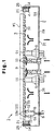
- Fig. 1 is a schematic cross-sectional view showing a hot plate unit according to a first embodiment.
- Fig. 2 is a partial enlarged cross-sectional view showing the hot plate unit of Fig. 1.
- Fig. 3a and 3b are schematic bottom views showing a hot plate according to a further embodiment.
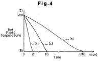
- Fig. 4 is a graph illustrating the cooling speed of the hot plate unit of Fig. 1.
- a hot plate unit 1 according to a first embodiment of the present invention will now be described with reference to Figs. 1 and 2.
- the main elements of the hot plate unit 1 are a metal (e.g., aluminum) casing 2 and a hot plate 3.
- the casing 2 has a bottom wall 2a and an upper opened portion 4.
- Pin insertion sleeves 5, each of which receives a lift pin (not shown), are arranged near the center of the bottom wall 2a at three positions.
- the three lift pins support a silicon wafer W1 and lift the silicon wafer W1 to a predetermined height from the top surface of the hot plate 3.
- a lead wire hole 7 for receiving lead wires 6, which supply current to the hot plate 3, extends through a peripheral portion of the bottom wall 2a.
- the hot plate 3 is a low-temperature hot plate that heats the silicon wafer W, to which a photosensitive resin is applied, to 200 to 300°C and dries the silicon wafer W.
- the hot plate 3 includes a plate-like base material 9, which is made of a sintered ceramic, and heating elements (resistors) 10, which are attached to the plate-like base material 9.
- the plate-like base material 9 is arranged on the upper opened portion 4 with a seal element 14 arranged in between. This defines an internal space S1 within the inner side of the casing 2 and the lower surface of the hot plate 3.
- the plate-like base material 9 is disk-like.
- the diameter of the plate-like base material 9 is slightly smaller than the external dimension of the casing 2.
- the heating elements 10 are concentric or spiral and attached to the lower surface of the plate-like substrate 9.
- Lift pin holes 11 are formed in the central portion of the hot plate 3 at positions corresponding to the three sleeves 5.
- a sintered ceramic nitride which has superior heat resistance and high heat conductivity characteristics, is selected as the material of the plate-like base material 9. It is preferred that the sintered ceramic nitride be a sintered metal nitride, such as aluminum nitride, silicon nitride, boron nitride, and titanium nitride. Sintered aluminum nitride, which has the highest heat conductivity among these sintered substances, is especially preferred.
- a sintered metal carbide ceramic such as silicon carbide, zirconium carbide, titanium carbide, tantalum carbide, and tungsten carbide, may also be used.
- the heating elements 10 are formed by fusing a conductive paste to the plate-like substrate 9.
- the conductive paste includes metal particles, a metal oxide, a resin, and a solvent.
- Preferred metal particles are, for example, gold, silver, platinum, palladium, lead, tungsten, and nickel. These metals are preferred because they withstand oxidation even under high temperatures and because their resistances are such that they are easily heated when energized.
- Preferred metal oxides are, for example, lead oxide, zinc oxide, silica, boron oxide, alumina, yttria, and titania.
- pads 10a which serve as external connection terminals, are formed on two of the ends of the heating elements 10.
- a terminal pin 12 is soldered to each pad 10a.
- Two sockets 6a of the lead wires 6 are fitted to the distal end of the associated terminal pins 12. This electrically connects the terminal pins 12 to the heating elements 10.
- the heating elements 10 are heated when supplied with current via the lead wires 6 and the terminal pins 12 and thereby heat the entire hot plate 3.
- a plurality of equally spaced threaded attachment holes 13 extend through the top surface (lip portion) of the upper opened end portion 4.
- the seal element 14 is arranged on the lip.
- the inner diameter of the annular seal element 14 is substantially equal to the diameter of the upper opened portion 4. It is preferred that the seal element 14 be made of an elastic material, such as resin or rubber.
- the seal element 14 has a plurality of threaded holes 15 corresponding to the plurality of threaded holes 13.
- a stepped support 16 is formed on the inner wall of the seal element 14 to support the lower surface of the hot plate 3. When the hot plate 3 is arranged on the stepped support 16, the top surface of the seal element 14 is flush with the upper surface of the hot plate 3.
- the stepped support 16 supports the hot plate 3 so that it is generally horizontal.
- the seal element 14 seals the space between the top surface of the upper opened portion 4 and the lower surface of the hot plate 3. This prevents fluid (air) from leaking through the space.
- annular holder 21 is fixed to the seal element 14 by bolts 25.
- the annular holder 21 includes a ring 22, a plurality of threaded holes 23, and a plurality of holding tabs 24.
- the holding tabs 24 press the hot plate 3 toward the stepped support 15.
- the hot plate 3 is fixed between the seal element 14 and the annular holder 21.
- two intake ports 17 are fixed to the bottom wall 2a by fasteners, such as bolts.
- the intake ports 17 are arranged near the center of the bottom wall 2a.
- Two lower opened portions 31 extend through the bottom wall 2a. The lower opened portions 31 are located outward in the radial direction from the two intake ports 17. The interior and exterior of the casing 2 are communicated through the intake ports 17.
- a female thread is formed in the lower inner surface of each intake port 17 to receive a fluid supply pipe (not shown).
- the other end of the fluid supply pipe opens at a somewhat distant location from the hot plate unit 1.
- a gas pump is arranged in the fluid supply pump to supply the interior of the casing 2 with cooling air via the intake ports 17.
- a seal packing 8 is fit into the lead wire hole 7.
- the seal packing 8 is an elastic body made of rubber or the like and has a through hole.
- the lead wires 6 are inserted through the through hole of the seal packing 8 and extended out of the casing 2.
- the seal packing 8 seals the space between the lead wires 6 and the lead wire hole 7. This prevents air from flowing through the lead wires 6 and the lead line hole 7.
- the heating elements 10 When the heating elements 10 are energized, the hot plate 3 is heated. The contact between the silicon wafer W1 and the hot plate 3 heats the silicon wafer W1. The heating continues until the photosensitive resin is sufficiently dried. After the drying, the heating elements 10 are de-energized.
- the gas pump is driven to supply the internal space S1 with cooling air through the intake ports 17.
- the cooling air is blown vertically against the lower surface of the hot plate 3 from the intake ports 17.
- the cooling air contacts the entire lower surface of the hot plate 3 and flows toward the lower opened portions 31.
- the flow cools the hot plate in a substantially uniform manner, and the cooling air absorbs the heat of the hot plate 3 and becomes hot.
- the hot air flows through the lower opened portions 31 and is discharged from the hot plate unit 1.
- the thick arrows in Fig. 1 schematically show the flow of the cooling air.
- the cooling efficiency of the hot plate unit 1 of the first embodiment was confirmed as described below. Changes in the surface temperature of the hot plate unit 3 that was heated to 200°C were measured. The time required for the surface temperature to be cooled to 25°C from 200°C (cooling time) was used as a cooling efficiency index. For comparison, the cooling efficiency of two prior art hot plate units was also measured in the same manner. The first prior art hot plate unit did not have a cooling means. The second prior art hot plate unit had a cooling means
- Curve (a) represents the temperature change of the first embodiment.
- Curve (b) represents the temperature change of the first prior art example.
- Curve (c) represents the temperature change of the second prior art example.
- the cooling time was about two minutes in the hot plate unit 1 of the first embodiment. In comparison, the cooling time of the first prior art example was about 240 minutes.
- the cooling time of the second prior art example was about ten minutes. It was thus confirmed that the cooling time of the hot plate unit 1 of the first embodiment was shorter than that of the prior art and that the cooling efficiency was significantly improved.
- the first embodiment has the advantages described below.
- the first embodiment may be modified as described below.
- the seal element 14 may be deleted.
- the hot plate 3 is arranged on the top surface of the upper opening portion 4 of the casing 2, and the annular holder 21 is fastened directly to the casing 2 by screws.
- the number of the intake ports 17 may be increased to three or more. A larger number of the ports 17 uniformly cool the hot plate 3 within a shorter period of time. The number of the lower opened portions 31 may be increased to three or more.
- three separate resistors 32-34 may be employed as the heating elements 10.
- Three heat control circuits are used to heat the resistors 32-34 and independently control the power supplied to the resistors 32-34.
- three heating sections A1 to A3 are defined in the hot plate 3 as shown in Fig. 3b.
- a plurality of (e.g., three) intake ports 17 (marked by o) and lower opened portions 31 (marked by ⁇ ) are arranged in each of the heating sections A1 to A3.
- the three intake ports 17 and the three lower opened portions 31 arranged in the same heating section A1 to A3 are spaced in an equiangular manner.
- the three intake ports 17 and the three lower opened portions 31 in the same section are each located at an apex of a hypothetical equilateral triangle.
- the activation and deactivation of the each control circuit controls the temperature of the associated heating section A1 to A3. Further, the cooling air drawn through the plural intake ports 17 cools each of the heating sections A1 to A3. Thus, the hot plate 3 is uniformly cooled.
- the locations of the intake ports 17 and the lower opened portions 31 may be altered.
- the number of the intake ports 17 and the lower opened portions 31 in the same section may be at least one.
- the number of heat. control circuits may be either two or four or more. In this case, the total number of the intake ports 17 need only be 70 percent or more of the number of heat control circuits, and one or more intake ports 17 need not be provided for each heat control circuit. For example, the number of intake ports 17 may be seven or more when there are ten heat control circuits and three or more when there are four heat control circuits.
- the lead wire hole 7 may be formed in locations other than the bottom wall 2a of the casing 2, such as in the side wall of the casing 2.
- a gas other then air for example, an inert gas such as carbonic acid gas or nitrogen may be circulated as the cooling fluid in the internal space S1.
- an inert gas such as carbonic acid gas or nitrogen
- a fluid that does not affect electric circuits in an undesirable manner such as an insulative liquid, may also be circulated.
- thermocouple may be embedded in the plate-like base material 9 to measure the temperature of the hot plate 3. Based on a detection signal of the thermocouple, the voltage and current provided to the heating element 10 is changed to control the temperature of the hot plate 3. In this case, a lead wire of the thermocouple is extended out of the casing through the seal packing 8.
Landscapes
- Exposure Of Semiconductors, Excluding Electron Or Ion Beam Exposure (AREA)
- Resistance Heating (AREA)
- Surface Heating Bodies (AREA)
Abstract
Description
Claims (6)
- A hot plate unit comprising:a casing having a bottom portion and a first opened portion; anda hot plate arranged in the first opened portion and including a heating element, wherein the bottom portion includes a second opened portion.
- The hot plate unit according to claim 1, further comprising an intake port attached to the casing for enabling the intake of a fluid.
- The hot plate unit according to claim 2, wherein the intake port includes a plurality of intake ports.
- The hot plate unit according to any one of claims 1 to 3, wherein the second opening includes a plurality of second openings.
- The hot plate unit according to any one of claims 2 or 3, wherein the fluid includes air.
- A hot plate unit comprising:a hot plate including a heating element; anda casing for supporting the hot plate, wherein the casing includes a bottom portion facing the hot plate, a first opened portion covered by the hot plate, and a second opened portion formed in the bottom portion.
Applications Claiming Priority (3)
| Application Number | Priority Date | Filing Date | Title |
|---|---|---|---|
| JP22533599 | 1999-08-09 | ||
| JP22533599A JP4330717B2 (en) | 1999-08-09 | 1999-08-09 | Hot plate unit and method of using hot plate unit |
| PCT/JP2000/004785 WO2001011663A1 (en) | 1999-08-09 | 2000-07-17 | Hot plate unit |
Publications (2)
| Publication Number | Publication Date |
|---|---|
| EP1130627A1 true EP1130627A1 (en) | 2001-09-05 |
| EP1130627A4 EP1130627A4 (en) | 2001-11-14 |
Family
ID=16827747
Family Applications (1)
| Application Number | Title | Priority Date | Filing Date |
|---|---|---|---|
| EP00944434A Withdrawn EP1130627A4 (en) | 1999-08-09 | 2000-07-17 | HEATING PLATE ASSEMBLY |
Country Status (5)
| Country | Link |
|---|---|
| EP (1) | EP1130627A4 (en) |
| JP (1) | JP4330717B2 (en) |
| KR (1) | KR100440551B1 (en) |
| CN (1) | CN1147920C (en) |
| WO (1) | WO2001011663A1 (en) |
Families Citing this family (8)
| Publication number | Priority date | Publication date | Assignee | Title |
|---|---|---|---|---|
| TW476983B (en) * | 1999-09-30 | 2002-02-21 | Tokyo Electron Ltd | Heat treatment unit and heat treatment method |
| KR100449687B1 (en) * | 2001-11-22 | 2004-09-22 | 주성엔지니어링(주) | inflow-port assembly for chamber |
| JP2003282403A (en) * | 2002-03-22 | 2003-10-03 | Sumitomo Electric Ind Ltd | Holder for semiconductor manufacturing equipment |
| KR100638584B1 (en) * | 2005-08-01 | 2006-10-27 | 삼성전자주식회사 | Setting method of wafer heater and wafer heater |
| JP4840168B2 (en) * | 2007-01-31 | 2011-12-21 | 東京エレクトロン株式会社 | Heating device, heating method and storage medium |
| KR101365405B1 (en) | 2007-10-12 | 2014-02-19 | 도쿄엘렉트론가부시키가이샤 | Heat treatment apparatus, heat treatment method and storage medium |
| JP5029535B2 (en) * | 2007-10-12 | 2012-09-19 | 東京エレクトロン株式会社 | Heat treatment apparatus, heat treatment method and storage medium |
| KR101780385B1 (en) | 2015-08-31 | 2017-09-21 | 호서대학교 산학협력단 | Oled encapsulation structure and manufacturing method thereof |
Family Cites Families (8)
| Publication number | Priority date | Publication date | Assignee | Title |
|---|---|---|---|---|
| US5223113A (en) * | 1990-07-20 | 1993-06-29 | Tokyo Electron Limited | Apparatus for forming reduced pressure and for processing object |
| USH1145H (en) * | 1990-09-25 | 1993-03-02 | Sematech, Inc. | Rapid temperature response wafer chuck |
| JP2617064B2 (en) * | 1992-07-28 | 1997-06-04 | 日本碍子株式会社 | Semiconductor wafer heating apparatus and method of manufacturing the same |
| EP0628644B1 (en) * | 1993-05-27 | 2003-04-02 | Applied Materials, Inc. | Improvements in or relating to susceptors suitable for use in chemical vapour deposition devices |
| JPH07235588A (en) * | 1994-02-24 | 1995-09-05 | Hitachi Ltd | Wafer chuck and probe inspection method using the same |
| WO1998045875A1 (en) * | 1997-04-07 | 1998-10-15 | Komatsu Ltd. | Temperature control device |
| KR100316711B1 (en) * | 1999-06-14 | 2001-12-12 | 윤종용 | A electro-static chuck improved in temperature control performance |
| KR200243530Y1 (en) * | 1999-06-30 | 2001-09-29 | 이영원 | Bake apparatus for semiconductive wafer |
-
1999
- 1999-08-09 JP JP22533599A patent/JP4330717B2/en not_active Expired - Lifetime
-
2000
- 2000-07-17 EP EP00944434A patent/EP1130627A4/en not_active Withdrawn
- 2000-07-17 CN CNB008016283A patent/CN1147920C/en not_active Expired - Lifetime
- 2000-07-17 WO PCT/JP2000/004785 patent/WO2001011663A1/en not_active Ceased
- 2000-07-17 KR KR10-2001-7004221A patent/KR100440551B1/en not_active Expired - Fee Related
Also Published As
| Publication number | Publication date |
|---|---|
| CN1319251A (en) | 2001-10-24 |
| EP1130627A4 (en) | 2001-11-14 |
| KR20010089288A (en) | 2001-09-29 |
| WO2001011663A1 (en) | 2001-02-15 |
| CN1147920C (en) | 2004-04-28 |
| KR100440551B1 (en) | 2004-07-15 |
| JP2001052985A (en) | 2001-02-23 |
| JP4330717B2 (en) | 2009-09-16 |
Similar Documents
| Publication | Publication Date | Title |
|---|---|---|
| US6639191B2 (en) | Hot plate unit | |
| US6686570B2 (en) | Hot plate unit | |
| CN1147920C (en) | Orifice plate mechanism | |
| US20040226935A1 (en) | Hot plate unit | |
| JP3588457B2 (en) | Wafer heating device | |
| JP2003077779A (en) | Wafer heating device | |
| US20020155262A1 (en) | Ceramic heater | |
| JP3313698B2 (en) | Hot plate unit for semiconductor manufacturing equipment | |
| JP3373197B2 (en) | Hot plate unit for semiconductor manufacturing equipment | |
| JP2002198297A (en) | Wafer heating device | |
| JP3348712B2 (en) | Hot plate unit | |
| JP3532166B2 (en) | Hot plate unit | |
| JP4180453B2 (en) | Hot plate unit | |
| JP2001189276A (en) | Wafer heating device | |
| JP3500119B2 (en) | Hot plate unit for semiconductor manufacturing equipment | |
| JP2003297531A (en) | Ceramic temperature controller and ceramic temperature controller | |
| JP2001052985A5 (en) | How to use the hot plate unit and hot plate unit | |
| JP3497463B2 (en) | Hot plate unit for semiconductor manufacturing equipment | |
| EP1079416A1 (en) | Hot plate unit | |
| JP2003178964A (en) | Hot plate unit | |
| JP3872260B2 (en) | Wafer heating device | |
| JP2004095689A (en) | Wafer heating device | |
| JP5966959B2 (en) | Semiconductor inspection method | |
| WO2001011664A1 (en) | Support container and semiconductor manufacturing/inspecting device | |
| JP2004031099A (en) | Wafer heating device |
Legal Events
| Date | Code | Title | Description |
|---|---|---|---|
| PUAI | Public reference made under article 153(3) epc to a published international application that has entered the european phase |
Free format text: ORIGINAL CODE: 0009012 |
|
| 17P | Request for examination filed |
Effective date: 20010410 |
|
| AK | Designated contracting states |
Kind code of ref document: A1 Designated state(s): AT BE CH CY DE DK ES FI FR GB GR IE IT LI LU MC NL PT SE |
|
| AX | Request for extension of the european patent |
Free format text: AL;LT;LV;MK;RO;SI |
|
| A4 | Supplementary search report drawn up and despatched |
Effective date: 20010928 |
|
| AK | Designated contracting states |
Kind code of ref document: A4 Designated state(s): AT BE CH CY DE DK ES FI FR GB GR IE IT LI LU MC NL PT SE |
|
| RIC1 | Information provided on ipc code assigned before grant |
Free format text: 7H 01L 21/00 A |
|
| 17Q | First examination report despatched |
Effective date: 20030924 |
|
| STAA | Information on the status of an ep patent application or granted ep patent |
Free format text: STATUS: THE APPLICATION IS DEEMED TO BE WITHDRAWN |
|
| 18D | Application deemed to be withdrawn |
Effective date: 20050831 |