EP1130285A1 - Toroidal-type continuously variable transmission - Google Patents
Toroidal-type continuously variable transmission Download PDFInfo
- Publication number
- EP1130285A1 EP1130285A1 EP01105029A EP01105029A EP1130285A1 EP 1130285 A1 EP1130285 A1 EP 1130285A1 EP 01105029 A EP01105029 A EP 01105029A EP 01105029 A EP01105029 A EP 01105029A EP 1130285 A1 EP1130285 A1 EP 1130285A1
- Authority
- EP
- European Patent Office
- Prior art keywords
- support plate
- plate portion
- toroidal
- portions
- continuously variable
- Prior art date
- Legal status (The legal status is an assumption and is not a legal conclusion. Google has not performed a legal analysis and makes no representation as to the accuracy of the status listed.)
- Granted
Links
- 230000005540 biological transmission Effects 0.000 title claims abstract description 43
- 238000005096 rolling process Methods 0.000 claims description 31
- 230000005489 elastic deformation Effects 0.000 description 10
- 230000002093 peripheral effect Effects 0.000 description 7
- 230000033001 locomotion Effects 0.000 description 5
- 230000001133 acceleration Effects 0.000 description 3
- 238000005452 bending Methods 0.000 description 2
- 238000005516 engineering process Methods 0.000 description 2
- 230000005484 gravity Effects 0.000 description 2
- 239000003921 oil Substances 0.000 description 2
- 230000007423 decrease Effects 0.000 description 1
- 230000003247 decreasing effect Effects 0.000 description 1
- 230000000694 effects Effects 0.000 description 1
- 230000013011 mating Effects 0.000 description 1
- 238000000034 method Methods 0.000 description 1
- 239000010689 synthetic lubricating oil Substances 0.000 description 1
Images




Classifications
-
- F—MECHANICAL ENGINEERING; LIGHTING; HEATING; WEAPONS; BLASTING
- F16—ENGINEERING ELEMENTS AND UNITS; GENERAL MEASURES FOR PRODUCING AND MAINTAINING EFFECTIVE FUNCTIONING OF MACHINES OR INSTALLATIONS; THERMAL INSULATION IN GENERAL
- F16H—GEARING
- F16H15/00—Gearings for conveying rotary motion with variable gear ratio, or for reversing rotary motion, by friction between rotary members
- F16H15/02—Gearings for conveying rotary motion with variable gear ratio, or for reversing rotary motion, by friction between rotary members without members having orbital motion
- F16H15/04—Gearings providing a continuous range of gear ratios
- F16H15/06—Gearings providing a continuous range of gear ratios in which a member A of uniform effective diameter mounted on a shaft may co-operate with different parts of a member B
- F16H15/32—Gearings providing a continuous range of gear ratios in which a member A of uniform effective diameter mounted on a shaft may co-operate with different parts of a member B in which the member B has a curved friction surface formed as a surface of a body of revolution generated by a curve which is neither a circular arc centered on its axis of revolution nor a straight line
- F16H15/36—Gearings providing a continuous range of gear ratios in which a member A of uniform effective diameter mounted on a shaft may co-operate with different parts of a member B in which the member B has a curved friction surface formed as a surface of a body of revolution generated by a curve which is neither a circular arc centered on its axis of revolution nor a straight line with concave friction surface, e.g. a hollow toroid surface
- F16H15/38—Gearings providing a continuous range of gear ratios in which a member A of uniform effective diameter mounted on a shaft may co-operate with different parts of a member B in which the member B has a curved friction surface formed as a surface of a body of revolution generated by a curve which is neither a circular arc centered on its axis of revolution nor a straight line with concave friction surface, e.g. a hollow toroid surface with two members B having hollow toroid surfaces opposite to each other, the member or members A being adjustably mounted between the surfaces
Definitions
- the present invention relates to a toroidal-type continuously variable transmission which is used as a transmission unit in an automatic transmission for a car or as a transmission for various kinds of industrial machines.
- a transmission for a car in some cases, there is used such a toroidal-type continuously variable transmission as shown in Figs. 3 and 4.
- this toroidal-type continuously variable transmission for example, as disclosed in Japanese Unexamined Utility model Publication No. Sho. 62-71465 (JP-62-71465U), an input side disk 2 serving as a first disk is supported concentrically with an input shaft 1 and, to the end portion of an output shaft 3 which is disposed concentrically with the input shaft 1, there is fixed an output side disk 4 which is used as a second disk.
- trunnions 6, 6 which can be respectively swung about their associated pivot shafts 5, 5, while the pivot shafts 5, 5 are arranged at positions which are twisted with respect to the input and output shafts 1 and 3.
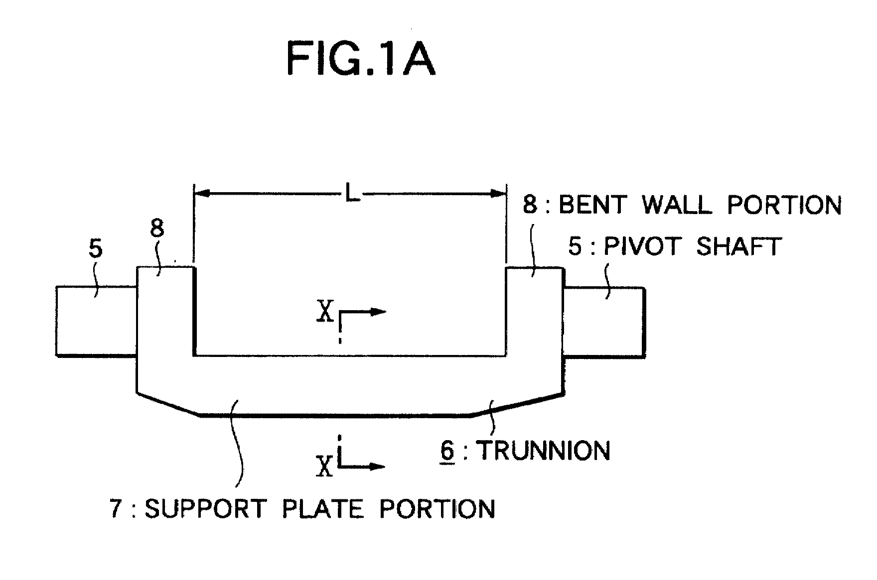
- each trunnion 6 includes a support plate portion 7 and, as shown in Fig. 5, in the two end portions of the support plate portion 7 in the longitudinal direction thereof (in Fig. 5, in the right and left direction) , there are formed a pair of bent wall portions 8, 8 in such a manner that they are bent toward the inner surface side (in Fig. 5, the lower side) of the support plate portion 7.
- the pivot shafts 5, 5 are respectively disposed on the outer surfaces of the bent wall portions 8, 8 (the surfaces of the bent wall portions 8, 8 that are present on the opposite side to the support plate portion 7) in such a manner that the pivot shafts 5, 5 are concentric with each other.
- a circular hole 10 which is used to support the base half portion of a shift shaft 9 to be discussed below.
- the input side and output side disks 2, 4 respectively include inner surfaces 2a, 4a which are opposed to each other; and, the section of each of the inner surfaces 2a, 4a is formed as a concave surface which can be obtained by rotating an arc with the pivot shaft 5 as a center thereof or a curved line close to such arc. And, the peripheral surface 11a, 11a, each of which is formed as a spherically convex-shaped surface, of the power rollers 11, 11 are contacted with the inner surfaces 2a, 4a, respectively.
- the pressure device 12 is composed of a cam plate 13 rotatable together with the input shaft 1, and a plurality of (for example, four) rollers 15, 15 respectively held by a retainer 14, And, on one side surface (in Figs. 3 and 4, the left side surface) of the cam plate 13, there is formed a cam surface 15 consisting of an uneven (concave- and convex-shaped) surface which extends in the circumferential direction of the cam plate 13; and, on the outer surface (in Figs.
- the rotation speeds of the input and output shafts 1 and 3 can be changed in two manners. Firstly, to carry out deceleration between the input and output shafts 1 and 3, the trunnions 6, 6 may be respectively swung about their associated pivot shafts 5, 5 to thereby incline the respective shift shafts 9, 9 in such a manner that, as shown in Fig. 3, the peripheral surfaces 11a, 11a of the power rollers 11, 11 can be respectively contacted with the near-center portion of the inner surface 2a of the input side disk 2 and the near-outer-periphery portion of the inner surface 4a of the output side disk 4.
- the trunnions 6, 6 may be respectively swung about to thereby incline the respective shift shafts 9, 9 in such a manner that, as shown in Fig. 4, the peripheral surfaces lla, lla of the power rollers 11, 11 can be respectively contacted with the near-outer-periphery portion of the inner surface 2a of the input side disk 2 and the near-center portion of the inner surface 4a of the output side disk 4.
- the inclination angles of the shift shafts 9, 9 are set between the angles shown in Figs. 3 and 4
- an intermediate transmission ratio can be obtained between the input and output shafts 1 and 3.
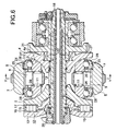
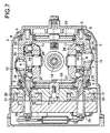
- Figs. 6 and 7 respectively show a more specific conventional toroidal-type continuously variable transmission which is disclosed in Japanese Utility Model Unexamined publication No. Hei 1-173552 (JP-1-173552U) that is filed and stored in a microfilm.
- input side and output side disks 2 and 4 are supported respectively through their associated needle roller bearings 19 and 19 on the periphery of a circular-pipe-shaped input shaft 18 in such a manner that they can be rotated as well as can be shifted in the axial direction thereof.
- a cam plate 13 which is used to form a pressure device 12 of a loading cam type, is spline-engaged with the outer peripheral surface of the end portion (in Fig.
- an output gear 21 is connected to the output side disk 4 by keys 22 and 22, so that the output side disk 4 and output gear 21 can be rotated in synchronization with each other.
- a pair of trunnions 6 and 6 each of which has such a structure as shown in Fig. 5, are respectively supported on a pair of support plates 23 and 23 in such a manner that they can be swung as well as can be shifted in the axial direction thereof (in Fig. 6, in the front and back direction; and, in Fig. 7, in the right and left direction).
- a pair of shift shafts 9 each including a base half portion and a leading half portion which are formed in such a manner that they are parallel but eccentric with respect to each other.
- each shift shaft 9 is rotatably supported in a circular hole 10 portion formed in the intermediate portion of each of two support plate portions 7 and 7 which respectively form their associated trunnions 6 and 6. Also, in the peripheries of the leading half portions of the shift shafts 9 that project from the inner surfaces of the support plate portions 7, there are respectively supported power rollers 11 in such a manner that they can be rotated.
- the pair of shift shafts 9 and 9 respectively disposed on the pair of trunnions 6 and 6 are located at positions which are present on the 180° opposite side with respect to the input shaft 18.
- the directions, in which the leading half portions of the shift shafts 9 and 9 are eccentric with respect to the base half portions thereof are set the same direction (in Fig. 7, the reversed right arid left directions) with respect to the rotation direction of the input side and output side disks 2 and 4.
- the eccentric direction is set as a direction extending almost at right angles to the arranging direction (axial direction) of the input shaft 18. Therefore, the power rollers 11 and 11 are supported in such a manner that they can be slightly shifted in the arranging direction of the input shaft 18.
- thrust ball bearings 24 which are thrust rolling bearings, and thrust needle roller bearings 25 in the order that starts from the outer surfaces of the power rollers 11.
- the thrust ball bearings 24 carry the thrust-direction loads that are applied to the power rollers 11 as well as permit the rotating motion of the power rollers 11.
- Each of the thrust ball bearings 24 is composed of a plurality of balls 26, 26, a circular-ring-shaped retainer 27 for holding these balls 26, 26 in such a manner that the balls 26, 26 can be rotated, and a circular-ring-shaped outer race 28.
- the inner race raceway of each thrust ball bearing 24 is formed on the outer surface of the power roller 11, whereas the outer race raceway thereof is formed on the inner surface of each outer race 28.
- the thrust needle roller bearings 25 are held by and between the inner surfaces of the support plate portions 7 forming the trunnions 6, 6 and the outer surfaces of the outer races 28, respectively.
- two drive rods 29 are respectively coupled to the one-side end portions (in Fig. 7, the left end portions) of their associated trunnions 6, 6; and, two drive pistons 30 are respectively fixed to the outer peripheral surfaces of the intermediate portions of the drive rods 29. And, the drive pistons 30 are fitted into their associated drive cylinders 31 in an oil-tight manner.
- the pair of drive pistons 30 and 30 may be shifted in the mutually opposite directions.
- the pair of trunnions. 6 and 6 are shifted in the mutually.opposite directions, whereby, for example, the power roller 11 shown on the lower side in Fig. 7 is shifted to the right in Fig. 7, whereas the power roller 11 shown on the upper side in Fig. 7 is shifted to the left in Fig. 7.
- This changes the direction of the tangential-direction force that is applied to the contact portions between the peripheral surfaces lla, 11a of the power rollers 11, 11 and the inner surfaces 2a, 4a of the input side and output side disks 2, 4.
- the trunnions 6, 6 are swung in the mutually opposite directions about their associated pivot shafts 5, 5 that are pivotally supported on their associated support plates 23, 23.
- the thrust needle roller bearings 25 are present between the outer surfaces of the outer races 28 and the inner surfaces of the support plate portions 7 forming the trunnions 6, the rotational movement of the power rollers 11 and outer races 28 can be carried out smoothly. This can reduce the force that is necessary to change the inclination angles of the shift shafts 9, 9.
- the thrust loads which are applied to the balls 26, 26 used as the rolling bodies forming the thrust ball bearings 24 as well as to the needle rollers forming the'thrust needle' roller bearings 25, are made to vary unevenly. That is, as the result of the great elastic deformation of the trunnions 6, the distance between the inner surfaces of the trunnions 6 and the outer surfaces of the power rollers 11 are made to vary unevenly. This uneven variation in the distance decreases the thrust load to be applied to the rolling bodies existing in the portion where the distance between these inner and outer surfaces is increased, but it increases the thrust load to be applied to the rolling bodies existing in the portion where the distance between these inner and outer surfaces is decreased.
- JP-A-7-229546 Japanese Patent Unexamined Publication No. Hei. 7-229546
- the section shape of the support plate portion 7 forming the trunnion 6 is formed as an isosceles trapezoid where its inner surface side (in Fig. 8, upper side) is set as a long side and its outer surface side (in Fig. 8, lower side) is set as a short side.
- the length dimension of the long side on the outer surface side is set as 2R
- the length dimension of the short side on the inner surface side is set as 2 x R/ ⁇ ,3 and the distance between the long and short sides, that is, the length of a line connecting these two sides is set as ⁇ (2/3) x R.
- the support plate portion 7 which has a section having an isosceles trapezoid shape
- its section coefficient Z is 0.188 x R 3 and its section area S is 1.29 R 2 .
- a ratio of the section coefficient Z to the section area S that is, Z/S is 0.146R.
- This numeric value (0.146R) is larger than a case where the section of a support plate portion has a semicircular or rectangular shape. Therefore, in the case of the support plate portion 7 having such a section shape as shown in Fig. 7, although its section area is relatively small, in other words, although the support plate portion 7 is relatively light in weight, there can be obtained a sufficient section coefficient, which makes it possible to realize a trunnion 6 which is large in bending rigidity.
- the thickness of the outer race 28 in the axial direction thereof cannot be increased so much when it is desired to reduce the weight of the outer race 28. Therefore, when the toroidal-type continuously variable transmission is in operation, the outer race 28 tends to be elastically deformed unevenly with respect to the circumferential direction thereof. As a result of this, depending on the rigidity of the support plate portion 7, there is a fear that the contact pressure between the rolling surfaces of the specific balls 26, 26 and their mating raceways can be increased excessively. Description will be given below of this fear with reference to Fig. 2. By the way, Figs.
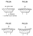
- FIGS. 2A to 2D typically show the relation between the support plate portion 7 of the trunnion 6 and the outer race 28 forming the thrust ball bearing 24, while there is omitted therefrom the thrust needle roller bearing 25 (Figs. 6 and 7) existing between these two members 7 and 28.
- the above-mentioned elastic deformation of the support plate portion 7 and outer race 28 must be checked not only in the width direction of the support plate portion 7 but also in the longitudinal direction thereof. That is, when the toroidal-type continuously variable transmission is in operation, the support plate portion 7, as shown by a chained line in the figure 5 that has been discussed before, is deformed elastically in a direction where the longitudinal-direction central portion of the inner surface of the support plate portion 7 provides a concave-shaped surface. Therefore, in order to be able to make even the surface pressures of the contact portions between the rolling surfaces of the balls 26, 26 and their associated raceways, the elastic deformation of the support plate portion 7 in the longitudinal direction thereof must also be taken into account.
- the present invention aims at eliminating the drawbacks found in the above-mentioned conventional toroidal-type continuously variable transmissions. Accordingly, it is an object of the invention to provide a toroidal-type continuously variable transmission in which the relation between the section shape of a support plate portion forming a trunnion and the length thereof is specified, and the support plate portion is elastically deformed in a proper manner to thereby make as even as possible the surface pressures of the contact portions between the rolling surfaces of the respective balls 26, 26 forming the thrust ball bearing 24 and their associated raceways.
- a toroidal-type continuously variable transmission comprising: first and second disks supported rotatably and concentrically with each other, with their respective inner surfaces disposed opposed to each other; trunnions respectively swingable about their associated pivot shafts respectively disposed at positions which is twisted with respect to the center axes of the first and second disks; shift shafts respectively supported in the intermediate portions of support plate portions respectively forming their associated trunnions in such a manner that they respectively project from the respective inner surfaces of the support plate portions; power rollers respectively held by and between the first and second disks in such a manner that they are rotatably supported on the peripheries of their associated shift shafts; and, thrust rolling bearings respectively disposed on the outer surfaces of their associated power rollers for permitting the power rollers to rotate while supporting thrusts-direction loads applied to the power rollers.
- each of the trunnions is structured in the following manner: that is, a pair of bent wall portions are respectively formed in the longitudinal-direction two end portions of the support plate portion in such a manner that they are bent toward the inner surface side of the support plate portion; and, the pivot shafts are respectively disposed on the outer surfaces of the pair of bent wall portions in such a manner that they are concentric with each other.
- the section area of the support plate portion is expressed as S
- the length of the portion of the support plate portion that exists between the respective inner surfaces of the pair of bent wall portions. is expressed as L
- the section coefficient of the support plate portion is expressed as Z
- the ratio (S x L) / Z is specified in the range of 10 - 35 (more preferably, in the range of 15 - 30).
- the ratio (S x L) / Z of the product S x L of the section area S of the support plate portion forming its associated trunnion and the length L of the support plate portion to the section coefficient Z of the support plate portion is specified in the proper range, thereby being able to secure the rolling fatigue lives of the component members of the thrust rolling bearing which is used to allow the rotational movement of the power roller.
- the support plate portion can be elastically deformed according to the thrust load that is applied to the outer race forming the thrust rolling bearing.
- This can prevent the respective rolling bodies from varying greatly from each other in the surface pressure of the contact portion thereof with respect to the inner race raceway formed on the outer surface of the power roller and the outer race raceway formed on the inner surface of the outer race. This makes it possible to secure the rolling fatigue lives of the respective rolling bodies as well as the inner race raceway and outer race raceway.
- a section of the support plate portion in a width direction is bent in a concave manner so that end portions in the width direction are bent away from an inner surface side of the support plate portion. Therefore, the durability of the thrust ball bearing 24 can be secured sufficiently.
- the shape and dimension of the support plate portion 7 forming the trunnion 6 to be incorporated into a toroidal-type continuously variable transmission are improved to thereby be able to secure the rolling fatigue lives of the component members of the thrust ball bearing 24 (see Figs. 6 and 7) interposed between the inner surface of the support plate portion 7 and power roller 11.
- the structures and operations of the other remaining portions of the invention are similar to the conventional structures including, for example, the structure shown in the above-mentioned figures 6 and 7. Therefore, the duplicate illustration and description thereof are omitted here and thus description will be given below mainly of the characteristic portions of the invention.
- a pair of bent wall portions 8, 8 in such a manner that they are respectively bent toward the inner surface side (in Fig. 1A, the upper side) of the support plate portion 7.
- pivot shafts 5, 5 on the respective outer surfaces of the two bent wall portions 8, 8, there are disposed pivot shafts 5, 5 in such a manner that they are concentric with each other.
- the shape of the section of the support plate portion 7 is formed as an isosceles trapezoid in which its inner surface side (in Fig.
- Test conditions are as follows: Rotation speed of the input shaft 18 4000min -1 (r.p.m.) Input torque 370N m ( ⁇ 3.7.8kg m) Oil used Synthetic lubricating oil Oil temperature 100° .
- a toroidal-type continuously variable transmission used to transmit such large torque as mentioned above is generally a toroidal-type continuously variable transmission of a double cavity type in which input side and output side disks are arranged by twos each and in parallel to each other in the power transmission direction.
- results obtained in the test that was conducted in these conditions are shown in the next table 3.
- the test was completed at the time of the passage of one hundred hours.
- the life time of 100 hours or more shows that no damage was found in the component members of the thrust ball bearing 24 at the test end time.
- the term "outer race flaking” shows that a flaking phenomenon occurred in an outer race raceway formed on the inner surface of an outer race 28 forming the thrust ball bearing 24.
- reference characters B to D which are used to express the deformed states of the outer race 28, show that the elastically deformed state of the outer race 28 and the support plate portion 7 of the trunnion 6 corresponds to any one of the states shown in the above-mentioned figures 2B to 2D.
- Table 3 shows the results of the test conducted under the above conditions and, from Table 3, there can be found the following facts.
- the support plate portion 7 of the trunnion 6 backing up the outer race 28 forming the thrust ball bearing 24, as shown in Fig. 2C, is deformed in the same direction as the direction of the elastic deformation of the power roller 11 that occurs when a toroidal-type continuously variable transmission is in operation.
- the ratio (S x L) / Z of the product S x L of the section area S and length L to the section coefficient Z is reduced slightly (10.0) and thus, as shown in Fig. 2B, there is found a tendency that only the outer race 28 forming the thrust ball bearing 24 is elastically deformed.
- the support plate portion 7 is elastically deformed to a slight degree. Therefore, the load distribution of the plurality of balls 26, 26 forming the thrust ball bearing 24 becomes rather uneven. As a result of this, at the time of 84 hours, there occurred a flaking phenomenon in the outer race raceway that is formed on the inner surface of the outer race 28.
- the life of the thrust ball bearing 24 is enhanced three times or more. This shows that, in case where the above ratio (S x L) / Z is specified in the range of 10 - 35, the life of the thrust ball bearing 24 can be extended over the conventional thrust ball bearing 24.
- the support plate portion 7 forming the trunnion 6, as shown in Fig. 2D is easy to deform elastically in a direction where the width-direction central portion of the inner surface of the support plate portion 7 provides a concave-shaped surface and the elastic deformation amount thereof is large.
- a toroidal-type continuously variable transmission according to the invention is structured and can be operated in the above-mentioned manner, according to the invention, there can be realized a toroidal-type continuously variable transmission which is light in weight and excellent in durability.
Landscapes
- Engineering & Computer Science (AREA)
- General Engineering & Computer Science (AREA)
- Mechanical Engineering (AREA)
- Friction Gearing (AREA)
Abstract
Description
- The present invention relates to a toroidal-type continuously variable transmission which is used as a transmission unit in an automatic transmission for a car or as a transmission for various kinds of industrial machines.
- As a transmission for a car, in some cases, there is used such a toroidal-type continuously variable transmission as shown in Figs. 3 and 4. In this toroidal-type continuously variable transmission, for example, as disclosed in Japanese Unexamined Utility model Publication No. Sho. 62-71465 (JP-62-71465U), an
input side disk 2 serving as a first disk is supported concentrically with aninput shaft 1 and, to the end portion of anoutput shaft 3 which is disposed concentrically with theinput shaft 1, there is fixed anoutput side disk 4 which is used as a second disk. In the interior portion of a casing in which the toroidal-type continuously variable transmission is stored, there are disposedtrunnions pivot shafts pivot shafts output shafts - That is, each
trunnion 6 includes asupport plate portion 7 and, as shown in Fig. 5, in the two end portions of thesupport plate portion 7 in the longitudinal direction thereof (in Fig. 5, in the right and left direction) , there are formed a pair ofbent wall portions support plate portion 7. And, thepivot shafts bent wall portions 8, 8 (the surfaces of thebent wall portions support plate portion 7, there is formed acircular hole 10 which is used to support the base half portion of ashift shaft 9 to be discussed below. - In the
circular hole 10 formed in the intermediate portion of thesupport plate portion 7 which forms eachtrunnion 6 having the above structure, there is supported the base half portion of theshift shaft 9. And, by swinging therespective trunnions pivot shafts shift shafts 9 supported in the intermediate portions of thetrunnions shift shafts 9 with their respective base half portions supported in their associatedtrunnions shift shafts 9 that are projected from the inner surfaces of thetrunnions power rollers 11 in such a manner that they can be rotated. And, thepower rollers 11 are held by and between the input side andoutput side disks - The input side and
output side disks inner surfaces inner surfaces pivot shaft 5 as a center thereof or a curved line close to such arc. And, theperipheral surface power rollers inner surfaces - Between the
input shaft 1 andinput side disk 2, there is interposed apressure device 12 of a loading cam type; and, theinput side disk 2 is elastically pushed toward theoutside disk 4 by thepressure device 12. Thepressure device 12 is composed of acam plate 13 rotatable together with theinput shaft 1, and a plurality of (for example, four)rollers retainer 14, And, on one side surface (in Figs. 3 and 4, the left side surface) of thecam plate 13, there is formed acam surface 15 consisting of an uneven (concave- and convex-shaped) surface which extends in the circumferential direction of thecam plate 13; and, on the outer surface (in Figs. 3 and 4, the right side surface) of theinput disk 2 as well, there is formed asimilar cam surface 17. Also, the plurality ofrollers input shaft 1. - When the above-structured toroidal-type continuously variable transmission is in use, in case where the
cam plate 13 is rotated as theinput shaft 1 is rotated, thecam surface 16 presses the plurality ofrollers cam surface 17 formed on the outer surface of theinput side disk 2. As a result of this, not only theinput side disk 2 is pressed against the plurality ofpower rollers cam surface rollers input side disk 2 is rotated. And, the rotational movement of theinput side disk 2 is transmitted through thepower rollers output side disk 4, thereby rotating theoutput shaft 3 which is fixed to theoutput side disk 4. - Now, the rotation speeds of the input and
output shafts output shafts trunnions pivot shafts respective shift shafts peripheral surfaces power rollers inner surface 2a of theinput side disk 2 and the near-outer-periphery portion of theinner surface 4a of theoutput side disk 4. - On the other hand, to carry out acceleration between the input and
output shafts trunnions respective shift shafts power rollers inner surface 2a of theinput side disk 2 and the near-center portion of theinner surface 4a of theoutput side disk 4. By the way, in case where the inclination angles of theshift shafts output shafts - Further, Figs. 6 and 7 respectively show a more specific conventional toroidal-type continuously variable transmission which is disclosed in Japanese Utility Model Unexamined publication No. Hei 1-173552 (JP-1-173552U) that is filed and stored in a microfilm. In this transmission, input side and
output side disks needle roller bearings shaped input shaft 18 in such a manner that they can be rotated as well as can be shifted in the axial direction thereof. Also, acam plate 13, which is used to form apressure device 12 of a loading cam type, is spline-engaged with the outer peripheral surface of the end portion (in Fig. 6, the left end portion) of theinput shaft 18; and, acollar portion 20 prevents thecam plate 13 from moving in a direction to part away from theinput side disk 2. Further, anoutput gear 21 is connected to theoutput side disk 4 bykeys output side disk 4 andoutput gear 21 can be rotated in synchronization with each other. - The two end portions of a pair of
trunnions support plates shift shafts 9 each including a base half portion and a leading half portion which are formed in such a manner that they are parallel but eccentric with respect to each other. The base half section of eachshift shaft 9 is rotatably supported in acircular hole 10 portion formed in the intermediate portion of each of twosupport plate portions trunnions shift shafts 9 that project from the inner surfaces of thesupport plate portions 7, there are respectively supportedpower rollers 11 in such a manner that they can be rotated. - By the way, the pair of
shift shafts trunnions input shaft 18.. Also, the directions, in which the leading half portions of theshift shafts output side disks input shaft 18. Therefore, thepower rollers input shaft 18. As a result of this, even in case where thepower rollers input shaft 18 because the component members are elastically deformed due to the thrust load that is generated by thepressure device 12, the shifting amounts of the power rollers can be absorbed without applying an unreasonable force to the respective component members. - Also, between the outer surfaces of the
power rollers support plate portions 7 forming thetrunnions thrust ball bearings 24, which are thrust rolling bearings, and thrustneedle roller bearings 25 in the order that starts from the outer surfaces of thepower rollers 11. Of the two kinds of bearings, thethrust ball bearings 24 carry the thrust-direction loads that are applied to thepower rollers 11 as well as permit the rotating motion of thepower rollers 11. Each of thethrust ball bearings 24 is composed of a plurality ofballs shaped retainer 27 for holding theseballs balls outer race 28. Also, the inner race raceway of each thrust ball bearing 24 is formed on the outer surface of thepower roller 11, whereas the outer race raceway thereof is formed on the inner surface of eachouter race 28. - Also, the thrust
needle roller bearings 25 are held by and between the inner surfaces of thesupport plate portions 7 forming thetrunnions outer races 28, respectively. The thus structured thrust-needle roller bearings 25, while carrying the thrust loads that are applied to theouter races 28 from thepower rollers 11, permit thepower rollers 11 andouter races 28 to swing and shift about the base half portions of their associatedshift shafts 9. - Further, two
drive rods 29 are respectively coupled to the one-side end portions (in Fig. 7, the left end portions) of their associatedtrunnions drive pistons 30 are respectively fixed to the outer peripheral surfaces of the intermediate portions of thedrive rods 29. And, thedrive pistons 30 are fitted into their associateddrive cylinders 31 in an oil-tight manner. - In the case of the above-structured toroidal-type continuously variable transmission, the rotational movement of the
input shaft 18 is transmitted through thepressure device 12 to theinput side disk 2. And, the rotation of theinput side disk 2 is transmitted through the pair ofpower'rollers output side disk 4, while the rotation of theoutput side disk 4 is then taken out by theoutput gear 21. - To change a rotation speed ratio between the
input shaft 18 andoutput gear 21, the pair ofdrive pistons drive pistons 30 are shifted, the pair of trunnions. 6 and 6 are shifted in the mutually.opposite directions, whereby, for example, thepower roller 11 shown on the lower side in Fig. 7 is shifted to the right in Fig. 7, whereas thepower roller 11 shown on the upper side in Fig. 7 is shifted to the left in Fig. 7. This changes the direction of the tangential-direction force that is applied to the contact portions between the peripheral surfaces lla, 11a of thepower rollers inner surfaces output side disks trunnions pivot shafts support plates - As a result of this, as has been previously shown in Figs. 3 and 4, the contact positions between the
peripheral surfaces power rollers inner surfaces output side disks input shaft 18 andoutput gear 21 is changed. In this manner, in case where a torque to be transmitted between theinput shaft 18 andoutput gear 21 is caused to vary and the amounts of the elastic deformation of the respective component members are caused to vary, thepower rollers outer races 28 attached to thesepower rollers 11 are slightly rotated about the base half portions of their associatedshift shafts 9. Because the thrustneedle roller bearings 25 are present between the outer surfaces of theouter races 28 and the inner surfaces of thesupport plate portions 7 forming thetrunnions 6, the rotational movement of thepower rollers 11 andouter races 28 can be carried out smoothly. This can reduce the force that is necessary to change the inclination angles of theshift shafts - When the above-structured toroidal-type continuously variable transmission is in operation, to the
power rollers 11 that are rotatably supported on the inner surface side of their associatedtrunnions inner surfaces output side disks thrust ball bearings 24 and thrustneedle roller bearings 25 to the inner surfaces of thesupport plate portions 7 respectively forming their associatedtrunnions 6. Therefore, when the toroidal-type continuously variable transmission is in operation, as exaggeratedly shown by chained lines in Fig. 5, thetrunnions - And, in case where the amount of such elastic deformation increases, the thrust loads, which are applied to the
balls thrust ball bearings 24 as well as to the needle rollers forming the'thrust needle'roller bearings 25, are made to vary unevenly. That is, as the result of the great elastic deformation of thetrunnions 6, the distance between the inner surfaces of thetrunnions 6 and the outer surfaces of thepower rollers 11 are made to vary unevenly. This uneven variation in the distance decreases the thrust load to be applied to the rolling bodies existing in the portion where the distance between these inner and outer surfaces is increased, but it increases the thrust load to be applied to the rolling bodies existing in the portion where the distance between these inner and outer surfaces is decreased. As a result of this, an excessive thrust load is applied to the specific ones of the rolling bodies, which increases excessively the contact pressure between such specific rolling bodies and the raceways in contact with the rolling surfaces of such specific rolling bodies. This results in the extremely shortened fatigue lives of the specific rolling surfaces and the raceways in contact therewith. - In order to prevent the shortened fatigue lives of the rolling surfaces of the specific rolling bodies and the raceways in contact therewith caused by the above excessive thrust load, in Japanese Patent Unexamined Publication No. Hei. 7-229546 (JP-A-7-229546), there is disclosed a technology in which, as shown in Fig. 8, the section shape of the
support plate portion 7 forming thetrunnion 6 is formed as an isosceles trapezoid where its inner surface side (in Fig. 8, upper side) is set as a long side and its outer surface side (in Fig. 8, lower side) is set as a short side. And, in case where the length dimension of the long side on the outer surface side is set as 2R, the length dimension of the short side on the inner surface side is set as 2 x R/√,3 and the distance between the long and short sides, that is, the length of a line connecting these two sides is set as √ (2/3) x R. - In the case of the
support plate portion 7 which has a section having an isosceles trapezoid shape, its section coefficient Z is 0.188 x R3 and its section area S is 1.29 R2. And, a ratio of the section coefficient Z to the section area S, that is, Z/S is 0.146R. This numeric value (0.146R) is larger than a case where the section of a support plate portion has a semicircular or rectangular shape. Therefore, in the case of thesupport plate portion 7 having such a section shape as shown in Fig. 7, although its section area is relatively small, in other words, although thesupport plate portion 7 is relatively light in weight, there can be obtained a sufficient section coefficient, which makes it possible to realize atrunnion 6 which is large in bending rigidity. - The technology disclosed in the above-cited JP-7-229546U is advantageous in that the elastic deformation of the
trunnion 6 can be controlled under the limited conditions. However, according to our further study, it has been found that the desired fatigue lives of the rolling surfaces and raceways cannot be always secured simply by reducing the amount of the elastic deformation of thetrunnion 6. - That is, even in case where the deformation of the.
support plate portion 7 forming thetrunnion 6 can be prevented perfectly (that is, thesupport plate portion 7 can be perfectly prevented against deformation), it is inevitable that theouter race 28, which is disposed opposed to the inner surface of the support"plate portion 7 and forms thethrust ball bearing 24 is elastically deformed unevenly with respect to the circumferential direction thereof. The reason for this is as follows. That is, when the toroidal-type continuously variable transmission is in operation, to thepower rollers 11 which respectively function as the inner races of thethrust ball bearing 24, there are applied large thrust and radial loads at and from the two diameter-direction mutually opposite positions of the portions of thepower rollers 11 that are their contact portions with respect to theinner surfaces output side disks power rollers 11 to the plurality ofballs thrust ball bearing 24, are made uneven with respect to the circumferential direction thereof. - On the other hand, the thickness of the
outer race 28 in the axial direction thereof cannot be increased so much when it is desired to reduce the weight of theouter race 28. Therefore, when the toroidal-type continuously variable transmission is in operation, theouter race 28 tends to be elastically deformed unevenly with respect to the circumferential direction thereof. As a result of this, depending on the rigidity of thesupport plate portion 7, there is a fear that the contact pressure between the rolling surfaces of thespecific balls support plate portion 7 of thetrunnion 6 and theouter race 28 forming thethrust ball bearing 24, while there is omitted therefrom the thrust needle roller bearing 25 (Figs. 6 and 7) existing between these twomembers - In a state where, since no thrust load is applied to the
power roller 11 or a thrust load is applied evenly to thepower roller 11 with respect to the circumferential direction thereof, neither thesupport plate portion 7 nor theouter race 28 is deformed, as shown in Fig. 2A, the inner surface of thesupport plate portion 7 and the outer surface of theouter race 28 are parallel to each other. On the other hand, in case where the thrust loads applied from thepower roller 11 to theballs outer race 28 is elastically deformed in such a manner as shown in Fig. 2B, 2C, or 2D. - When the
outer race 28 is elastically deformed in this manner, in case where the rigidity of thesupport plate portion 7 is high, as shown in Fig. 2 (B), there is a tendency that only theouter race 28 is elastically deformed but thesupport plate portion 7 is not elastically deformed, or that the elastic deformation amount of thesupport plate portion 7 is quite-small when compared with the that of theouter race 28. In this case, the surface pressure of the contact portion between the inner race raceway formed on the outer surface of thepower roller 11 and the outer race raceway formed on the inner surface of theouter race 28 becomes excessively high in part, which raises a fear that the rolling fatigue lives of the rolling surfaces as well as the raceways to be contacted therewith can be degraded greatly. - In case where the thrust loads applied from the
power roller 11 to theballs balls support plate portion 7 andouter race 28 are both elastically deformed. For example, when the thrust load applied to theouter race 28 is large in the two side portions of thesupport plate portion 7 in the width direction thereof (in Fig. 2, in the right and left direction) and is small in the central portion thereof, by reducing the rigidity of thesupport plate portion 7 in the width-direction two side portions thereof to thereby deform elastically thesupport plate portion 7 to theouter race 28 in such a manner as shown in Fig. 2C, the above-mentioned rolling fatigue lives can be secured. Also, when the thrust load applied to theouter race 28 is large in the central portions of thesupport plate portion 7 in the width direction thereof and is small in the width-direction two end portions thereof, by reducing the rigidity of thesupport plate portion 7 in the width-direction central portion thereof to thereby deform elastically thesupport plate portion 7 to theouter race 28 in such a manner as shown in Fig. 2D, the above-mentioned rolling fatigue lives can be secured. - Further, the above-mentioned elastic deformation of the
support plate portion 7 andouter race 28 must be checked not only in the width direction of thesupport plate portion 7 but also in the longitudinal direction thereof. That is, when the toroidal-type continuously variable transmission is in operation, thesupport plate portion 7, as shown by a chained line in the figure 5 that has been discussed before, is deformed elastically in a direction where the longitudinal-direction central portion of the inner surface of thesupport plate portion 7 provides a concave-shaped surface. Therefore, in order to be able to make even the surface pressures of the contact portions between the rolling surfaces of theballs support plate portion 7 in the longitudinal direction thereof must also be taken into account. - The present invention aims at eliminating the drawbacks found in the above-mentioned conventional toroidal-type continuously variable transmissions. Accordingly, it is an object of the invention to provide a toroidal-type continuously variable transmission in which the relation between the section shape of a support plate portion forming a trunnion and the length thereof is specified, and the support plate portion is elastically deformed in a proper manner to thereby make as even as possible the surface pressures of the contact portions between the rolling surfaces of the
respective balls thrust ball bearing 24 and their associated raceways. - In attaining the above object, according to the invention, there is provided a toroidal-type continuously variable transmission, comprising: first and second disks supported rotatably and concentrically with each other, with their respective inner surfaces disposed opposed to each other; trunnions respectively swingable about their associated pivot shafts respectively disposed at positions which is twisted with respect to the center axes of the first and second disks; shift shafts respectively supported in the intermediate portions of support plate portions respectively forming their associated trunnions in such a manner that they respectively project from the respective inner surfaces of the support plate portions; power rollers respectively held by and between the first and second disks in such a manner that they are rotatably supported on the peripheries of their associated shift shafts; and, thrust rolling bearings respectively disposed on the outer surfaces of their associated power rollers for permitting the power rollers to rotate while supporting thrusts-direction loads applied to the power rollers.
- Also, each of the trunnions is structured in the following manner: that is, a pair of bent wall portions are respectively formed in the longitudinal-direction two end portions of the support plate portion in such a manner that they are bent toward the inner surface side of the support plate portion; and, the pivot shafts are respectively disposed on the outer surfaces of the pair of bent wall portions in such a manner that they are concentric with each other.
- Especially, in the toroidal-type continuously variable transmission according to the invention, the section area of the support plate portion is expressed as S, the length of the portion of the support plate portion that exists between the respective inner surfaces of the pair of bent wall portions.is expressed as L, and the section coefficient of the support plate portion is expressed as Z, the ratio (S x L) / Z is specified in the range of 10 - 35 (more preferably, in the range of 15 - 30).
- In the case of the above-structured toroidal-type continuously variable transmission according to the invention, due to the operation thereof which is similar to that of the previously described conventional toroidal-type continuously variable- transmission, the rotational force can be transmitted between the first and second disks and also the ratio of the rotation speeds of the two disks can adjusted.
- Especially, according to a main aspect of the toroidal-type continuously variable transmission according to the invention, the ratio (S x L) / Z of the product S x L of the section area S of the support plate portion forming its associated trunnion and the length L of the support plate portion to the section coefficient Z of the support plate portion is specified in the proper range, thereby being able to secure the rolling fatigue lives of the component members of the thrust rolling bearing which is used to allow the rotational movement of the power roller.
- That is, in the case of the toroidal-type continuously variable transmission according to the invention, by specifying the ratio (S x L) / Z in the range of 10 - 35 (more preferably, in the range of 15 - 30), the support plate portion can be elastically deformed according to the thrust load that is applied to the outer race forming the thrust rolling bearing. This can prevent the respective rolling bodies from varying greatly from each other in the surface pressure of the contact portion thereof with respect to the inner race raceway formed on the outer surface of the power roller and the outer race raceway formed on the inner surface of the outer race. This makes it possible to secure the rolling fatigue lives of the respective rolling bodies as well as the inner race raceway and outer race raceway.
- In addition, a section of the support plate portion in a width direction, is bent in a concave manner so that end portions in the width direction are bent away from an inner surface side of the support plate portion. Therefore, the durability of the
thrust ball bearing 24 can be secured sufficiently. -
- Fig. 1A and 1B show the basic structure of a trunnion; specifically, Fig. 1A is substantially a side view thereof, and Fig. 1B is a section view thereof, taken along the line X-X shown in Fig. 1A;
- Fig. 2A to 2D are section views of the trunnion; specifically, Figs. 2A, B, C, and D are respectively section views thereof taken from the same direction as Fig. 1B;
- Fig. 3 is a side view of the basic structure of a conventional toroidal-type continuously variable transmission, showing a state thereof in which it is held in the maximum deceleration thereof;
- Fig. 4 is a side view of the above structure, showing a state thereof in which it is held in the maximum acceleration thereof;
- Fig. 5 is a section view of a concrete shape of the trunnion;
- Fig. 6 is a section view of an example of a conventional structure;
- Fig. 7 is a section view taken along the line Y-Y shown in Fig. 6; and
- Fig. 8 is a section similar to Fig. 1 (B), showing an example of a preferred section shape of the trunnion.
-
- Now, description will be given below of the test that has been conducted by the present inventors in order to confirm the effects of the present invention. By the way, in the invention, the shape and dimension of the
support plate portion 7 forming thetrunnion 6 to be incorporated into a toroidal-type continuously variable transmission are improved to thereby be able to secure the rolling fatigue lives of the component members of the thrust ball bearing 24 (see Figs. 6 and 7) interposed between the inner surface of thesupport plate portion 7 andpower roller 11. The structures and operations of the other remaining portions of the invention are similar to the conventional structures including, for example, the structure shown in the above-mentioned figures 6 and 7. Therefore, the duplicate illustration and description thereof are omitted here and thus description will be given below mainly of the characteristic portions of the invention. - Referring now to the structure of the
trunnion 6 to be used in the above test, as shown in Fig. 1A, in the two end portions of thesupport plate portion 7 in the longitudinal direction thereof (in Fig. 1A, in the right and left direction), there are formed a pair ofbent wall portions support plate portion 7. And, on the respective outer surfaces of the twobent wall portions disposed pivot shafts support plate portion 7 is formed as an isosceles trapezoid in which its inner surface side (in Fig. 1B, upper side) is along side 32 having a length a, its outer surface side (in Fig. 1B, lower side) is ashort side 33 having a length b, and its height is h. In the test, the length a of thelong side 32 of the isosceles trapezoid, the length b of theshort side 33 thereof, the height h thereof, and the length L (in Fig. 1A) of the support plate portion itself were combined together in such various manners as shown in the following table 1; for each of such combinations, thetrunnion 6 was incorporated into a toroidal-type continuously variable transmission of a so called single cavity type which, as shown in Figs. 6 and 7, includes a singleinput side disk 2 and a singleoutput side disk 4; and, the durability of thethrust ball bearing 24 was checked.a (mm) b (mm) h (mm) L (mm) Embodiments 1 60 30 15 70 2 60 40 20 80 3 60 50 30 80 4 80 40 30 90 5 80 50 30 170 6 80 70 60 100 Comparison Examples 1 60 40 10 80 2 60 40 50 80 3 80 50 30 180 4 80 70 60 90 - In case where, under the conditions that are shown in Table 1, the section area S of the
support plate portion 7, a section secondary moment Ix around the center of gravity, the position of the center of gravity e, a section coefficient Z, and the ratio (S x L) / Z of the product S x L of the section area S and length L to the section coefficient Z are calculated respectively, there are obtained such numeric values as shown in Table 2.S (mm2) Ix (mm4) e (mm) z= (Ix/e)nm3 S×L/ Z Embodiments 1 675 12187.5 7.5 1625 29.1 2 1000 32888.3 10 3288.9 24.3 3 1650 123409 15 8227.3 16.0 4 1800 130000 15 8666.7 18.7 5 1950 143654 15 9576.9 34.6 6 4500 1348000 30 44933.3 10.0 Comparison Examples 1 500 4111.1 5 822.22 48.6 2 2500 513889 25 20555.56 9.7 3 1950 143654 15 9576.9 36.7 4 4500 1348000 30 44933.3 9.0 - The test conditions are as follows:
Rotation speed of the input shaft 184000min-1 (r.p.m.) Input torque 370N m (≒ 3.7.8kg m) Oil used Synthetic lubricating oil Oil temperature 100° . - By the way, these test conditions, from the viewpoint of the input torque, are too severe for a toroidal-type continuously variable transmission of a single cavity type, while these conditions rather correspond to an acceleration test. That is, a toroidal-type continuously variable transmission used to transmit such large torque as mentioned above is generally a toroidal-type continuously variable transmission of a double cavity type in which input side and output side disks are arranged by twos each and in parallel to each other in the power transmission direction.
- Results obtained in the test that was conducted in these conditions are shown in the next table 3. By the way, the test was completed at the time of the passage of one hundred hours. In Table 3, the life time of 100 hours or more shows that no damage was found in the component members of the
thrust ball bearing 24 at the test end time. Also, the term "outer race flaking" shows that a flaking phenomenon occurred in an outer race raceway formed on the inner surface of anouter race 28 forming thethrust ball bearing 24. Further, reference characters B to D, which are used to express the deformed states of theouter race 28, show that the elastically deformed state of theouter race 28 and thesupport plate portion 7 of thetrunnion 6 corresponds to any one of the states shown in the above-mentioned figures 2B to 2D.Deformation Amount of Trunnion 6Deformed State of Outer Race 28Life Time (hr) Presence or Absence of Damage in Thrust Ball Bearing 24Embodiments 1 middle C 100 hrs. or more Absence 2 middle C 100 hrs. or more Absence 3 middle C 100 hrs. or more Absence 4 middle C 100 hrs. or more Absence 5 middle D 71 Outer Race flaking 6 middle B 84 Outer Race flaking Comparison Examples 1 Large (5mm or more) D 8 Outer Race flaking 2 Small (lmm or less) B 23 Outer Race flaking 3 Large (5mm or more) D 12 Outer Race flaking 4 Small (1mm or less) B 19 Outer Race flaking - Table 3 shows the results of the test conducted under the above conditions and, from Table 3, there can be found the following facts.
- Firstly, in the
embodiments 1 to 4 which respectively belong to the invention and in which the ratio (S x L) / Z of the product S x L of the section area S and the length L to the section coefficient Z is in the range of 16.0 - 29.1, thesupport plate portion 7 of thetrunnion 6 backing up theouter race 28 forming thethrust ball bearing 24, as shown in Fig. 2C, is deformed in the same direction as the direction of the elastic deformation of thepower roller 11 that occurs when a toroidal-type continuously variable transmission is in operation. And, the load distribution of the plurality ofballs thrust ball bearing 24 becomes almost even, which can prevent occurrence of an excessive load in any specific one of theballs embodiments 1 to 4, even at the time of the passage of 100 hours, no flaking occurred. This shows that, in case where the above ratio (S x L) /Z is set in the range of 15 - 30, the durability of thethrust ball bearing 24 can be secured sufficiently. - Next, in the
embodiment 5 in which the length of thesupport plate portion 7 of thetrunnion 6 is long and the ratio of the product S x L of the section area S and length L to the section coefficient Z is slightly larger (34.6), as shown in Fig. 2D, there is a tendency that thesupport plate portion 7 of thetrunnion 6 is deformed. This causes a tendency that theouter race 28 forming thethrust ball bearing 24 is also deformed elastically in the same direction, which makes slightly uneven the load distribution of the plurality ofballs thrust ball bearing 24. As a result of this, at the time of the passage of 71 hours, a flaking phenomenon occurred in the outer race raceway formed on the inner surface of theouter race 28. - Also, in the
embodiment 6, since the rigidity of thesupport plate portion 7 of thetrunnion 6 is enhanced, the ratio (S x L) / Z of the product S x L of the section area S and length L to the section coefficient Z is reduced slightly (10.0) and thus, as shown in Fig. 2B, there is found a tendency that only theouter race 28 forming thethrust ball bearing 24 is elastically deformed. However, in this case as well, thesupport plate portion 7 is elastically deformed to a slight degree. Therefore, the load distribution of the plurality ofballs thrust ball bearing 24 becomes rather uneven. As a result of this, at the time of 84 hours, there occurred a flaking phenomenon in the outer race raceway that is formed on the inner surface of theouter race 28. - However, in the
embodiments thrust ball bearing 24 is enhanced three times or more. This shows that, in case where the above ratio (S x L) / Z is specified in the range of 10 - 35, the life of thethrust ball bearing 24 can be extended over the conventionalthrust ball bearing 24. - On the other hand, in the case of the comparison examples 1 and 3 in which the ratio (S x L) / Z of the product S x L of the section area S and length L to the section coefficient Z is large, specifically, 48.6 and 36.7, the
support plate portion 7 forming thetrunnion 6, as shown in Fig. 2D, is easy to deform elastically in a direction where the width-direction central portion of the inner surface of thesupport plate portion 7 provides a concave-shaped surface and the elastic deformation amount thereof is large. This raises a tendency that theouter race 28 forming the thrust bail bearing 24 is also elastically deformed greatly in the same direction and thus the. load distribution of the plurality ofballs thrust ball bearing 24 becomes outstandingly uneven. As a.result of this, at the times of 8 hours and 12 hours, there occurred flaking phenomena in the outer race raceway that is formed on the inner surface of theouter race 28. - Further, in the case of the comparison examples 2 and 4 in which the ratio (S x L) / Z of the product S x L of the section area S and length L to the section coefficient Z is small, specifically, 9.7 and 9.0, since the rigidity of the support Plate-
portion 7 forming thetrunnion 6 is high, thesupport plate portion 7 is little deformed. Therefore, when a toroidal-type continuously variable transmission is in operation, in case where theouter race 28 forming thethrust ball bearing 24 is elastically deformed in such a manner as shown in Fig. 2B due to the thrust loads caused by the loads that are applied to the two diameter-direction opposite side positions of thepower roller 11, the load distribution of the plurality ofballs thrust ball bearing 24 becomes outstandingly uneven. As a result of this, at the times of 23 hours and 19 hours, there occurred flaking phenomena in the outer race raceway that is formed on the inner surface of theouter race 28. - As can be seen clearly from the foregoing results, by specifying the ratio (S x L) / Z of the product S x L of the section area S and length L to the section coefficient Z in the range of 10 - 35, more preferably, in the range of 15 - 30,.there can be obtained a
trunnion 6 which has a sufficient section coefficient and has large bending rigidity while it is relatively light in weight. And, by elastically deforming thetrunnion 6 in a proper manner, the load distribution of theballs thrust ball bearing 24, which is used to support thepower roller 11, can be made even. Thus, the durability of thethrust ball bearing 24 can be enhanced. - Since a toroidal-type continuously variable transmission according to the invention is structured and can be operated in the above-mentioned manner, according to the invention, there can be realized a toroidal-type continuously variable transmission which is light in weight and excellent in durability.
Claims (4)
- A toroidal-type continuously variable transmission comprising:first and second disks supported concentrically with each other and rotatably, with their respective inner surfaces disposed opposed to each other;trunnions respectively swingable about associated pivot shafts disposed at positions twisted with respect to the center axes of said first and second disks;shift shafts respectively supported in the intermediate portions of support plate portions respectively forming said trunnions in such a manner that they respectively project from their associated inner surfaces of said support plate portions;power rollers respectively held by and between said first and second disks in such a manner that they are rotatably supported on the peripheries of said shift shafts;thrust rolling bearings attachedly disposed on the outer surfaces of said power rollers for permitting said power rollers to rotate while supporting thrust-direction loads applied to said power rollers; anda pair of bent wall portions formed respectively in the longitudinal-direction two end portions of one of said support plate portions in such a manner that said bent wall portion are bent toward the inner surface side of said one support plate portion, and said pivot shafts are respectively disposed on the outer surfaces of said pair of bent wall portions in such a manner that they are concentric with each other,wherein the section area of said one support plate portion is expressed as S, the length of the portion of said one support plate portion that exists between the respective inner surfaces of said pair of bent wall portions is expressed as L, and the section coefficient of said one support plate portion is expressed as Z, a ratio (S x L) / Z is specified in the range of 10 - 35.
- The toroidal-type continuously variable transmission according to claim 1, wherein said ratio (S x L) / Z is specified in the range of 15 - 30.
- The toroidal-type continuously variable transmission according to claim 1, wherein a section of said one support plate portion in a width direction, is bent in a convex manner so that end portions in the width direction are bent away from an inner surface side of said support plate portion.
- The toroidal-type continuously variable transmission according to claim 2, wherein a section of said one support plate portion in a width direction, is bent in a convex manner so that end portions in the width direction are bent away from an inner surface side of said support plate portion.
Applications Claiming Priority (2)
| Application Number | Priority Date | Filing Date | Title |
|---|---|---|---|
| JP2000059163A JP2001248702A (en) | 2000-03-03 | 2000-03-03 | Toroidal type continuously variable transmission |
| JP2000059163 | 2000-03-03 |
Publications (2)
| Publication Number | Publication Date |
|---|---|
| EP1130285A1 true EP1130285A1 (en) | 2001-09-05 |
| EP1130285B1 EP1130285B1 (en) | 2004-06-16 |
Family
ID=18579658
Family Applications (1)
| Application Number | Title | Priority Date | Filing Date |
|---|---|---|---|
| EP01105029A Expired - Lifetime EP1130285B1 (en) | 2000-03-03 | 2001-03-01 | Toroidal-type continuously variable transmission |
Country Status (4)
| Country | Link |
|---|---|
| US (1) | US6520887B2 (en) |
| EP (1) | EP1130285B1 (en) |
| JP (1) | JP2001248702A (en) |
| DE (1) | DE60103787T2 (en) |
Families Citing this family (1)
| Publication number | Priority date | Publication date | Assignee | Title |
|---|---|---|---|---|
| DE10239232B4 (en) | 2001-08-27 | 2009-05-07 | Nsk Ltd. | Stepless toroidal transmission |
Citations (3)
| Publication number | Priority date | Publication date | Assignee | Title |
|---|---|---|---|---|
| JPH09133193A (en) * | 1995-11-06 | 1997-05-20 | Nippon Seiko Kk | Toroidal type continuously variable transmission |
| JPH10331936A (en) * | 1997-05-30 | 1998-12-15 | Nissan Motor Co Ltd | Toroidal type continuously variable transmission |
| JPH11132302A (en) * | 1997-10-30 | 1999-05-21 | Nippon Seiko Kk | Toroidal type continuously variable transmission |
Family Cites Families (8)
| Publication number | Priority date | Publication date | Assignee | Title |
|---|---|---|---|---|
| JP2591434Y2 (en) * | 1992-07-27 | 1999-03-03 | 日本精工株式会社 | Toroidal type continuously variable transmission |
| JPH07229546A (en) * | 1994-02-18 | 1995-08-29 | Nippon Seiko Kk | Toroidal type continuously variable transmission |
| JPH09126288A (en) * | 1995-10-30 | 1997-05-13 | Nissan Motor Co Ltd | Toroidal type continuously variable transmission |
| JP3508391B2 (en) * | 1996-05-29 | 2004-03-22 | 日本精工株式会社 | Toroidal type continuously variable transmission |
| JPH1182495A (en) * | 1997-08-29 | 1999-03-26 | Ntn Corp | Cylindrical roller bearing with alignment ring |
| JP3496500B2 (en) * | 1998-01-29 | 2004-02-09 | 日産自動車株式会社 | Friction wheel type continuously variable transmission |
| JPH11336560A (en) * | 1998-05-28 | 1999-12-07 | Mitsubishi Heavy Ind Ltd | Diesel engine crosshead |
| JP4110645B2 (en) * | 1998-12-04 | 2008-07-02 | 日本精工株式会社 | Toroidal continuously variable transmission |
-
2000
- 2000-03-03 JP JP2000059163A patent/JP2001248702A/en active Pending
-
2001
- 2001-03-01 DE DE60103787T patent/DE60103787T2/en not_active Expired - Lifetime
- 2001-03-01 EP EP01105029A patent/EP1130285B1/en not_active Expired - Lifetime
- 2001-03-05 US US09/797,811 patent/US6520887B2/en not_active Expired - Lifetime
Patent Citations (3)
| Publication number | Priority date | Publication date | Assignee | Title |
|---|---|---|---|---|
| JPH09133193A (en) * | 1995-11-06 | 1997-05-20 | Nippon Seiko Kk | Toroidal type continuously variable transmission |
| JPH10331936A (en) * | 1997-05-30 | 1998-12-15 | Nissan Motor Co Ltd | Toroidal type continuously variable transmission |
| JPH11132302A (en) * | 1997-10-30 | 1999-05-21 | Nippon Seiko Kk | Toroidal type continuously variable transmission |
Non-Patent Citations (3)
| Title |
|---|
| PATENT ABSTRACTS OF JAPAN vol. 1997, no. 09 30 September 1997 (1997-09-30) * |
| PATENT ABSTRACTS OF JAPAN vol. 1999, no. 03 31 March 1999 (1999-03-31) * |
| PATENT ABSTRACTS OF JAPAN vol. 1999, no. 10 31 August 1999 (1999-08-31) * |
Also Published As
| Publication number | Publication date |
|---|---|
| JP2001248702A (en) | 2001-09-14 |
| US20010024992A1 (en) | 2001-09-27 |
| DE60103787D1 (en) | 2004-07-22 |
| EP1130285B1 (en) | 2004-06-16 |
| US6520887B2 (en) | 2003-02-18 |
| DE60103787T2 (en) | 2009-10-08 |
Similar Documents
| Publication | Publication Date | Title |
|---|---|---|
| US7077781B2 (en) | Power roller unit for toroidal-type continuously variable transmission | |
| US6083137A (en) | Power roller bearing for troidal type continuous variable transmission system | |
| US6979277B2 (en) | Toroidal-type continuously variable transmission | |
| US5679090A (en) | Half-toroidal-type continuously variable transmission having two sets of three rollers | |
| JP4135249B2 (en) | Half toroidal continuously variable transmission | |
| US6520887B2 (en) | Toroidal-type continuously variable transmission | |
| US5547432A (en) | Toroidal-type continuously variable transmission | |
| US6416439B1 (en) | Toroidal-type continuously variable transmission | |
| US6203466B1 (en) | Continuously variable transmission apparatus | |
| US6440034B1 (en) | Toroidal-type continuously variable transmission | |
| JP3435781B2 (en) | Toroidal type continuously variable transmission | |
| US6174257B1 (en) | Toroidal type continuously variable transmission | |
| US7033302B2 (en) | Toroidal-type continuously variable transmission | |
| JP4069573B2 (en) | Toroidal continuously variable transmission | |
| US6626795B2 (en) | Toroidal-type continuously variable transmission | |
| US7465249B2 (en) | Toroidal type continuously variable transmission | |
| US6800046B2 (en) | Toroidal-type continuously variable transmission | |
| US6945904B2 (en) | Toroidal-type continuously variable transmission | |
| JP2000193057A (en) | Toroidal type continuously variable transmission | |
| JP4103228B2 (en) | Toroidal continuously variable transmission | |
| JP3663851B2 (en) | Toroidal continuously variable transmission | |
| US5380256A (en) | Toroidal type continuously variable transmission | |
| JP3424354B2 (en) | Toroidal type continuously variable transmission | |
| US20040102285A1 (en) | Toroidal-type continuously variable transmission | |
| JPH1194042A (en) | Toroidal type continuously variable transmission |
Legal Events
| Date | Code | Title | Description |
|---|---|---|---|
| PUAI | Public reference made under article 153(3) epc to a published international application that has entered the european phase |
Free format text: ORIGINAL CODE: 0009012 |
|
| 17P | Request for examination filed |
Effective date: 20010301 |
|
| AK | Designated contracting states |
Kind code of ref document: A1 Designated state(s): DE Kind code of ref document: A1 Designated state(s): AT BE CH CY DE DK ES FI FR GB GR IE IT LI LU MC NL PT SE TR |
|
| AX | Request for extension of the european patent |
Free format text: AL;LT;LV;MK;RO;SI |
|
| AKX | Designation fees paid |
Free format text: DE |
|
| 17Q | First examination report despatched |
Effective date: 20030521 |
|
| GRAP | Despatch of communication of intention to grant a patent |
Free format text: ORIGINAL CODE: EPIDOSNIGR1 |
|
| GRAS | Grant fee paid |
Free format text: ORIGINAL CODE: EPIDOSNIGR3 |
|
| GRAA | (expected) grant |
Free format text: ORIGINAL CODE: 0009210 |
|
| AK | Designated contracting states |
Kind code of ref document: B1 Designated state(s): DE |
|
| REF | Corresponds to: |
Ref document number: 60103787 Country of ref document: DE Date of ref document: 20040722 Kind code of ref document: P |
|
| PLBE | No opposition filed within time limit |
Free format text: ORIGINAL CODE: 0009261 |
|
| STAA | Information on the status of an ep patent application or granted ep patent |
Free format text: STATUS: NO OPPOSITION FILED WITHIN TIME LIMIT |
|
| 26N | No opposition filed |
Effective date: 20050317 |
|
| PGFP | Annual fee paid to national office [announced via postgrant information from national office to epo] |
Ref country code: DE Payment date: 20150224 Year of fee payment: 15 |
|
| REG | Reference to a national code |
Ref country code: DE Ref legal event code: R119 Ref document number: 60103787 Country of ref document: DE |
|
| PG25 | Lapsed in a contracting state [announced via postgrant information from national office to epo] |
Ref country code: DE Free format text: LAPSE BECAUSE OF NON-PAYMENT OF DUE FEES Effective date: 20161001 |