EP1130157A2 - Control equipment for the headbox tip lath in a paper machine or such and method of tip lath control - Google Patents
Control equipment for the headbox tip lath in a paper machine or such and method of tip lath control Download PDFInfo
- Publication number
- EP1130157A2 EP1130157A2 EP01105040A EP01105040A EP1130157A2 EP 1130157 A2 EP1130157 A2 EP 1130157A2 EP 01105040 A EP01105040 A EP 01105040A EP 01105040 A EP01105040 A EP 01105040A EP 1130157 A2 EP1130157 A2 EP 1130157A2
- Authority
- EP
- European Patent Office
- Prior art keywords
- actuators
- tip lath
- lath
- tip
- control
- Prior art date
- Legal status (The legal status is an assumption and is not a legal conclusion. Google has not performed a legal analysis and makes no representation as to the accuracy of the status listed.)
- Granted
Links
Images


Classifications
-
- D—TEXTILES; PAPER
- D21—PAPER-MAKING; PRODUCTION OF CELLULOSE
- D21F—PAPER-MAKING MACHINES; METHODS OF PRODUCING PAPER THEREON
- D21F1/00—Wet end of machines for making continuous webs of paper
- D21F1/02—Head boxes of Fourdrinier machines
- D21F1/028—Details of the nozzle section
-
- D—TEXTILES; PAPER
- D21—PAPER-MAKING; PRODUCTION OF CELLULOSE
- D21F—PAPER-MAKING MACHINES; METHODS OF PRODUCING PAPER THEREON
- D21F1/00—Wet end of machines for making continuous webs of paper
- D21F1/02—Head boxes of Fourdrinier machines
Definitions
- the invention concerns control equipment for the headbox tip lath in a paper machine or such and a method for controlling the tip lath.
- controlling of the headbox in Z and CD directions has been done by using two separate control mechanisms. Controlling over the whole slice width in the Z direction has been done by opening the top lip articulated to the frame. On the other hand, profiling in the CD direction has been done by bending the continuous tip lath by control spindles located at approximately 100 mm intervals.
- Controlling in the Z direction of the lip slice is mainly needed in grade changes. However, performed research shows that there is no great need of control in the Z direction. At dilution headboxes CD control of the slice has mainly been used for zeroing of the lip before the start and in some cases for optimising the fibre orientation.
- the inventive idea is to divide the traditional tip lath control into two separate control steps: into fine and rough control respectively.
- lip zeroing may be done before the start by using fine control
- the rough control may be used for doing a sufficient total lip slice control as well as orientation profiling in the CD direction on a larger scale.
- the solution allows omitting the joint between the top lip and the top frame, whereby the top lip can be integrated directly into the top frame.
- the lip slice is controlled by turning the top lip beam with the aid of worm gear reducers around a joint located at the back edge of the top lip beam. Forces applying to the control spindles of the tip lath and to their driving gears become strong due to the large pressure surface area of the top lip beam.
- the internal headbox pressure is directly proportional to the running speed square, whereby in new high-speed machines structures can no longer be made durable or possible structural solutions are heavy and expensive.
- the tip lath is zeroed by such second actuators attached to the lath, which may be fine control spindles (with a division of e.g. about 100 mm).
- each control spindle there is an own independent spindle length control gear V 1 , V 2 ...
- the gear may be e.g. an advantageous turnbuckle screw mechanism. Since usually the headbox lip needs zeroing only once during the useful life of the headbox, a motor is not necessarily needed in the fine control.
- All fine control spindles are attached directly or by intermediate parts at one end to an intermediate part extending over the headbox width, preferably to a beam, which for its part can be moved and bent by rougher first actuators, that is, by rough control actuators located with a division of e.g.
- the beam is supported in such a way in the frame that it can bend and move in the control direction only.
- the beam must be so strong that it is able without bending to carry all loads arriving from the tip lath and the fine control spindles.
- the rough control actuators must be so strong that they can be used for controlling the lip slice in the Z direction and for bending the beam extending through the machine in this way to control the fibre orientation in the CD direction.
- This application thus proposes a two-step tip lath control for use, whereby two actuators are used, first actuators and second actuators, which are located functionally after one another in a mutual series.
- the first actuators affect a bent intermediate part, for example, a beam structure, and with the aid of the said first actuators rough control of the tip lath is performed and e.g. the fibre orientation profile is affected.
- the second actuators may simply be fine control spindles and they are located with a closer division after the first actuators affecting in between the flexible beam and the tip lath, and with the aid of these fine control of the tip lath is performed as well as e.g. zeroing of the tip lath.
- the headbox according to the invention may be used in such an application, where the top lip is not articulated, whereby no such forces are applied to the tip lath and the gearbox as in an articulated structure turning at its top lip.
- the invention is also suitable for use in such headboxes, where the top lip beam is articulated to turn.
- the fibre orientation control is implemented with the aid of fine control spindles located with an approximate division of 100 mm.
- the control actuators used for controlling the fibre orientation that is, the first actuators, are located with a division of approximately 1.0 m only. Equipment thus remains small.
- control equipment for the headbox tip lath in a paper machine or board machine according to the invention and the method for tip lath control are characterised by the features presented in the claims.
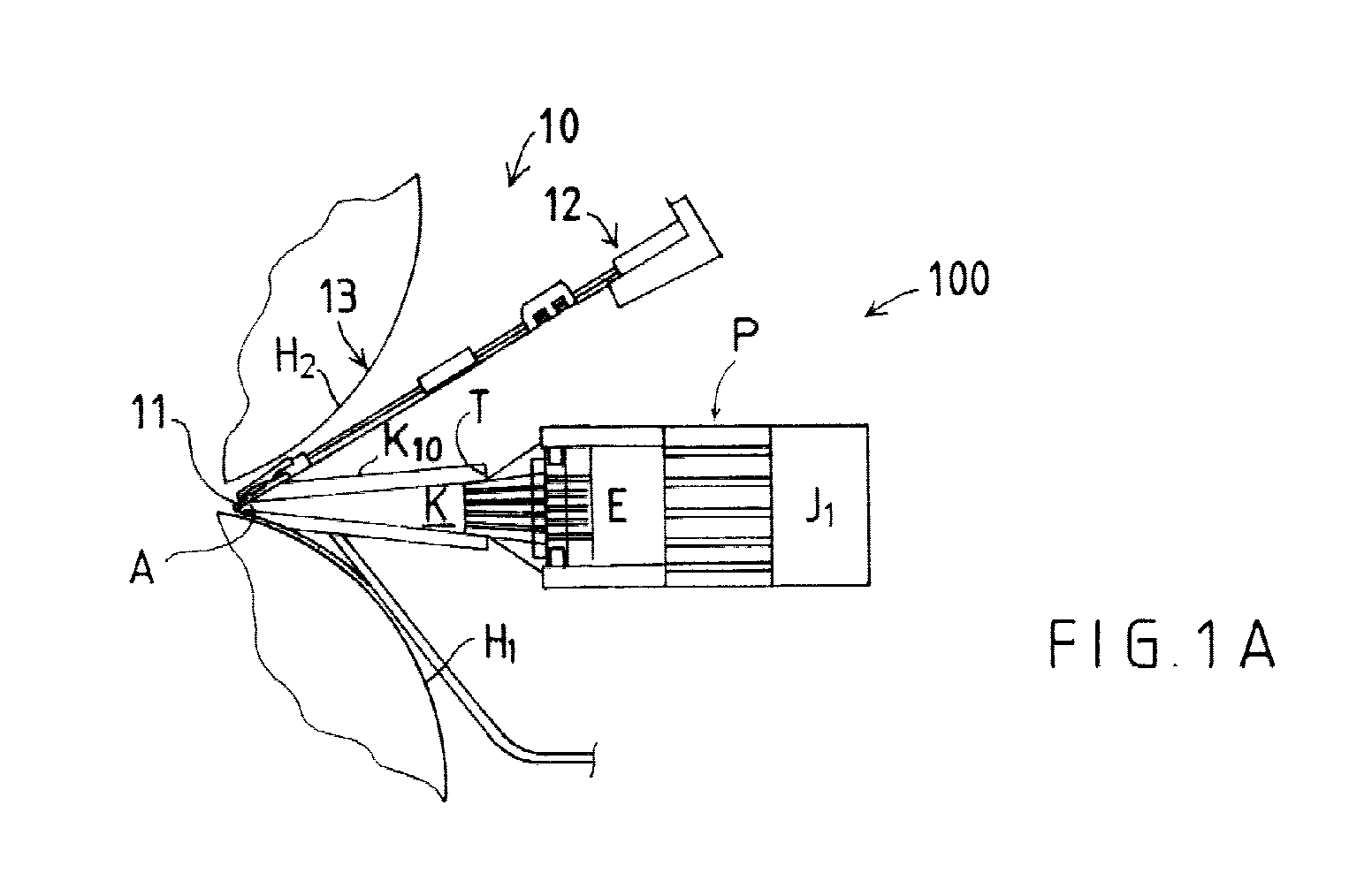
- Figure 1A is a side view of a headbox in a paper machine or board machine or such and of a tip lath control equipment according to the invention located in the headbox.
- Figure 1B illustrates the structure according to Figure 1A and the various functions of the operation are added in the figure for each different actuator group.
- Figure 1C shows in millimetres the magnitude of correction achieved with the different actuators.
- Figure 2 illustrates the formation of the first and second actuators and their connections with the structures.
- Figure 3A shows an embodiment of the invention, wherein the second actuators are mounted into the top front surface of a flexible beam and their spindles are mounted through the said beam and are attached to the tip lath.
- Figure 3B is a sectional view along the line I-I of Figure 3A.
- Figure 4A shows an embodiment of the invention, wherein the first actuators are joined to the top front surface of the flexible beam and also the second actuators are joined to the top front surface of the said flexible beam.
- Figure 4B is a view of the equipment solution in the direction of arrow f 1 of Figure 4A, that is, from above.
- FIG. 1A shows a side view of a headbox 100 in a paper machine or board machine or such and of control equipment 10 for the tip lath 11 according to the invention.
- the headbox 100 shown in the figure includes a set of pipes P after a pulp distributing manifold J 1 , through which pipes the pulp flow is conducted to an intermediate chamber E and further by way of turbulence generator T into lip cone K and from the lip cone through lip slice A into the jaw between formation wires H 1 and H 2 .
- Lip slice A is controlled by bending tip lath 11 with the aid of equipment 12a 1 , 12a 2 ...; 14; 13a 1 , 13a 2 ... located on the top surface of top lip beam K 10 .
- the top lip beam 10 is fixed and includes no tilting joint for top lip beam K 10 .
- tip lath 11 is moved according to the invention by two functionally series-connected actuators 12a 1 , 12a 2 ... and 13a 1 , 13a 2 ...
- the first actuators 12a 1 , 12a 2 ... are located to connect with a bendable and thus movable intermediate part 14, preferably with a beam extending over the width of headbox 100, so that the said actuators 12a 1 , 12a 2 ... are located between the intermediate part 14 and stop face R' of the above frame R.
- the said first actuators 12a 1 , 12a 2 With the aid of the said first actuators 12a 1 , 12a 2 ...
- control of lip slice A is carried out as a rough control, and the said control is preferably used to perform correction of the fibre orientation profile.
- the said first actuators 12a 1 , 12a 2 ... are so-called rough control actuators.
- Zeroing of the headbox lip and exact control of the tip lath are performed by the second actuators 13a 1 , 13a 2 ..., which are so-called fine control equipment functionally located to exert an effect in between the flexible beam 14 and the tip lath 11.
- the first actuators 12a 1 , 12a 2 ... are e.g. hydraulic cylinders or spindles moved by motor-gear combinations.
- the second actuators 13a 1 , 13a 2 ... are preferably fine control spindles 15a 1 , 15a 2 manually controlled only as regards their length.
- first actuators 12a 1 , 12a 2 ... are understood as being equipment which is used to bring about loading and deformation in the intermediate part 14 and further through this in the tip lath 11, whereas the second actuators 13a 1 , 13a 2 ... are understood as being such equipment as fine control spindles manually controlled only as regards their length, which are located with a closer division and which also affect tip lath 11, whereby with the aid of the said second actuators 13a 1 , 13a 2 ... the tip lath 11 can be controlled and bent into its desired shape in the fine control stage.
- Figure 1B illustrates the structure according to Figure 1A and a function is added to its presentation, that is, the function brought about by each group of actuators 12a 1 , 12a 2 ...; 13a 1 , 13a 2 ...
- the first actuators 12a 1 , 12a 2 ... are used to affect the flexible beam 14 and give it a certain bent shape, and the beam's bent shape is transferred further to tip lath 11 through the second actuators 13a 1 , 13a 2 ..., which are e.g. fine control spindles 15a 1 , 15a 2 .
- the fine control proper is performed by the first actuators 12a 1 , 12a 2 ..., which are located between the concerned intermediate part 14, preferably a flexible beam, and tip lath 11.
- the flexible and thus movable intermediate part 14 of the tip lath is a beam extending over the width of the headbox.
- the second actuators 13a 1 , 13a 2 ... are located with a closer division than the first actuators 12a 1 , 12a 2 ...
- the first actuators and second actuators 12a 1 , 12a 2 ...; 13a 1 , 13a 2 ... are functionally in a series in relation to each other.
- Figure 1C also shows in millimetres the magnitude of the correction brought about by the different control equipment when the total control range d is ⁇ 9 mm.
- the size of the correction of tip lath 11 which can be performed by the first actuators 12a 1 , 12a 2 ... is ⁇ 8 mm
- the size of the correction of tip lath 11 which can be performed by the second actuators 13a 1 , 13a 2 ... is ⁇ 1 mm.
- Figure 1C illustrates an embodiment for forming the actuators 12a 1 , 12a 2 ... and 13a 1 , 13a 2 ...
- the first actuators 12a 1 , 12a 2 ... are so-called motor-gear-spindle combinations M 1 , V 1 , 16a 1 , which connect in between the front face R' of frame R and the flexible and thus movable intermediate part 14, preferably a beam.
- Motor M 1 , M 2 ... may be an electric motor.
- fibre orientation control beam 14 is bent by the first actuators 12a 1 , 12a 2 ... and the bent shape given to the beam is passed on through the spindles 15a 1 , 15a 2 ...of the second actuators 13a 1 , 13a 2 ... of tip lath 11 or through similar parts.
- tip lath 11 can be controlled as desired by bending it along its entire length.
- the distance between the first actuators 12a 1 , 12a 2 ... is S 1
- the distance between the second actuators 13a 1 , 13a 2 ... is S 2
- S 1 > S 2 that is, the first actuators 12a 1 , 12a 2 ... are located with a less close division than the second actuators 13a 1 , 13a 2 ...
- the second actuators 13a 1 , 13a 2 ... are located with a closer division than the first actuators 12a 1 , 12a 2 ...
- the top lip beam K 10 is fixed and does not include any tilting joint for the top lip beam K 10 .
- Figure 3A shows an embodiment of the invention, wherein the second actuators 13a 1 , 13a 2 ... are mounted on to the top front face of intermediate part 14, preferably a bendable beam.
- Each actuator 13a 1 , 13a 2 ... can be used to affect a separate fine control spindle 15a 1 , 15a 2 ... and further to affect tip lath 11.
- the fine control spindles 15a 1 , 15a 2 ... are located through beam 14 and further at their one end to connect with tip lath 11.
- the first actuators 12a 1 , 12a 2 ... are also located to connect with the bendable intermediate part 14, preferably a beam, in between stop face R' and intermediate part 14.
- Figure 3B shows a sectional view along line I-I of Figure 3A.
- Figure 4A shows an embodiment of the invention, wherein the stop face R' of the first actuators 12a 1 , 12a 2 ... is located below the first and second actuators 12a 1 , 12a 2 ...; 13a 1 , 13a 2 ...
- the first actuators 12a 1 , 12a 2 affect between the said stop face R' and the flexible intermediate part 14, preferably a beam extending across the width of the headbox, and correspondingly the second actuators 13a 1 , 13a 2 ... affect between the said intermediate part 14 and tip lath 11.
- the second actuators 13a 1 , 13a 2 connect with the top front face of the intermediate part 14, preferably a beam, as do the first actuators 12a 1 , 12a 2 ...
- Figure 4B is a view from above of a structure in the direction of arrow f 1 of Figure 4A.
- the invention concerns control equipment for the headbox tip lath of a paper machine or such and a method of tip lath control.
- the tip lath control equipment (10) includes first actuators (12a 1 , 12a 2 ...), which are located at different points along the headbox (100) width and connect functionally with a bendable intermediate part (14). At the different points along the headbox (100) width there are also second actuators (13a 1 , 13a 2 ...) which are used in the tip lath control. These connect functionally with both the bendable intermediate part (14) and the tip lath (11).
- the first actuators (12a 1 , 12a 2 ...) are used to perform rough control of the tip lath (11) whereas the second actuators (13a 1 , 13a 2 ...) are used to perform fine control of the tip lath (11).
Landscapes
- Paper (AREA)
- Separation, Sorting, Adjustment, Or Bending Of Sheets To Be Conveyed (AREA)
Abstract

Description
Claims (11)
- Control equipment (10) for the headbox (100) tip lath (11) of a paper machine or such, characterised in that the tip lath control equipment (10) includes first actuators (12a1, 12a2 ...), which are located over the width of the headbox (100) and which connect functionally with a bendable intermediate part (14), and that the control equipment includes second actuators (13a1, 13a2 ...), which are used for controlling the tip lath over the headbox (100) width and which connect functionally with the bendable intermediate part (14) and with the tip lath (11), and that with the aid of the first actuators (12a1, 12a2 ...) rough control of the tip lath (11) is carried out and with the aid of the said second actuators (13a1, 13a2 ...) fine control of the tip lath (11) is carried out.
- Tip lath control equipment as defined in claim 1, characterised in that the bendable and thus movable intermediate part (14) is a beam, which extends over the width of the headbox and that the second actuators (13a1, 13a2 ...) are located with a closer division than the first actuators (12a1, 12a2 ...) and that the first and second actuators (12a1, 12a2 ...; 13a1, 13a2 ...) are located functionally in a series in relation to one another.
- Tip lath control equipment as defined in claim 1 or in claim 2, characterised in that the second actuators (13a1, 13a2 ...) are formed by fine control spindles (15a1, 15a2 ...), the length of which can be controlled.
- Tip lath control equipment as defined in any one of the preceding claims, characterised in that the first actuators (12a1, 12a2 ...) are located between a fixed stop face (R') located in a standard position and an intermediate part (14), preferably a bendable beam, and that the second actuators (13a1, 13a2 ...) are located in between the said intermediate part (14) and the tip lath (11) connecting functionally with both the intermediate part (14) and the tip lath (11).
- Tip lath control equipment as defined in any one of the preceding claims, characterised in that the first actuators (12a1, 12a2 ...) are formed by an electric motor (M1, M2 ...), which through a gear is adapted to move a spindle (16a1, 16a2 ...), and that the spindle (16a1, 16a2 ...) at its end is connected with the intermediate part (14) and that the spindle (16a1, 16a2 ...) is also functionally joined through a gearbox (V1, V2 ...) and the motor (M1, M2 ...) to a fixed stop face (R') of the frame (R).
- Tip lath control equipment as defined in any one of the preceding claims, characterised in that the first and second actuators (12a1, 12a2 ...; 13a1, 13a2 ...) used for controlling the tip lath are located on the top surface of the top lip beam (K10) of the lip cone (K) of the headbox (100) in the paper machine or such.
- Tip lath control equipment as defined in claim 1 or in claim 2, characterised in that the second actuators (13a1, 13a2 ...) are connected with the intermediate part (14), preferably a beam, and with its top front face and they further affect the tip lath (11) through the fine control spindles (15a1, 15a2 ...).
- Tip lath control equipment as defined in claim 1, 2 or 7, characterised in that the first actuators (12a1, 12a2 ...) are functionally connected with the intermediate part (14) and with such a stop face (R') which is located in between the intermediate part (14) and the tip lath (11) and below the intermediate part (14).
- Tip lath control equipment as defined in any one of the preceding claims, characterised in that the top lip beam (K10) is fixed and includes no joint for opening the lip cone (K).
- Method for use in controlling the tip lath (11) of the headbox (100) in a paper machine or such, characterised in that first actuators (12a1, 12a2 ...) are used in the tip lath (11) control, which actuators are located in between the bendable intermediate part (14) and a separate stop face (R'), and second actuators (13a1, 13a2 ...), which are located in between the said bendable intermediate part (14) and the tip lath (11), whereby the said first actuators (12a1, 12a2 ...) are used to perform rough control of the tip lath (11), and the said second actuators (13a1, 13a2 ...) are used to perform fine control of the tip lath (11).
- Method as defined in the preceding claims, characterised in that the first and second actuators (12a1, 12a2 ...; 13a1, 13a2 ...) are fitted into the different width positions of the headbox in such a way that the said actuators (12a1, 12a2 ...; 13a1, 13a2 ...) are used to perform control of the tip lath (11) along the tip lath length, and that in the method the said first actuators (12a1, 12a2 ...) are used to affect the intermediate part (14), preferably a bendable beam, extending over the headbox width, in such a way that the bent shape is transferred further from the intermediate part (14) through actuators, e.g. fine control spindles (15a1, 15a2 ...) of the second actuators (13a1, 13a2 ...), to the tip lath (11), and that the fine control proper of the tip lath (11) is performed by the said second actuators (13a1, 13a2 ...), which are preferably fine control spindles (15a1, 15a2 ...).
Applications Claiming Priority (2)
| Application Number | Priority Date | Filing Date | Title |
|---|---|---|---|
| FI20000495 | 2000-03-03 | ||
| FI20000495A FI107170B (en) | 2000-03-03 | 2000-03-03 | Header bar adjustment apparatus and method for adjusting the header bar of a paper machine or similar headbox |
Publications (3)
| Publication Number | Publication Date |
|---|---|
| EP1130157A2 true EP1130157A2 (en) | 2001-09-05 |
| EP1130157A3 EP1130157A3 (en) | 2002-09-18 |
| EP1130157B1 EP1130157B1 (en) | 2006-05-17 |
Family
ID=8557829
Family Applications (1)
| Application Number | Title | Priority Date | Filing Date |
|---|---|---|---|
| EP01105040A Expired - Lifetime EP1130157B1 (en) | 2000-03-03 | 2001-03-01 | Control equipment for the headbox tip lath in a paper machine and method of tip lath control |
Country Status (5)
| Country | Link |
|---|---|
| US (1) | US6402893B2 (en) |
| EP (1) | EP1130157B1 (en) |
| AT (1) | ATE326575T1 (en) |
| DE (1) | DE60119603T2 (en) |
| FI (1) | FI107170B (en) |
Families Citing this family (2)
| Publication number | Priority date | Publication date | Assignee | Title |
|---|---|---|---|---|
| US6984358B2 (en) | 2002-09-13 | 2006-01-10 | Lockheed Martin Corporation | Diffusion bonding process of two-phase metal alloys |
| JP4913510B2 (en) * | 2006-09-05 | 2012-04-11 | 横河電機株式会社 | Simulation method, fiber orientation control method, and fiber orientation control device |
Family Cites Families (11)
| Publication number | Priority date | Publication date | Assignee | Title |
|---|---|---|---|---|
| GB457940A (en) * | 1934-11-19 | 1936-12-09 | Paper Patents Co | Improvements in closed-top spouts for feeding stock to paper making machines |
| US2062471A (en) * | 1935-01-29 | 1936-12-01 | Int Paper Co | Apparatus for the manufacture of paper |
| US2325016A (en) * | 1938-11-16 | 1943-07-20 | Fraser Companies Ltd | Paper machine slice assembly |
| US2264941A (en) * | 1939-03-10 | 1941-12-02 | Paper Patents Co | Slice construction for papermaking machines |
| US2779253A (en) * | 1953-12-24 | 1957-01-29 | Thomas M Owens | Adjustable slice for papermaking machinery |
| DE1187469B (en) * | 1958-01-23 | 1965-02-18 | Rice Barton Corp | Headbox for a paper machine |
| US3334011A (en) * | 1964-12-18 | 1967-08-01 | Allis Chalmers Mfg Co | Headbox with torsion beam support |
| DE3644454C1 (en) * | 1986-12-24 | 1988-08-04 | Voith Gmbh J M | Headbox for a paper machine or the like. |
| US4726883A (en) * | 1987-04-27 | 1988-02-23 | Beloit Corporation | Apparatus for selectively moving the slice lip of a headbox |
| IT1215583B (en) * | 1987-06-25 | 1990-02-14 | Comer Spa | INFLUENCE CASE WITH CHANGE IN THE TURBULENCE OF THE FIBROUS MIXTURE. |
| US5853546A (en) * | 1997-08-21 | 1998-12-29 | Voith Sulzer Paper Technology North America, Inc. | Sealed titanium slice lip for a headbox |
-
2000
- 2000-03-03 FI FI20000495A patent/FI107170B/en not_active IP Right Cessation
-
2001
- 2001-02-23 US US09/791,302 patent/US6402893B2/en not_active Expired - Fee Related
- 2001-03-01 EP EP01105040A patent/EP1130157B1/en not_active Expired - Lifetime
- 2001-03-01 AT AT01105040T patent/ATE326575T1/en active
- 2001-03-01 DE DE60119603T patent/DE60119603T2/en not_active Expired - Lifetime
Also Published As
| Publication number | Publication date |
|---|---|
| FI20000495A0 (en) | 2000-03-03 |
| ATE326575T1 (en) | 2006-06-15 |
| DE60119603T2 (en) | 2007-04-26 |
| FI107170B (en) | 2001-06-15 |
| EP1130157B1 (en) | 2006-05-17 |
| US6402893B2 (en) | 2002-06-11 |
| US20010027851A1 (en) | 2001-10-11 |
| EP1130157A3 (en) | 2002-09-18 |
| DE60119603D1 (en) | 2006-06-22 |
Similar Documents
| Publication | Publication Date | Title |
|---|---|---|
| RU2455156C2 (en) | Device and method for production of gypsum panel | |
| EP1199152A2 (en) | Method and apparatus for adjusting the gap between the rollers in a glue applicator for corrugated board | |
| GB2232456A (en) | Drive wheel phase relationship adjustment device | |
| CH680653A5 (en) | ||
| EP1130157B1 (en) | Control equipment for the headbox tip lath in a paper machine and method of tip lath control | |
| JPH0655113A (en) | Device to measure coating agent on moving substrate | |
| JP2001219218A (en) | Inclined roll type straightening machine | |
| DE3644454C1 (en) | Headbox for a paper machine or the like. | |
| EP1815062B1 (en) | Twin wire gap former paper making machine with a variable wrap impingement shoe | |
| CN201189541Y (en) | Steel bar automatic bending machine | |
| DE102009020532B3 (en) | Production line for cardboard and corrugated base papers | |
| US7004001B2 (en) | Roll forming apparatus for forming sheet material into multiple shapes | |
| US7384511B2 (en) | Device for changing the cloth of a paper machine | |
| DE3836062A1 (en) | FABRIC OUTLET FOR A MACHINE FOR THE PRODUCTION OF FIBERGLASS SHEETS, IN PARTICULAR OF PAPER SHEETS | |
| DE19809480B4 (en) | twin | |
| CN213896377U (en) | Full-automatic online device of raising machine | |
| JPH0644483Y2 (en) | Pinch roll combined use leveler | |
| DE69508136T2 (en) | Device for the zone-by-zone adjustment of the load in the wet end of a paper or cardboard machine | |
| DE4105237C2 (en) | Headbox | |
| NO315570B1 (en) | Apparatus and method for generating turbulence in a blank in a section forming a fourdrinier | |
| US20160130754A1 (en) | Movable foil blade for papermaking on a fourdrinier, including the lead blade on the forming board box | |
| DE4106763A1 (en) | Paper-making stock inlet - monitors gap between the moving channel wall and reference line for correction through heating fluid temp. | |
| JP2712234B2 (en) | Slice deflector indentation pressure control device for double-mesh paper machine. | |
| EP1448321A1 (en) | Inclined position adjustment | |
| JP3486658B2 (en) | Operation method and apparatus capable of changing wire pitch during operation of Fourdrinier with shaking operation |
Legal Events
| Date | Code | Title | Description |
|---|---|---|---|
| PUAI | Public reference made under article 153(3) epc to a published international application that has entered the european phase |
Free format text: ORIGINAL CODE: 0009012 |
|
| AK | Designated contracting states |
Kind code of ref document: A2 Designated state(s): AT BE CH CY DE DK ES FI FR GB GR IE IT LI LU MC NL PT SE TR |
|
| AX | Request for extension of the european patent |
Free format text: AL;LT;LV;MK;RO;SI |
|
| PUAL | Search report despatched |
Free format text: ORIGINAL CODE: 0009013 |
|
| AK | Designated contracting states |
Kind code of ref document: A3 Designated state(s): AT BE CH CY DE DK ES FI FR GB GR IE IT LI LU MC NL PT SE TR |
|
| AX | Request for extension of the european patent |
Free format text: AL;LT;LV;MK;RO;SI |
|
| 17P | Request for examination filed |
Effective date: 20020917 |
|
| AKX | Designation fees paid |
Designated state(s): AT BE CH CY DE DK ES FI FR GB GR IE IT LI LU MC NL PT SE TR |
|
| 17Q | First examination report despatched |
Effective date: 20041104 |
|
| RTI1 | Title (correction) |
Free format text: CONTROL EQUIPMENT FOR THE HEADBOX TIP LATH IN A PAPER MACHINE AND METHOD OF TIP LATH CONTROL |
|
| GRAP | Despatch of communication of intention to grant a patent |
Free format text: ORIGINAL CODE: EPIDOSNIGR1 |
|
| GRAC | Information related to communication of intention to grant a patent modified |
Free format text: ORIGINAL CODE: EPIDOSCIGR1 |
|
| GRAS | Grant fee paid |
Free format text: ORIGINAL CODE: EPIDOSNIGR3 |
|
| GRAA | (expected) grant |
Free format text: ORIGINAL CODE: 0009210 |
|
| AK | Designated contracting states |
Kind code of ref document: B1 Designated state(s): AT BE CH CY DE DK ES FI FR GB GR IE IT LI LU MC NL PT SE TR |
|
| PG25 | Lapsed in a contracting state [announced via postgrant information from national office to epo] |
Ref country code: IT Free format text: LAPSE BECAUSE OF FAILURE TO SUBMIT A TRANSLATION OF THE DESCRIPTION OR TO PAY THE FEE WITHIN THE PRESCRIBED TIME-LIMIT;WARNING: LAPSES OF ITALIAN PATENTS WITH EFFECTIVE DATE BEFORE 2007 MAY HAVE OCCURRED AT ANY TIME BEFORE 2007. THE CORRECT EFFECTIVE DATE MAY BE DIFFERENT FROM THE ONE RECORDED. Effective date: 20060517 Ref country code: BE Free format text: LAPSE BECAUSE OF FAILURE TO SUBMIT A TRANSLATION OF THE DESCRIPTION OR TO PAY THE FEE WITHIN THE PRESCRIBED TIME-LIMIT Effective date: 20060517 Ref country code: FI Free format text: LAPSE BECAUSE OF FAILURE TO SUBMIT A TRANSLATION OF THE DESCRIPTION OR TO PAY THE FEE WITHIN THE PRESCRIBED TIME-LIMIT Effective date: 20060517 Ref country code: CH Free format text: LAPSE BECAUSE OF FAILURE TO SUBMIT A TRANSLATION OF THE DESCRIPTION OR TO PAY THE FEE WITHIN THE PRESCRIBED TIME-LIMIT Effective date: 20060517 Ref country code: LI Free format text: LAPSE BECAUSE OF FAILURE TO SUBMIT A TRANSLATION OF THE DESCRIPTION OR TO PAY THE FEE WITHIN THE PRESCRIBED TIME-LIMIT Effective date: 20060517 Ref country code: NL Free format text: LAPSE BECAUSE OF FAILURE TO SUBMIT A TRANSLATION OF THE DESCRIPTION OR TO PAY THE FEE WITHIN THE PRESCRIBED TIME-LIMIT Effective date: 20060517 |
|
| REG | Reference to a national code |
Ref country code: GB Ref legal event code: FG4D |
|
| REG | Reference to a national code |
Ref country code: CH Ref legal event code: EP |
|
| REG | Reference to a national code |
Ref country code: IE Ref legal event code: FG4D |
|
| REF | Corresponds to: |
Ref document number: 60119603 Country of ref document: DE Date of ref document: 20060622 Kind code of ref document: P |
|
| PG25 | Lapsed in a contracting state [announced via postgrant information from national office to epo] |
Ref country code: SE Free format text: LAPSE BECAUSE OF FAILURE TO SUBMIT A TRANSLATION OF THE DESCRIPTION OR TO PAY THE FEE WITHIN THE PRESCRIBED TIME-LIMIT Effective date: 20060817 Ref country code: DK Free format text: LAPSE BECAUSE OF FAILURE TO SUBMIT A TRANSLATION OF THE DESCRIPTION OR TO PAY THE FEE WITHIN THE PRESCRIBED TIME-LIMIT Effective date: 20060817 |
|
| PG25 | Lapsed in a contracting state [announced via postgrant information from national office to epo] |
Ref country code: ES Free format text: LAPSE BECAUSE OF FAILURE TO SUBMIT A TRANSLATION OF THE DESCRIPTION OR TO PAY THE FEE WITHIN THE PRESCRIBED TIME-LIMIT Effective date: 20060828 |
|
| PG25 | Lapsed in a contracting state [announced via postgrant information from national office to epo] |
Ref country code: PT Free format text: LAPSE BECAUSE OF FAILURE TO SUBMIT A TRANSLATION OF THE DESCRIPTION OR TO PAY THE FEE WITHIN THE PRESCRIBED TIME-LIMIT Effective date: 20061017 |
|
| NLV1 | Nl: lapsed or annulled due to failure to fulfill the requirements of art. 29p and 29m of the patents act | ||
| REG | Reference to a national code |
Ref country code: CH Ref legal event code: PL |
|
| PLBE | No opposition filed within time limit |
Free format text: ORIGINAL CODE: 0009261 |
|
| STAA | Information on the status of an ep patent application or granted ep patent |
Free format text: STATUS: NO OPPOSITION FILED WITHIN TIME LIMIT |
|
| 26N | No opposition filed |
Effective date: 20070220 |
|
| EN | Fr: translation not filed | ||
| PG25 | Lapsed in a contracting state [announced via postgrant information from national office to epo] |
Ref country code: IE Free format text: LAPSE BECAUSE OF NON-PAYMENT OF DUE FEES Effective date: 20070301 Ref country code: MC Free format text: LAPSE BECAUSE OF NON-PAYMENT OF DUE FEES Effective date: 20070331 |
|
| PG25 | Lapsed in a contracting state [announced via postgrant information from national office to epo] |
Ref country code: FR Free format text: LAPSE BECAUSE OF FAILURE TO SUBMIT A TRANSLATION OF THE DESCRIPTION OR TO PAY THE FEE WITHIN THE PRESCRIBED TIME-LIMIT Effective date: 20070309 Ref country code: GR Free format text: LAPSE BECAUSE OF FAILURE TO SUBMIT A TRANSLATION OF THE DESCRIPTION OR TO PAY THE FEE WITHIN THE PRESCRIBED TIME-LIMIT Effective date: 20060818 |
|
| PG25 | Lapsed in a contracting state [announced via postgrant information from national office to epo] |
Ref country code: FR Free format text: LAPSE BECAUSE OF FAILURE TO SUBMIT A TRANSLATION OF THE DESCRIPTION OR TO PAY THE FEE WITHIN THE PRESCRIBED TIME-LIMIT Effective date: 20060517 |
|
| PGFP | Annual fee paid to national office [announced via postgrant information from national office to epo] |
Ref country code: GB Payment date: 20090325 Year of fee payment: 9 |
|
| PG25 | Lapsed in a contracting state [announced via postgrant information from national office to epo] |
Ref country code: CY Free format text: LAPSE BECAUSE OF FAILURE TO SUBMIT A TRANSLATION OF THE DESCRIPTION OR TO PAY THE FEE WITHIN THE PRESCRIBED TIME-LIMIT Effective date: 20060517 Ref country code: LU Free format text: LAPSE BECAUSE OF NON-PAYMENT OF DUE FEES Effective date: 20070301 |
|
| PG25 | Lapsed in a contracting state [announced via postgrant information from national office to epo] |
Ref country code: TR Free format text: LAPSE BECAUSE OF FAILURE TO SUBMIT A TRANSLATION OF THE DESCRIPTION OR TO PAY THE FEE WITHIN THE PRESCRIBED TIME-LIMIT Effective date: 20060517 |
|
| GBPC | Gb: european patent ceased through non-payment of renewal fee |
Effective date: 20100301 |
|
| PG25 | Lapsed in a contracting state [announced via postgrant information from national office to epo] |
Ref country code: GB Free format text: LAPSE BECAUSE OF NON-PAYMENT OF DUE FEES Effective date: 20100301 |
|
| PGFP | Annual fee paid to national office [announced via postgrant information from national office to epo] |
Ref country code: DE Payment date: 20120323 Year of fee payment: 12 |
|
| PGFP | Annual fee paid to national office [announced via postgrant information from national office to epo] |
Ref country code: IT Payment date: 20120328 Year of fee payment: 12 |
|
| PGFP | Annual fee paid to national office [announced via postgrant information from national office to epo] |
Ref country code: AT Payment date: 20120313 Year of fee payment: 12 |
|
| REG | Reference to a national code |
Ref country code: AT Ref legal event code: MM01 Ref document number: 326575 Country of ref document: AT Kind code of ref document: T Effective date: 20130301 |
|
| REG | Reference to a national code |
Ref country code: DE Ref legal event code: R119 Ref document number: 60119603 Country of ref document: DE Effective date: 20131001 |
|
| PG25 | Lapsed in a contracting state [announced via postgrant information from national office to epo] |
Ref country code: DE Free format text: LAPSE BECAUSE OF NON-PAYMENT OF DUE FEES Effective date: 20131001 Ref country code: AT Free format text: LAPSE BECAUSE OF NON-PAYMENT OF DUE FEES Effective date: 20130301 |
|
| PG25 | Lapsed in a contracting state [announced via postgrant information from national office to epo] |
Ref country code: IT Free format text: LAPSE BECAUSE OF NON-PAYMENT OF DUE FEES Effective date: 20130301 |