EP1129934A2 - Motor-driven bicycle - Google Patents
Motor-driven bicycle Download PDFInfo
- Publication number
- EP1129934A2 EP1129934A2 EP01103473A EP01103473A EP1129934A2 EP 1129934 A2 EP1129934 A2 EP 1129934A2 EP 01103473 A EP01103473 A EP 01103473A EP 01103473 A EP01103473 A EP 01103473A EP 1129934 A2 EP1129934 A2 EP 1129934A2
- Authority
- EP
- European Patent Office
- Prior art keywords
- self
- running
- motor
- acceleration
- drive motor
- Prior art date
- Legal status (The legal status is an assumption and is not a legal conclusion. Google has not performed a legal analysis and makes no representation as to the accuracy of the status listed.)
- Granted
Links
Images


Classifications
-
- B—PERFORMING OPERATIONS; TRANSPORTING
- B62—LAND VEHICLES FOR TRAVELLING OTHERWISE THAN ON RAILS
- B62M—RIDER PROPULSION OF WHEELED VEHICLES OR SLEDGES; POWERED PROPULSION OF SLEDGES OR SINGLE-TRACK CYCLES; TRANSMISSIONS SPECIALLY ADAPTED FOR SUCH VEHICLES
- B62M6/00—Rider propulsion of wheeled vehicles with additional source of power, e.g. combustion engine or electric motor
- B62M6/40—Rider propelled cycles with auxiliary electric motor
- B62M6/45—Control or actuating devices therefor
-
- B—PERFORMING OPERATIONS; TRANSPORTING
- B62—LAND VEHICLES FOR TRAVELLING OTHERWISE THAN ON RAILS
- B62M—RIDER PROPULSION OF WHEELED VEHICLES OR SLEDGES; POWERED PROPULSION OF SLEDGES OR SINGLE-TRACK CYCLES; TRANSMISSIONS SPECIALLY ADAPTED FOR SUCH VEHICLES
- B62M6/00—Rider propulsion of wheeled vehicles with additional source of power, e.g. combustion engine or electric motor
- B62M6/40—Rider propelled cycles with auxiliary electric motor
- B62M6/55—Rider propelled cycles with auxiliary electric motor power-driven at crank shafts parts
Landscapes
- Engineering & Computer Science (AREA)
- Chemical & Material Sciences (AREA)
- Combustion & Propulsion (AREA)
- Transportation (AREA)
- Mechanical Engineering (AREA)
- Electric Propulsion And Braking For Vehicles (AREA)
- Memory System Of A Hierarchy Structure (AREA)
- Vehicle Body Suspensions (AREA)
- Control Of Transmission Device (AREA)
Abstract
[Solving Means] A motor-driven bicycle, which includes a drive motor for generating a self-running power in response to an operated amount of a self-running operation by a driver, is provided with an acceleration detecting portion 203 for detecting an acceleration, and a rapid acceleration suppressing control portion 205 for controlling the self-running power on the basis of the detected acceleration. If the detected acceleration is more than a specific reference acceleration, the rapid acceleration suppressing control portion 205 gradually reduces the self-running power to be supplied to a drive motor M from a reference value determined in response to the amount of the self-running operation, and thereafter, if the acceleration is less than the reference acceleration, the control portion 205 gradually increases the self-running power to be supplied to the drive motor M up to the reference value determined in response to the amount of the self-running operation.
Description
- The present invention relates to a motor-driven bicycle including a drive motor for generating a self-running power in response to a self-running operation by a driver, and particularly to a motor-driven bicycle capable of obtaining an optimum acceleration irrespective of a road condition, a variation in load such as a deadweight, and the like. The present invention also relates to a motor-driven bicycle capable of outputting a self-running power corresponding to a walking speed when the bicycle is pushed by the hands of a walking driver.
- Unlike a motor-assisted bicycle, called an assist bicycle, including an electric motor for generating an assisting power in response to a leg-power inputted to a crank shaft, wherein a synthetic power of the leg-power and assisting power is transmitted to a drive wheel, a motor-driven bicycle including a drive motor for generating a self-running power in response to an operation by a driver has been proposed, for example, in Japanese Patent Laid-open No. Hei 9-263289. The motor-driven bicycle is allowed to obtain a self-running power in response to an operated amount only by a simple operation irrespective of a leg-power generated by the driver.
- Since the above motor-driven bicycle is heavier than a conventional bicycle, it is desirable to generate a weak self-running output corresponding to a walking speed when a vehicle is pushed by the hands of a walking driver. For this reason, according to the above motor-driven bicycle, a second throttle lever for self-running at a walking speed is provided separately from a normal throttle lever, wherein a self-running output corresponding to a walking speed is generated by operating the second throttle lever.
- Further, according to the above motor-driven bicycle, to decide whether or not the vehicle is pushed by the driver, a sensor or a switch for detecting whether or not a driver is sitting on a seat is provided on a seating surface of the seat, wherein a self-running output corresponding to a walking speed is generated only when the throttle lever is operated.
- In the above motor-driven bicycle, since the self-running power is determined in response to only an amount of a self-running operation by a driver, if the self-running power is determined in response to the operated amount, for example, in a running state on a flat road, the output becomes insufficient in a running state on an ascending slope and becomes excessive in a running state on a descending slope, whereby it fails to obtain a desirable drivability. In addition to the road condition, if the total weight including a driver's weight and a baggage's deadweight is larger than a reference value, the output becomes insufficient, and if the total weight is smaller than the reference value, the output becomes excessive.
- Further, for a conventional assist bicycle, the output of a drive motor is dependent on a value of leg-power, and accordingly, an overload is not applied to the drive motor for a long time because a drive motor cannot continue to input a large leg-power for a long time. On the contrary, for a motor-driven bicycle, since a self-running power is generated in response to an operated amount of a self-running operation by a driver, an overload may be applied to the drive motor for along time.
- A first object of the present invention is to solve the above-described problem of the related art, and to provide a motor-driven bicycle capable of obtaining an optimum acceleration irrespective of a road condition or a vibration in load such as a deadweight.
- A second object of the present invention is to solve the above-described problem of the related art, and to provide a motor-driven bicycle capable of suitably limiting the output of a drive motor, thereby preventing the drive motor from being continuously, severely operated.
- In the related art motor-driven bicycle, to output a self-running power corresponding to a walking speed, a second throttle lever for self-running at a walking speed must be provided separately from a throttle lever, and a seating sensor and its signal line must be additionally provided. As a result, there occurs a technical problem that the vehicle weight is increased along with an increase in the number of parts; the production steps are complicated; and the production cost is raised.
- A third object of the present invention is to solve the above-described problem of the related art, and to provide a motor-driven bicycle capable of realizing a self-running function at a walking speed with a simple configuration.
- To achieve the above objects, the present invention provides the following means:
- (1) A motor-driven bicycle including a drive motor for generating a self-running power in response to an operated amount of a self-running operation by a driver, characterized in that the motor-driven bicycle further includes acceleration detecting means for detecting an acceleration, and control means for controlling the self-running power on the basis of the acceleration detected by the acceleration detecting means.
- (2) A motor-driven bicycle including a drive motor for generating a self-running power in response to an operated amount of a self-running operation by a driver, characterized in that the motor-driven bicycle further includes output limiting means for limiting the self-running power to a specific value. According to the first feature (1), since the self-running power is controlled on the basis of a correlation between the operated amount of a self-running operation and an acceleration, it is possible to obtain an acceleration in response to the operated amount of a self-running operation irrespective of a road condition, a deadweight, and the like.According to the second feature (2), since the self-running power generated from the drive motor in response to the operated amount of a self-running operation can be limited, it is possible to prevent the drive motor from being severely operated.
- (3) A motor-driven bicycle including self-running operation inputting means for inputting a self-running operation by a driver, and a drive motor for generating a self-running power in response to an amount of said self-running operation, characterized in that said bicycle further includes hand-pushing drive control means for making said drive motor generate a self-running power corresponding to a walking speed in response to the self-running operation inputted from said self-running operation inputting means.
-
- According to the third feature (3), since a self-running power corresponding to a walking speed can be generated by using the self-running operation inputting means for generating a general self-running power, the motor-driven bicycle having a self-running function at a walking speed can be realized with a simple configuration without provision of a plurality of self-running operation inputting means.
- The present invention exhibits the following effects:
- (1) Since a self-running power is controlled on the basis of a correlation between the operated amount of a self-running operation and an acceleration, it is possible to obtain an acceleration in response to the operated amount of a self-running operation irrespective of a road condition, a deadweight, and the like.
- (2) If an acceleration is more than a specific reference acceleration, a self-running power to be supplied to the drive motor is gradually reduced from a reference value determined in response to the operated amount of a self-running operation. Accordingly, the self-running power is reduced under an easy acceleration environment, for example, in a running state on a descending slope or with a small deadweight, to obtain a suitable feeling of acceleration. After that, if the detected acceleration is less than the reference acceleration, the self-running power to be supplied to the drive motor is gradually increased to the reference value determined in response to the operated amount of a self-running operation, and accordingly, it is possible to obtain a desirable feeling of acceleration even after the easy acceleration environment is eliminated.
- (3) Since the output limiting means for limiting a self-running power of the drive motor to a specific value is provided so as to limit a self-running power generated by the drive motor in response to the operated amount of a self-running operation, it is possible to prevent the drive motor from being severely operated.
- (4) Since a self-running power of the drive motor is limited to a value being equal to or less than two times the rating of the drive motor, it is possible to obtain a sufficient self-running power without severe operation of the drive motor.
- (5) Since a self-running power corresponding to a walking speed can be generated by using the self-running operation inputting means for generating a general self-running power, the motor-driven bicycle having a self-running function at a walking speed can be realized with a simple configuration without provision of a plurality of self-running operation inputting means.
- (6) Since it is decided whether or not a self-running operation is performed in the driver's non-riding state, and a self-running power matched to a walking speed is generated only when it is decided that the self-running operation is performed in the driver's non-riding state, it is possible to eliminate an inconvenience that a self-running power matched to a walking speed is outputted in the driver's riding state.
- (7) Since it is decided, on the basis of an acceleration of the vehicle, a rate of change in rotational speed of the drive motor, or a rate of change of a drive current of the drive motor, that the self-running operation is performed in the driver's non-riding state, it is possible to eliminate the need of additionally providing a sensor or a switch for detecting the driver's non-riding state.
-
- Hereinafter, the present invention will be described in detail with reference to the accompanying drawings.
- Fig. 1 is a view showing a configuration of a motor-driven bicycle to which the present invention is applied.
- Fig. 2 is a block diagram of a controller shown in FIG. 1.
- Fig. 3 is a flow chart showing an operation of the controller.
- Fig. 4 is a flow chart showing a rapid acceleration suppressing control.
- Fig. 5 is a flow chart showing a gear-shift control.
- Fig. 6 is a flow chart showing a motor output limiting control.
- Fig. 7 is a view showing a gear-shift control method upon shift-up from the "second speed" to the "third speed".
- Fig. 8 is a view showing a gear-shift control method upon shift-down from the "second speed" to the "first speed".
- Fig. 9 is a view showing a gear-shift control method upon shift-up from the "first speed" to the "second speed".
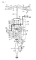
- FIG. 1 is a view showing a configuration of a motor-driven bicycle to which the present invention is applied. In this figure, parts not necessary for description of the present invention are omitted.
- Like a conventional bicycle, a
handlebar 10 includes at its left end portion abrake lever 11 for a rear wheel and at its right end portion abrake lever 13 for a front wheel. Thehandlebar 10 also includes in the vicinities of fulcrums of the brake levers 11 and 13brake switches handlebar 10 further includes at its right end portion athrottle lever 16 as self-running input means for indicating generation of a self-running power to a drive motor M (which will described later), and athrottle opening sensor 15 for detecting an operated angle th as an operated amount. - A body frame has at its central portion a
power unit 2 for selectively carrying out "self-running" by the drive motor M and "assist-running" for assisting a leg power by a drive force of the drive motor M. A leg-power inputted to acrank shaft 30 from left andright crank pedals way clutch 26 to a large-diameter gear 36 coaxially connected to thecrank shaft 30, and is further transmitted via afirst idle shaft 35 to an output shaft 34. - A drive force generated by the drive motor M is transmitted via a
second idle shaft 36 to anidle gear 37. Theidle gear 37 is connected via a one-way clutch 29 to thefirst idle shaft 35. The drive force having been transmitted to theidle gear 37 is transmitted via thefirst idle shaft 35 to the output shaft 34. One end of the output shaft 34 is exposed to the outside of thepower unit 2, and adrive sprocket 32 is connected to the exposed end of the output shaft 34. - A
motor rotation sensor 25 detects a rotational speed NM of the drive motor M.A temperature sensor 24 detects a temperature TM of the drive motor M. A leg-power sensor 23 detects a leg-power inputted to thecrank shaft 30. Acrank rotation sensor 22 detects a rotational speed NC of thecrank shaft 30. Acurrent sensor 27 detects a drive current IM of the drive motor M. Output signals of the above-described sensors are inputted to acontroller 20. - A driven sprocket 33 and a four-
step gear shifter 19 are provided on an axle of arear wheel 31 as a drive wheel. Thedrive sprocket 32 of the output shaft 34 is connected to the driven sprocket 33 via achain 39. An automatic gear-shift actuator 17 outputs a gear-shift step signal DG representative of a gear-shift step in response to a gear-shift command SG outputted from thecontroller 20. Thegear shifter 19 is driven on the basis of the gear-shift step signal DG. A rotational speed V of therear wheel 31 is detected by avehicle speed sensor 18, and a signal of thevehicle speed sensor 18 is inputted to thecontroller 20. - FIG. 2 is a block diagram showing a configuration of a main portion of the
controller 20. In this figure, the same characters as those shown in FIG. 1 designate the same or similar parts. - In a self-running reference
duty ratio map 201, a reference duty ratio Drefl of a drive current IM to be supplied to the drive motor M upon self-running is previously registered as a function of the throttle opening angle th detected by thethrottle opening sensor 15, the vehicle speed V, and a gear step G. In an assist-running referenceduty ratio map 202, a reference duty ratio Dref2 of the drive current IM to be supplied to the drive motor M upon assist-running is previously registered as a function of the leg-power F detected by the leg-power sensor 23 and the vehicle speed V detected by thevehicle speed sensor 18. - It should be noted that in place of detection of the vehicle speed V by the
vehicle speed sensor 18, the vehicle speed V may be detected, by a vehiclespeed detecting portion 213 additionally provided, on the basis of the gear-shift step signal DG, which is representative of the gear-shift step G and which is outputted from the automatic gear-shift actuator 17, and the motor rotational speed NM. - An
acceleration detecting portion 203 detects an acceleration ΔV on the basis of a rate of change in vehicle speed V with elapsed time. A gearstep deciding portion 204 decides the present gear step G on the basis of the detected vehicle speed V and motor rotational speed NM. A rapid acceleration suppressingcontrol portion 205 compares the detected acceleration ΔV with a reference acceleration ΔVref, and instructs, if the detected acceleration Δv is more than the reference acceleration ΔVref, a duty ratio correcting portion 208 (which will be described later) to correct a duty ratio so as to suppress rapid acceleration. - Referring to a gear shifting vehicle speed (Vch) data table 206a, a gear-
shift control portion 206 decides, on the basis of the detected acceleration ΔV and vehicle speed V and the present gear step G decided by the gearstep deciding portion 204, whether or not the present running state is a gear-shift timing state. The decided result is supplied to the dutyratio correcting portion 208 and is also outputted to the gear-shift actuator 17. - A non-riding self-running deciding
portion 207 decides, on the basis of the present gear step G and motor rotational speed NM, whether or not the present self-running operation is performed in the driver's non-riding state. If it is decided that the self-running operation is performed in the driver's non-riding state, a hand-pushingdrive control portion 211 instructs the dutyratio correcting portion 208 to correct a duty ratio so as to generate a self-running power corresponding to a walking speed. - A during-
braking control portion 210 instructs the dutyratio correcting portion 208 to correct a duty ratio so as to control a self-running power on the basis of the presence or absence of a braking operation and the vehicle speed V. To be more specific, if the on-states of the brake switches 12 and 14 are detected during running of the vehicle, the during-braking control portion 210 instructs the dutyratio correcting portion 208 to correct a duty ratio so as to allow the drive motor M to generate a drive force being small enough to bring about a state in which no load is apparently applied to the drive motor M. Meanwhile, if a self-running operation is performed in a vehicle stoppage state in which the brake switches 12 and 14 are in the on-states, the during-braking control portion 210 instructs the dutyratio correcting portion 208 to correct a duty ratio so as to allow the drive motor M to generate a drive force corresponding to an operated amount of the self-running operation. - A motor
output limiting portion 209 monitors an operational state of the drive motor M on the basis of the drive current IM of the drive motor M detected by thecurrent sensor 27 and the temperature TM of the drive motor M detected by thetemperature sensor 24, and instructs, if the drive motor M is in a severe operational state, the dutyratio correcting portion 208 to correct a duty ratio so as to limit the self-running power. - The duty
ratio correcting portion 208 corrects, as will be described in detail later, the reference duty ratio Dref1 or Dref2 obtained from theduty ratio map control portion 205, the gear-shift control portion 206, the hand-pushingcontrol portion 211, the during-braking control portion 210, and the motoroutput limiting portion 209, and outputs the corrected result as a target duty ratio DM. - A method of controlling the drive motor M upon self-running by the
controller 20 will be described with reference to a flow chart shown in FIG. 3. - In step S11, an opening angle th of the
throttle lever 16 is detected by thethrottle opening sensor 15; a vehicle speed V is detected by avehicle speed sensor 18; and a rotational speed NM of the drive motor M is detected by themotor rotation sensor 25. In step S12, an acceleration ΔV is calculated on the basis of the vehicle speed V detected in step S11 by theacceleration detecting portion 203. In step S13, the present gear step G is decided on the basis of a correlation between the vehicle speed V and the motor rotational speed NM by the gearstep deciding portion 204. It should be noted that the present gear step G may be decided on the basis of the gear-shift step signal DG outputted from the automatic gear-shift actuator 17. - In step S14, a drive current IM of the drive motor M is detected by the
current sensor 27, and a temperature TM of the drive motor M is detected by thetemperature sensor 24. In step S15, a reference duty ratio Drefl upon self-running is retrieved from theduty ratio map 201 for self-running on the basis of the throttle opening angle th and vehicle speed V detected in step S11 and the present gear step G decided in step S13. - In step S16, on the basis of the states of the brake switches 12 and 14, it is decided by the during-
braking control portion 210 whether or not a braking operation has been performed. If it is decided that the braking operation has not been performed, the process goes on to step S17. In step S17, on the basis of an increase ratio ΔNM of the motor rotational speed NM, it is decided by the non-riding self-running decidingportion 207 whether or not the driver has operated thethrottle lever 16 in the driver's non-riding state. If the increase ratio ΔNM of the motor rotational speed NM is a reference increase ratio ΔNref or more, it is decided that the driver has operated thethrottle lever 16 in the driver's non-riding state, and the process goes on to step S24. If the increase ratio ΔNM is less than the reference increase ratio ΔNref, it is decided that the driver has operated thethrottle lever 16 in the driver's riding state, and the process goes on to step S18. - The parameter for deciding whether or not the driver has operated the
throttle lever 16 in the driver's non-riding state is not limited to the above-described increase ratio ΔNM of the motor rotational speed NM. For example, the acceleration ΔV may be used as the decision parameter. In this case, if the acceleration ΔV is larger than a reference acceleration, it may be decided that the driver has operated thethrottle lever 16 in the driver's non-riding state. Alternatively, a change ratio of the drive current of the drive motor M may be used as the decision parameter. In this case, if the change ratio of current is larger than a reference change ratio of current, it may be decided that the driver has operated thethrottle lever 16 in the driver's non-riding state. - In this way, according to this embodiment, it is decided, on the basis of the increase ratio of the motor rotational speed, acceleration of the vehicle, or the change ratio of a drive current of the drive motor, whether or not the self-running operation is performed in the driver's non-riding state, and accordingly, it is possible to eliminate the need of providing a sensor or a switch for detecting the driver's non-riding state.
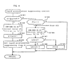
- In step S18, a routine of "rapid acceleration suppressing control" for ensuring a sufficient acceleration performance while suppressing rapid acceleration is executed.
- FIG. 4 is a flow chart indicating a control content of the "rapid acceleration suppressing control". The control content is determined such that an acceleration corresponding to an operated amount of the
throttle lever 16 can be obtained irrespective of a road surface state, a deadweight, and the like by controlling a self-running power of the drive motor M on the basis of a correlation between an operated amount of thethrottle lever 16 and an acceleration. - In step S181, the present acceleration ΔV is compared with a reference acceleration ΔVref by the rapid acceleration suppressing
control portion 205. If the acceleration ΔV is more than the reference acceleration ΔVref, it is decided that the vehicle is in the rapid acceleration state, and the process goes on to step S182. In step S182, the reference duty ratio Dref1 retrieved from theduty ratio map 201 upon self-running is multiplied by a correction coefficient smaller than "1" by the dutyratio correcting portion 208, and the calculated result is taken as a target duty ratio DM. - In this embodiment, the correction coefficient is defined as "0.9k1", and the initial value of the exponent kl is set to "1". Accordingly, in the initial state, a value being 0.9 times the reference duty ratio Dref1 decided by the
map 201 is registered as the target duty ratio DM. In step S183, the value of the exponent k1 is incremented by "1". In step S184, a rapid acceleration suppressing flag F1 is set to "1". - After that, since the above steps are repeated to increase the value of the exponent k1 until it is decided in step S181 that the acceleration ΔV is less than the reference acceleration ΔVref, the target duty ratio DM is gradually reduced depending on the value of the exponent k1.
- If it is decided in step S181, as a result of gradually reducing the target duty ratio DM, that the acceleration ΔV is less than the reference acceleration ΔVref, the process goes on to step S185 in which it is decided that the rapid acceleration suppressing flag F1 is "1". If it is decided that the flag F1 is set to "1", the process goes on to step S186 in which the duty ratio having been gradually reduced in step S182 is gradually increased.
- In step S186, the present target duty ratio DM is multiplied by a correction coefficient smaller than "1", and the calculated result is taken as a new target duty ratio DM. In this embodiment, the correction coefficient is defined as a value of "0.9k2", and the initial value of the exponent k2 is set to "5". In the initial state, a value being 0.59 (= 0.95) times the target duty ratio DM is taken as a target duty ratio DM.
- In step S187, it is decided whether or not the exponent k2 is reduced to "0". Since the exponent k2 is "5" in the initial state, the process goes on to step S188. In step S188, the value of the exponent k2 is decremented by "1". If it is decided in step S187 that the exponent k2 is "0", the process goes on to step S189 in which the rapid acceleration suppressing flag F1 is reset, thereby ending the routine of "rapid acceleration suppressing control" shown in FIG. 4.
- In this way, according to this embodiment, if the acceleration ΔV is more than the reference acceleration ΔVref, the correction coefficient is, in step S182, gradually reduced for gradually reducing the target duty ratio DM, and thereafter, if the acceleration ΔV is less than the reference acceleration ΔVref, the correction coefficient is, in step S186, gradually increased for gradually increasing the target duty ratio DM, thereby compensating for the above-described gradually reduced amount of the target duty ratio DM. Accordingly, it is possible to obtain a sufficient acceleration performance while suppressing rapid acceleration.
- Referring again to FIG. 3, in step S19, it is decided by the gear-
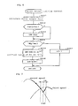
shift control portion 206 whether or not automatic gear-shift should be performed. If an absolute value of a difference between the present vehicle speed V and a gear-shift vehicle speed Vch stored in the gear-shift vehicle speed data table 206a for each gear step is less than a reference speed VA, the process goes on to step S20 in which a "gear-shift control" is executed for automatic gear-shift. As the gear-shift vehicle speed Vch, a gear-shift vehicle speed Vch12 indicating a gear-shift timing between "first speed"/ "second speed", a gear-shift vehicle speed Vch23 indicating a gear-shift timing between "second speed"/ "third speed", and a gear-shift vehicle speed Vch34 indicating a gear-shift timing between "third speed"/"fourth speed" are registered. Either of the gear-shift vehicle speeds Vch12, Vch23, and Vch34 is selected on the basis of the present gear step G. - FIG. 5 is a flow chart indicating the routine of the "gear-shift control", which mainly shows the operation of the gear-
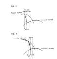
shift control portion 206. - In step S201, it is decided whether or not a variation in torque caused by gear-shift is increased or decreased. For example, upon shift-up from the "second speed" to the "third speed", as shown in FIG. 7, a torque at the "third speed" is larger than that of the "second speed" at the gear-shift vehicle speed Vch23, and accordingly, it is decided in step S201 that the torque is increased after gear-shift, and the process goes on to step S202. Similarly, upon shift-down from the "second speed" to the "first speed", as shown in FIG. 8, a torque at the "first speed" is larger than that of the "second speed" at the gear-shift vehicle speed Vch12, and accordingly, it is decided in step S201 that the torque is increased after gear-shift, and the process goes on to step S202.
- In step S202, referring to the gear-shift vehicle speed data table 206a, the gear-
shift control portion 206 decides whether or not the present vehicle speed V reaches a predetermined gear-shift vehicle speed Vch corresponding to the present gear step. Here, if it is decided that, as shown in FIG. 7, the vehicle speed V reaches the gear-shift vehicle speed Vch23 during running at the "second speed" and thereby the timing of shift-up to the "third speed" comes, the process goes on to step S203 in which the gear-shift actuator 17 is driven for gear-shift (shift-up). In step S204, the present target duty ratio DM is multiplied by a correction coefficient smaller than "1", and the calculated result is taken as a new target duty ratio DM. - According to this embodiment, the correction coefficient is defined as "0.9k3", and the initial value of the exponent k3 is set to "5". Accordingly, in the initial state, a value being 0.59 times (= 0.95) the present target duty ratio DM is taken as a target duty ratio DM. As a result, as shown in FIG. 7, a torque immediately after shift-up to the "third speed" is lowered to the same level as that of a torque at the "second speed", with a result that it is possible to prevent occurrence of a gear-shift shock due to the gear-shift.
- In step S205, it is decided whether or not the exponent k3 is "0". Since the exponent k3 is "5" in the initial state, the process goes on to step S207 in which the exponent k3 is decremented by "1".
- After that, the above-described steps are repeated, to gradually reduce the value of exponent k3, thereby gradually reducing the target duty ratio DM. Accordingly, as shown in FIG. 7, a self-running power of the drive motor M is rapidly reduced at the gear-shift vehicle speed Vch23, and then gradually increased to be returned to the original target duty ratio DM, thereby obtaining a proper torque corresponding to the gear step.
- Similarly, as shown in FIG. 8, even in the case where the vehicle speed V is lowered to the gear-shift vehicle speed Vch12 during running at the "second speed" to be thus shifted down to the "first speed", the target duty ratio DM is reduced such that a torque immediately after shift-down to the "first speed" is reduced to the same level as that of a torque at the "second speed", and then the target duty ratio DM is gradually increased to be returned to the original target duty ratio DM, thereby obtaining a desirable shift feeling.
- On the other hand, upon shift-up from the "first speed" to the "second speed", as shown in FIG. 9, since a torque at the "second speed" is smaller than a torque at the "first speed" at the gear-shift vehicle speed Vch12, it is decided in step S201 that the torque is reduced after gear-shift, and the process goes on to step S208 in which it is decided whether or not the present vehicle speed V reaches a predetermined gear-shift vehicle speed Vch12. If it is decided that the vehicle speed does not reach the gear-shift vehicle speed Vch12, the process goes on to step S209 in which the present target duty ratio DM is multiplied by a correction coefficient smaller than "1" and the calculated result is taken as a new target duty ratio DM.
- In this embodiment, the correction coefficient is defined as "0.9k4", and the initial value of the exponent k4 is set to "1". Accordingly, in the initial state, a value being 0.9 times the present target duty ratio DM is taken as a target duty ratio. In step S210, the exponent k4 is incremented by "1".
- After that, the above-described steps are repeated until it is decided in step S208 that the vehicle speed V reaches the gear-shift vehicle speed Vch12, whereby the target duty ratio DM is gradually reduced according to the value of the exponent k4. Accordingly, as shown in FIG. 9, the torque is gradually reduced.
- If it is decided in step S208 that the vehicle speed V reaches the gear-shift vehicle speed Vch12, the process goes on to step S211 in which the gear-shift actuator is driven for gear-shift. At this time, according to this embodiment, since a torque at the "first speed" is reduced to the same level as that of a torque at the "second speed" as shown in FIG. 9, it is possible to prevent occurrence of a gear-shift shock due to the gear-shift. In step S212, the exponent k4 is set to "1", thereby completing the routine of the "gear-shift control" shown in FIG. 5.
- Referring again to FIG. 3, in step S23, a routine of "motor output limiting control" for preventing a severe operation of the drive motor is executed. The "motor output limiting control" will be described below with reference to a flow chart shown in FIG. 6.
- In step S231, on the basis of a motor drive current IM detected by the
current sensor 27 and the present target duty ratio DM, the present output Pout of the drive motor M is calculated. In step S232, the present output Pout of the drive motor M is compared with a specific maximum output Pmax. The maximum output Pmax is preferably set to a value being about two times the maximum rating of the drive motor M and is, in this embodiment, set to a value being 1.5 times the maximum rating. - Here, if it is decided in step S232 that the present output Pout is equal to or more than the maximum output Pmax, the process goes on to step S233 in which the target duty ratio DM is set to a specific maximum value Dmax. In step S234, a temperature TM of the drive motor M detected by the
temperature sensor 24 is compared with a reference temperature Tref. In this embodiment, the reference temperature Tref is set to 90°C. - Here, if the temperature TM is the reference temperature Tref or more, the process goes on to step S235 in which the present target duty ratio DM is multiplied by a correction coefficient smaller than "1" and the calculated result is taken as a new target duty ratio DM. In this embodiment, the correction coefficient is defined as "0.5k5", and the initial value of the exponent k5 is set to "1". Accordingly, a value being 0.5 times the present target duty ratio DM is taken as a target duty ratio DM. In step S236, the exponent k5 is incremented by "1".
- On the other hand, if it is decided in step S234 that the temperature TM is less than the reference temperature Tref, the process goes on to step S236 in which the exponent k5 is set to the initial value "1".
- In this way, according to this embodiment, since the output of the drive motor M is limited and also if the temperature of the drive motor M is increased, the target duty ratio DM is gradually reduced, it is possible to prevent a severe operation of the drive motor M. Also, since the upper limit of the output of the drive motor M lies within a range being two times the rating of the drive motor M, it is possible to obtain a self-running power from the drive motor M without a severe operation of the drive motor M.
- Referring again to FIG. 3, in step S25, a control of a current of the drive motor M based on the target duty ratio thus determined is executed.
- Additionally, if it is decided in step S16 whether or not either of the brake switches 12 and 14 is in the on-state, that is, the vehicle is on braking, the process goes on to step S21. In step S21, it is decided, on the basis of the vehicle speed V, whether or not the vehicle is on running.
- Here, if the vehicle speed V is larger than "0", it is decided in step S21 that the vehicle is on running, and the process goes on to step S22. In step S22, a value being 20% (or which may be 0%) of the present target duty ratio DM, or a value being 20% (or which may be 0%) of the maximum value Dmax of the target duty ratio is set as a target duty ratio DM for allowing the drive motor M to generate a drive force being small enough to bring about a state in which no load is apparently applied to the drive motor M.
- If it is decided in step S21 that the vehicle is on stoppage, the process goes on to step S186 of the above-described routine of "rapid acceleration suppressing control" shown in FIG. 4. As a result, the target duty ratio DM is rapidly reduced, and then gradually increased.
- In this way, according to this embodiment, if a self-running operation is performed in a stoppage state of the vehicle with braking actuated, a self-running power to be generated by the drive motor is gradually increased to a value corresponding to an operated amount of self-running, it is possible to prevent "slip-down" of the vehicle upon start-up of the vehicle on a slope.
- It is decided in step S17 that the vehicle is in the driver's non-riding state, the process goes on to step S24. In step S24, to allow the drive motor M to generate a self-running power optimum for hand-pushing drive of the vehicle, a value being 20% of the present target duty ratio DM, or a value being 20% of the maximum value Dmax of the target duty ratio is set as a new target duty ratio DM.
- In this way, according to this embodiment, since a self-running power matched to a walking speed can be generated by using the self-running operation input means (throttle lever 16) for generating a usual self-running power, the motor-drive bicycle in this embodiment is allowed to achieve a self-running function matched to a walking speed without provision of a plurality of self-running operation input means.
- Further, according to this embodiment, it is decided whether or not a self-running operation is performed in the driver's non-riding state, and a self-running power matched to a walking speed is generated only when it is decided that the self-running operation is performed in the driver's non-riding state, and accordingly, it is possible to eliminate an inconvenience that a self-running power matched to a walking speed is outputted in the driver's riding state.
- The invention provides a motor-driven bicycle, including a drive motor for generating a self-running power in response to an operated amount of a self-running operation by a driver, capable of achieving a self-running function matched to a walking speed and obtaining an optimum acceleration irrespective of a road condition or a variation in load such as a deadweight. [Solving Means] A motor-driven bicycle, which includes a drive motor for generating a self-running power in response to an operated amount of a self-running operation by a driver, is provided with an
acceleration detecting portion 203 for detecting an acceleration, and a rapid acceleration suppressingcontrol portion 205 for controlling the self-running power on the basis of the detected acceleration. If the detected acceleration is more than a specific reference acceleration, the rapid acceleration suppressingcontrol portion 205 gradually reduces the self-running power to be supplied to a drive motor M from a reference value determined in response to the amount of the self-running operation, and thereafter, if the acceleration is less than the reference acceleration, thecontrol portion 205 gradually increases the self-running power to be supplied to the drive motor M up to the reference value determined in response to the amount of the self-running operation. The bicycle is further provided with a hand-pushingdrive control portion 211 for making the drive motor M generate a self-running power corresponding to a walking speed in response to a self-running operation inputted from self-running operation inputting means (throttle lever). If it is decided that the self-running operation by the throttle lever is in the driver's non-riding state, the hand-pushingdrive control portion 211 makes the drive motor M generate the self-running power corresponding to the walking speed.
Claims (10)
- A motor-driven bicycle including a drive motor (M) for generating a self-running power in response to an operated amount (th) of a self-running operation by a driver, characterized in that
said motor-driven bicycle further includes acceleration detecting means (203) for detecting an acceleration (ΔV), and control means (205) for controlling the self-running power on the basis of the acceleration detected by said acceleration detecting means. - A motor-driven bicycle according to claim 1, wherein if the acceleration detected by said acceleration detecting means (203) is more than a specific reference acceleration (ΔVref), said control means (205) gradually reduces the self-running power to be supplied to said drive motor from a reference value (Dref1) determined in response to the operated amount (th) of the self-running operation, and thereafter, if the acceleration is less than the (205) reference acceleration, said control means)gradually increases the self-running power to be supplied to said drive motor up to the reference value (Dref1) determined in response to the operated amount (th) of the self-running operation.
- A motor-driven bicycle including a drive motor (M) for generating a self-running power in response to an operated amount (th) of a self-running operation by a driver, characterized in that
said motor-driven bicycle further includes output limiting means (209) for limiting the self-running power to a specific value. - A motor-driven bicycle according to claim 3, wherein said output limiting means (209) limits the self-running power to a value being equal to or less than two times a rating of said drive motor.
- A motor-driven bicycle including self-running operation inputting means (16) for inputting a self-running operation by a driver, and a drive motor (M) for generating a self-running power in response to an amount (th) of said selfrunning operation, characterized in that
said bicycle further includes hand-pushing drive control means (211) for making said drive motor generate a self-running power corresponding to a walking speed in response to the self-running operation (th) inputted from said self-running operation inputting means (16). - A motor-driven bicycle according to claim 5, wherein said self-running operation inputting means (16) inputs a first self-running operation by a driver in a riding state and a second self-running operation by the driver in a non-riding state.
- A motor-driven bicycle according to claim 5 or 6, wherein said bicycle further includes non-riding self-running deciding means (207) for deciding whether or not said self-running operation is performed in the driver's non-riding state; and
if said non-riding self-running deciding means (207) decides that said self-running operation is performed in the driver's non-riding state, said hand-pushing drive control means (211) makes said drive motor generate a self-running power corresponding to said walking speed. - A motor-driven bicycle according to claim 7, wherein said non-riding self-running deciding means (207) decides, on the basis of an acceleration (ΔV) of the vehicle, whether or not said self-running operation is performed in the driver's non-riding state.
- A motor-driven bicycle according to claim 7, wherein said non-riding self-running operation deciding means (207) decides, on the basis of a rate of change in rotational speed (NM) of said drive motor, whether or not said self-running operation is performed in the driver's non-riding state.
- A motor-driven bicycle according to claim 7, wherein said non-riding self-running deciding means (207) decides, on the basis of a rate of change in drive current (IM) of said drive motor, whether or not said self-running operation is performed in the driver's non-riding state.
Applications Claiming Priority (2)
| Application Number | Priority Date | Filing Date | Title |
|---|---|---|---|
| JP2000055083A JP4458388B2 (en) | 2000-03-01 | 2000-03-01 | Electric bicycle |
| JP2000055083 | 2000-03-01 |
Publications (3)
| Publication Number | Publication Date |
|---|---|
| EP1129934A2 true EP1129934A2 (en) | 2001-09-05 |
| EP1129934A3 EP1129934A3 (en) | 2004-05-19 |
| EP1129934B1 EP1129934B1 (en) | 2005-11-16 |
Family
ID=18576261
Family Applications (1)
| Application Number | Title | Priority Date | Filing Date |
|---|---|---|---|
| EP01103473A Expired - Lifetime EP1129934B1 (en) | 2000-03-01 | 2001-02-14 | Motor-driven bicycle |
Country Status (7)
| Country | Link |
|---|---|
| EP (1) | EP1129934B1 (en) |
| JP (1) | JP4458388B2 (en) |
| CN (3) | CN100335356C (en) |
| AT (1) | ATE309940T1 (en) |
| DE (1) | DE60114904T8 (en) |
| ES (1) | ES2252098T3 (en) |
| TW (1) | TW503199B (en) |
Cited By (8)
| Publication number | Priority date | Publication date | Assignee | Title |
|---|---|---|---|---|
| FR2866839A1 (en) * | 2004-01-08 | 2005-09-02 | Honda Motor Co Ltd | VEHICLE WITH ELECTRICAL DRIVE |
| EP1953079A1 (en) * | 2007-01-31 | 2008-08-06 | Tecnocarbur S.r.L. | Propulsion device for manually driving electric bicycles with assisted pedal stroke |
| EP2465760A1 (en) * | 2010-12-14 | 2012-06-20 | Totex Design Limited | Wheeled device with lever pedal mechanism |
| US20120253554A1 (en) * | 2012-06-16 | 2012-10-04 | Stanton Mark Hamilton | RC Car Anti-Flip System and Methods |
| EP2664535A1 (en) * | 2012-05-18 | 2013-11-20 | Microspace Corporation | Motor drive control device |
| CN106697159A (en) * | 2016-12-30 | 2017-05-24 | 周晓菲 | Body posture driving and stopping control method for portable electric vehicle |
| EP3299272A1 (en) * | 2016-09-23 | 2018-03-28 | Robert Bosch GmbH | Control method and device for pushing aid for an electric bicycle |
| GB2557287A (en) * | 2016-12-05 | 2018-06-20 | Wen Sung Lee | Control device for an electric bicycle |
Families Citing this family (14)
| Publication number | Priority date | Publication date | Assignee | Title |
|---|---|---|---|---|
| JP2003231491A (en) * | 2002-02-08 | 2003-08-19 | Sunstar Eng Inc | Power-assisted bicycle providing aerobic exercise |
| CN101640514B (en) * | 2008-09-17 | 2013-03-20 | 天津市松正电动汽车技术股份有限公司 | Separately excited motor controller and control method thereof |
| DE102010003050A1 (en) * | 2010-03-19 | 2011-09-22 | Robert Bosch Gmbh | bicycle |
| CN102275609B (en) * | 2011-06-27 | 2013-12-11 | 哈尔滨工业大学深圳研究生院 | Baby carriage automatic protection device and method |
| CN104972928B (en) * | 2014-04-05 | 2018-05-08 | 彭国智 | Driving switch, controller, voice prompting device and electric car with cart speed threshold |
| JP5986150B2 (en) * | 2014-07-17 | 2016-09-06 | 株式会社シマノ | Bicycle control device, electric assist bicycle including the bicycle control device, and motor control method for electric assist bicycle |
| DE102014217758A1 (en) * | 2014-09-05 | 2016-03-10 | Bayerische Motoren Werke Aktiengesellschaft | Drive aid and method for providing a supporting torque |
| DE102014219595A1 (en) * | 2014-09-26 | 2016-03-31 | Continental Teves Ag & Co. Ohg | Longitudinal dynamics control on the pedelec |
| CN105480116A (en) * | 2015-12-25 | 2016-04-13 | 上海蓥光电子科技有限公司 | Motor control method and system and electric vehicle |
| JP6927689B2 (en) * | 2016-10-31 | 2021-09-01 | 株式会社シマノ | Bicycle control device and bicycle control system including this |
| US20200101961A1 (en) * | 2018-10-02 | 2020-04-02 | GM Global Technology Operations LLC | System and method for inhibiting harsh engagement of a one-way clutch in a vehicle |
| US11530015B2 (en) | 2019-02-15 | 2022-12-20 | Sram, Llc | Bicycle control system |
| US11518472B2 (en) | 2019-02-15 | 2022-12-06 | Sram, Llc | Bicycle control system |
| US11738826B2 (en) * | 2019-02-15 | 2023-08-29 | Sram, Llc | Bicycle control system |
Citations (1)
| Publication number | Priority date | Publication date | Assignee | Title |
|---|---|---|---|---|
| JPH09263289A (en) | 1996-03-29 | 1997-10-07 | Yamaha Motor Co Ltd | Motor-driven vehicle with pedal |
Family Cites Families (11)
| Publication number | Priority date | Publication date | Assignee | Title |
|---|---|---|---|---|
| DE3623800A1 (en) * | 1985-10-24 | 1987-04-30 | Binder Aviat Gmbh | Bicycle with motor drive which can be switched on |
| US5226501A (en) * | 1991-06-04 | 1993-07-13 | Yamaha Hatsudoki Kabushiki Kaisha | Electric-motored bicycle |
| JPH0899683A (en) * | 1994-09-30 | 1996-04-16 | Suzuki Motor Corp | Auxiliary power control method for power bicycle and device therefor |
| JPH08258782A (en) * | 1995-03-27 | 1996-10-08 | Sanyo Electric Co Ltd | Motor-driven bicycle |
| JP3528996B2 (en) * | 1995-04-17 | 2004-05-24 | 本田技研工業株式会社 | Electric assist bicycle |
| JPH09219908A (en) * | 1996-02-13 | 1997-08-19 | Yamaha Motor Co Ltd | Motor control device of electric vehicle |
| JPH09263290A (en) * | 1996-03-27 | 1997-10-07 | Seiko Epson Corp | Motor-driven bicycle |
| JP3682590B2 (en) * | 1996-05-24 | 2005-08-10 | ソニー株式会社 | Moving device and movement control method |
| JP4118984B2 (en) * | 1997-10-01 | 2008-07-16 | 本田技研工業株式会社 | Electric assist bicycle |
| DE69840090D1 (en) * | 1997-12-24 | 2008-11-20 | Kazuhiro Kosuge | Vehicle with auxiliary engine and method for its regulation |
| JP3054399B2 (en) * | 1998-06-04 | 2000-06-19 | ヤマハ発動機株式会社 | Bicycle with electric motor |
-
2000
- 2000-03-01 JP JP2000055083A patent/JP4458388B2/en not_active Expired - Lifetime
-
2001
- 2001-02-14 EP EP01103473A patent/EP1129934B1/en not_active Expired - Lifetime
- 2001-02-14 ES ES01103473T patent/ES2252098T3/en not_active Expired - Lifetime
- 2001-02-14 DE DE60114904T patent/DE60114904T8/en not_active Expired - Fee Related
- 2001-02-14 AT AT01103473T patent/ATE309940T1/en not_active IP Right Cessation
- 2001-02-26 TW TW090104300A patent/TW503199B/en not_active IP Right Cessation
- 2001-02-28 CN CNB031239307A patent/CN100335356C/en not_active Expired - Fee Related
- 2001-02-28 CN CNB01110905XA patent/CN1154598C/en not_active Expired - Fee Related
- 2001-02-28 CN CNB031239293A patent/CN100335355C/en not_active Expired - Fee Related
Patent Citations (1)
| Publication number | Priority date | Publication date | Assignee | Title |
|---|---|---|---|---|
| JPH09263289A (en) | 1996-03-29 | 1997-10-07 | Yamaha Motor Co Ltd | Motor-driven vehicle with pedal |
Cited By (12)
| Publication number | Priority date | Publication date | Assignee | Title |
|---|---|---|---|---|
| FR2866839A1 (en) * | 2004-01-08 | 2005-09-02 | Honda Motor Co Ltd | VEHICLE WITH ELECTRICAL DRIVE |
| US7299115B2 (en) | 2004-01-08 | 2007-11-20 | Honda Motor Co., Ltd. | Electrically-driven vehicle |
| EP1953079A1 (en) * | 2007-01-31 | 2008-08-06 | Tecnocarbur S.r.L. | Propulsion device for manually driving electric bicycles with assisted pedal stroke |
| EP2465760A1 (en) * | 2010-12-14 | 2012-06-20 | Totex Design Limited | Wheeled device with lever pedal mechanism |
| EP2664535A1 (en) * | 2012-05-18 | 2013-11-20 | Microspace Corporation | Motor drive control device |
| CN103466033A (en) * | 2012-05-18 | 2013-12-25 | 微空间株式会社 | Motor drive control device |
| US9114850B2 (en) | 2012-05-18 | 2015-08-25 | Microspace Corporation | Motor drive control device |
| US20120253554A1 (en) * | 2012-06-16 | 2012-10-04 | Stanton Mark Hamilton | RC Car Anti-Flip System and Methods |
| EP3299272A1 (en) * | 2016-09-23 | 2018-03-28 | Robert Bosch GmbH | Control method and device for pushing aid for an electric bicycle |
| US10919601B2 (en) | 2016-09-23 | 2021-02-16 | Robert Bosch Gmbh | Control method and apparatuses for push assistance for an electric bicycle |
| GB2557287A (en) * | 2016-12-05 | 2018-06-20 | Wen Sung Lee | Control device for an electric bicycle |
| CN106697159A (en) * | 2016-12-30 | 2017-05-24 | 周晓菲 | Body posture driving and stopping control method for portable electric vehicle |
Also Published As
| Publication number | Publication date |
|---|---|
| CN1311130A (en) | 2001-09-05 |
| CN1154598C (en) | 2004-06-23 |
| CN100335356C (en) | 2007-09-05 |
| JP2001239981A (en) | 2001-09-04 |
| TW503199B (en) | 2002-09-21 |
| CN1515452A (en) | 2004-07-28 |
| JP4458388B2 (en) | 2010-04-28 |
| EP1129934B1 (en) | 2005-11-16 |
| EP1129934A3 (en) | 2004-05-19 |
| CN1515453A (en) | 2004-07-28 |
| CN100335355C (en) | 2007-09-05 |
| DE60114904T8 (en) | 2006-12-14 |
| DE60114904T2 (en) | 2006-05-24 |
| ATE309940T1 (en) | 2005-12-15 |
| DE60114904D1 (en) | 2005-12-22 |
| ES2252098T3 (en) | 2006-05-16 |
Similar Documents
| Publication | Publication Date | Title |
|---|---|---|
| EP1129932B1 (en) | Motor-driven bicycle | |
| EP1129934B1 (en) | Motor-driven bicycle | |
| EP1129933B1 (en) | Motor-driven bicycle | |
| JP4054739B2 (en) | Bicycle shift control device | |
| EP2377713A1 (en) | Electrically assisted bicycle | |
| WO2014064728A1 (en) | Regenerative brake control system for electric vehicle | |
| EP3109089A1 (en) | Electrically assisted bicycle | |
| JP2017100540A (en) | Power-assisted bicycle | |
| JP3736157B2 (en) | Electric assist bicycle | |
| CN108725682B (en) | Power control system of moped | |
| EP3533700B1 (en) | Assist force calculation method for an electrically assisted bicycle, electrically assisted bicycle control unit, electrically assisted bicycle power unit, and electrically assisted bicycle | |
| JP2001280464A (en) | Bicycle with automatic gear changer | |
| JP4509282B2 (en) | Electric bicycle | |
| JP4514072B2 (en) | Electric bicycle | |
| JPH10114293A (en) | Bicycle with electric power assist device | |
| JPH08127382A (en) | Bicycle with automatic transmission | |
| JP2001270486A (en) | Vehicle with electric motor and its control method | |
| JPH1199983A (en) | Electric bicycle | |
| JP7229798B2 (en) | Controller and transmission system | |
| TW202311104A (en) | Human-powered vehicle control device |
Legal Events
| Date | Code | Title | Description |
|---|---|---|---|
| PUAI | Public reference made under article 153(3) epc to a published international application that has entered the european phase |
Free format text: ORIGINAL CODE: 0009012 |
|
| AK | Designated contracting states |
Kind code of ref document: A2 Designated state(s): AT BE CH CY DE DK ES FI FR GB GR IE IT LI LU MC NL PT SE TR |
|
| AX | Request for extension of the european patent |
Free format text: AL;LT;LV;MK;RO;SI |
|
| PUAL | Search report despatched |
Free format text: ORIGINAL CODE: 0009013 |
|
| AK | Designated contracting states |
Kind code of ref document: A3 Designated state(s): AT BE CH CY DE DK ES FI FR GB GR IE IT LI LU MC NL PT SE TR |
|
| AX | Request for extension of the european patent |
Extension state: AL LT LV MK RO SI |
|
| 17P | Request for examination filed |
Effective date: 20040706 |
|
| 17Q | First examination report despatched |
Effective date: 20040730 |
|
| AKX | Designation fees paid |
Designated state(s): AT BE CH CY DE DK ES FI FR GB GR IE IT LI LU MC NL PT SE TR |
|
| GRAP | Despatch of communication of intention to grant a patent |
Free format text: ORIGINAL CODE: EPIDOSNIGR1 |
|
| GRAS | Grant fee paid |
Free format text: ORIGINAL CODE: EPIDOSNIGR3 |
|
| GRAA | (expected) grant |
Free format text: ORIGINAL CODE: 0009210 |
|
| AK | Designated contracting states |
Kind code of ref document: B1 Designated state(s): AT BE CH CY DE DK ES FI FR GB GR IE IT LI LU MC NL PT SE TR |
|
| PG25 | Lapsed in a contracting state [announced via postgrant information from national office to epo] |
Ref country code: FI Free format text: LAPSE BECAUSE OF FAILURE TO SUBMIT A TRANSLATION OF THE DESCRIPTION OR TO PAY THE FEE WITHIN THE PRESCRIBED TIME-LIMIT Effective date: 20051116 Ref country code: AT Free format text: LAPSE BECAUSE OF FAILURE TO SUBMIT A TRANSLATION OF THE DESCRIPTION OR TO PAY THE FEE WITHIN THE PRESCRIBED TIME-LIMIT Effective date: 20051116 Ref country code: BE Free format text: LAPSE BECAUSE OF FAILURE TO SUBMIT A TRANSLATION OF THE DESCRIPTION OR TO PAY THE FEE WITHIN THE PRESCRIBED TIME-LIMIT Effective date: 20051116 |
|
| REG | Reference to a national code |
Ref country code: GB Ref legal event code: FG4D |
|
| REG | Reference to a national code |
Ref country code: CH Ref legal event code: EP |
|
| REG | Reference to a national code |
Ref country code: IE Ref legal event code: FG4D |
|
| REF | Corresponds to: |
Ref document number: 60114904 Country of ref document: DE Date of ref document: 20051222 Kind code of ref document: P |
|
| PG25 | Lapsed in a contracting state [announced via postgrant information from national office to epo] |
Ref country code: IE Free format text: LAPSE BECAUSE OF NON-PAYMENT OF DUE FEES Effective date: 20060214 |
|
| PGFP | Annual fee paid to national office [announced via postgrant information from national office to epo] |
Ref country code: CH Payment date: 20060215 Year of fee payment: 6 |
|
| REG | Reference to a national code |
Ref country code: CH Ref legal event code: NV Representative=s name: A. BRAUN, BRAUN, HERITIER, ESCHMANN AG PATENTANWAE |
|
| PG25 | Lapsed in a contracting state [announced via postgrant information from national office to epo] |
Ref country code: SE Free format text: LAPSE BECAUSE OF FAILURE TO SUBMIT A TRANSLATION OF THE DESCRIPTION OR TO PAY THE FEE WITHIN THE PRESCRIBED TIME-LIMIT Effective date: 20060216 Ref country code: DK Free format text: LAPSE BECAUSE OF FAILURE TO SUBMIT A TRANSLATION OF THE DESCRIPTION OR TO PAY THE FEE WITHIN THE PRESCRIBED TIME-LIMIT Effective date: 20060216 Ref country code: GR Free format text: LAPSE BECAUSE OF FAILURE TO SUBMIT A TRANSLATION OF THE DESCRIPTION OR TO PAY THE FEE WITHIN THE PRESCRIBED TIME-LIMIT Effective date: 20060216 |
|
| PGFP | Annual fee paid to national office [announced via postgrant information from national office to epo] |
Ref country code: FR Payment date: 20060220 Year of fee payment: 6 |
|
| PG25 | Lapsed in a contracting state [announced via postgrant information from national office to epo] |
Ref country code: LU Free format text: LAPSE BECAUSE OF NON-PAYMENT OF DUE FEES Effective date: 20060228 Ref country code: MC Free format text: LAPSE BECAUSE OF NON-PAYMENT OF DUE FEES Effective date: 20060228 |
|
| PGFP | Annual fee paid to national office [announced via postgrant information from national office to epo] |
Ref country code: IT Payment date: 20060228 Year of fee payment: 6 |
|
| PGFP | Annual fee paid to national office [announced via postgrant information from national office to epo] |
Ref country code: ES Payment date: 20060317 Year of fee payment: 6 |
|
| PG25 | Lapsed in a contracting state [announced via postgrant information from national office to epo] |
Ref country code: PT Free format text: LAPSE BECAUSE OF FAILURE TO SUBMIT A TRANSLATION OF THE DESCRIPTION OR TO PAY THE FEE WITHIN THE PRESCRIBED TIME-LIMIT Effective date: 20060417 |
|
| REG | Reference to a national code |
Ref country code: ES Ref legal event code: FG2A Ref document number: 2252098 Country of ref document: ES Kind code of ref document: T3 |
|
| ET | Fr: translation filed | ||
| PLBE | No opposition filed within time limit |
Free format text: ORIGINAL CODE: 0009261 |
|
| STAA | Information on the status of an ep patent application or granted ep patent |
Free format text: STATUS: NO OPPOSITION FILED WITHIN TIME LIMIT |
|
| 26N | No opposition filed |
Effective date: 20060817 |
|
| REG | Reference to a national code |
Ref country code: IE Ref legal event code: MM4A |
|
| PG25 | Lapsed in a contracting state [announced via postgrant information from national office to epo] |
Ref country code: LI Free format text: LAPSE BECAUSE OF NON-PAYMENT OF DUE FEES Effective date: 20070228 Ref country code: CH Free format text: LAPSE BECAUSE OF NON-PAYMENT OF DUE FEES Effective date: 20070228 |
|
| REG | Reference to a national code |
Ref country code: CH Ref legal event code: PL |
|
| GBPC | Gb: european patent ceased through non-payment of renewal fee |
Effective date: 20070214 |
|
| REG | Reference to a national code |
Ref country code: FR Ref legal event code: ST Effective date: 20071030 |
|
| PG25 | Lapsed in a contracting state [announced via postgrant information from national office to epo] |
Ref country code: FR Free format text: LAPSE BECAUSE OF NON-PAYMENT OF DUE FEES Effective date: 20070228 Ref country code: GB Free format text: LAPSE BECAUSE OF NON-PAYMENT OF DUE FEES Effective date: 20070214 |
|
| REG | Reference to a national code |
Ref country code: ES Ref legal event code: FD2A Effective date: 20070215 |
|
| PGFP | Annual fee paid to national office [announced via postgrant information from national office to epo] |
Ref country code: DE Payment date: 20080207 Year of fee payment: 8 Ref country code: NL Payment date: 20080203 Year of fee payment: 8 |
|
| PG25 | Lapsed in a contracting state [announced via postgrant information from national office to epo] |
Ref country code: ES Free format text: LAPSE BECAUSE OF NON-PAYMENT OF DUE FEES Effective date: 20070215 Ref country code: TR Free format text: LAPSE BECAUSE OF FAILURE TO SUBMIT A TRANSLATION OF THE DESCRIPTION OR TO PAY THE FEE WITHIN THE PRESCRIBED TIME-LIMIT Effective date: 20051116 |
|
| PGFP | Annual fee paid to national office [announced via postgrant information from national office to epo] |
Ref country code: GB Payment date: 20060208 Year of fee payment: 6 |
|
| PG25 | Lapsed in a contracting state [announced via postgrant information from national office to epo] |
Ref country code: CY Free format text: LAPSE BECAUSE OF FAILURE TO SUBMIT A TRANSLATION OF THE DESCRIPTION OR TO PAY THE FEE WITHIN THE PRESCRIBED TIME-LIMIT Effective date: 20051116 |
|
| PG25 | Lapsed in a contracting state [announced via postgrant information from national office to epo] |
Ref country code: IT Free format text: LAPSE BECAUSE OF NON-PAYMENT OF DUE FEES Effective date: 20070214 |
|
| NLV4 | Nl: lapsed or anulled due to non-payment of the annual fee |
Effective date: 20090901 |
|
| PG25 | Lapsed in a contracting state [announced via postgrant information from national office to epo] |
Ref country code: NL Free format text: LAPSE BECAUSE OF NON-PAYMENT OF DUE FEES Effective date: 20090901 |
|
| PG25 | Lapsed in a contracting state [announced via postgrant information from national office to epo] |
Ref country code: DE Free format text: LAPSE BECAUSE OF NON-PAYMENT OF DUE FEES Effective date: 20090901 |