EP1129918A1 - Hydraulic pump unit for vehicle - Google Patents
Hydraulic pump unit for vehicle Download PDFInfo
- Publication number
- EP1129918A1 EP1129918A1 EP00830165A EP00830165A EP1129918A1 EP 1129918 A1 EP1129918 A1 EP 1129918A1 EP 00830165 A EP00830165 A EP 00830165A EP 00830165 A EP00830165 A EP 00830165A EP 1129918 A1 EP1129918 A1 EP 1129918A1
- Authority
- EP
- European Patent Office
- Prior art keywords
- reservoir
- pump unit
- bleed
- circuit
- nipple
- Prior art date
- Legal status (The legal status is an assumption and is not a legal conclusion. Google has not performed a legal analysis and makes no representation as to the accuracy of the status listed.)
- Granted
Links
- 210000002445 nipple Anatomy 0.000 claims abstract description 33
- 239000012530 fluid Substances 0.000 claims abstract description 25
- 238000007373 indentation Methods 0.000 claims description 5
- 230000000740 bleeding effect Effects 0.000 abstract description 8
- 230000003749 cleanliness Effects 0.000 description 3
- 238000011109 contamination Methods 0.000 description 2
- 239000000463 material Substances 0.000 description 2
- 230000006978 adaptation Effects 0.000 description 1
- 239000007789 gas Substances 0.000 description 1
- 238000000034 method Methods 0.000 description 1
- 238000012986 modification Methods 0.000 description 1
- 230000004048 modification Effects 0.000 description 1
- 238000006467 substitution reaction Methods 0.000 description 1
- 230000000007 visual effect Effects 0.000 description 1
Images


Classifications
-
- F—MECHANICAL ENGINEERING; LIGHTING; HEATING; WEAPONS; BLASTING
- F15—FLUID-PRESSURE ACTUATORS; HYDRAULICS OR PNEUMATICS IN GENERAL
- F15B—SYSTEMS ACTING BY MEANS OF FLUIDS IN GENERAL; FLUID-PRESSURE ACTUATORS, e.g. SERVOMOTORS; DETAILS OF FLUID-PRESSURE SYSTEMS, NOT OTHERWISE PROVIDED FOR
- F15B21/00—Common features of fluid actuator systems; Fluid-pressure actuator systems or details thereof, not covered by any other group of this subclass
- F15B21/04—Special measures taken in connection with the properties of the fluid
- F15B21/044—Removal or measurement of undissolved gas, e.g. de-aeration, venting or bleeding
-
- B—PERFORMING OPERATIONS; TRANSPORTING
- B60—VEHICLES IN GENERAL
- B60T—VEHICLE BRAKE CONTROL SYSTEMS OR PARTS THEREOF; BRAKE CONTROL SYSTEMS OR PARTS THEREOF, IN GENERAL; ARRANGEMENT OF BRAKING ELEMENTS ON VEHICLES IN GENERAL; PORTABLE DEVICES FOR PREVENTING UNWANTED MOVEMENT OF VEHICLES; VEHICLE MODIFICATIONS TO FACILITATE COOLING OF BRAKES
- B60T11/00—Transmitting braking action from initiating means to ultimate brake actuator without power assistance or drive or where such assistance or drive is irrelevant
- B60T11/10—Transmitting braking action from initiating means to ultimate brake actuator without power assistance or drive or where such assistance or drive is irrelevant transmitting by fluid means, e.g. hydraulic
- B60T11/28—Valves specially adapted therefor
- B60T11/30—Bleed valves for hydraulic brake systems
Definitions
- the subject of the present invention is a hydraulic pump unit for a vehicle in accordance with the preamble of Claim 1.
- the present invention relates in particular to a pump unit for vehicle brakes and/or clutches.
- both the actuators the calipers and their cylinders
- the pump units for the brake or clutch include a bleed circuit via which any air present in the circuit can be removed.
- brake fluid denotes a fluid suitable for operating pump units for brakes and/or clutches of vehicles.
- a pump unit can be produced in which the bleed circuit leads from the master cylinder of the pump to the exterior and is fitted with a bleed nipple, onto which the end of a length of tube can be pushed while its other end is submerged in a container to collect the discharged brake fluid.
- the circuit is pressurized by operating the pump and then opening the bleed nipple to draw off a small amount of brake fluid and the air bubbles present within it.
- the bleed nipple is then re-tightened before the pump control is released.
- This known pump unit is not without certain disadvantages.
- the bleed tubing and the container for collecting the discharged brake fluid have to be connected up to, and then disconnected from, the bleed circuit.
- the tubing and the container have to be made from materials compatible with the brake fluid, which is highly corrosive towards many materials.
- the brake fluid should not be able to damage the paintwork of the vehicle, against which it is particularly corrosive.
- the technical problem addressed by this invention is that of providing a pump unit, designed particularly but not exclusively for motorcycle applications, that is structurally and functionally such as to overcome all the disadvantages discussed with reference to the prior art cited above.
- the number 1 is an overall indication for a hydraulic pump unit for a vehicle, for instance a hydraulic brake pump unit for use on two-wheeled vehicles, motor cycles, snowmobiles and vehicles controlled via handlebars, or such like vehicles.
- the unit 1 comprises a reservoir 2 containing the brake fluid and equipped with a pump having a master cylinder 3 in which a floating piston 4, with a seal 5, slides leaktightly in an axial direction.
- the piston is pushed elastically towards a position of release or relaxation (shown in Figure 1) by a spring 12 acting between it and a shoulder 13 in the master cylinder 3.
- the reservoir 2 communicates with the master cylinder 3 through passages 6, 7 and is closed at its mouth 8 by a cover 9 that is fastened removably with screws 10.
- a gasket 11 is provided between the mouth 8 of the reservoir and the cover 9.
- a bleed circuit with the general indication 15 runs between the master cylinder 3 and the reservoir 2.
- the bleed circuit comprises a first length 16a which is cylindrical, has an approximately constant diameter, opens into the master cylinder in the vicinity of the shoulder 13 and ends in the opposite direction in a seating 17 for a frustoconical shutoff member 18 produced on an axial end of a bleed nipple 19.
- the nipple 19 can be screwed in and out in a threaded second length 16b of the bleed circuit 15, contains an axial cavity 20 that divides up into first and second radial passages 21, 22, and has a head 23 containing a hexagonal sunken indentation 24 for turning by means of a key.
- the axial cavity 20 opens directly into the reservoir, whereas in the nipple 219 it is closed off and discharge into the reservoir is via the radial passage 22.
- the bleed circuit 15 opens into the reservoir 2 at a substantially lower level than the normal operating level (L) of the brake fluid contained in the reservoir so that the outlet of the circuit 15 is always submerged, during bleeding operations, in the aforementioned brake fluid.
- the bleed nipple is accessible through the reservoir, and that the outlet of the circuit into the reservoir preferably does not point directly towards the mouth (or cover) in order to avoid brake fluid being ejected out of the reservoir during bleeding operations.
- FIGS 4 and 5 illustrate a second example of an embodiment of the invention in two variants indicated by the respective general references 301 and 401. Details analogous to those of the earlier figures are indicated by the same reference numerals.
- the bleed nipple 319, 419 in both variants of this example is not accessible through the reservoir 2 but through a hole 30 formed in the thickness of one of the walls 31 of the reservoir 2 and parallel to this wall.
- the hole 30 coincides with the hole for one of the screws 10 used to secure the cover 9 and the bleed nipple 319 is accessible following removal of this screw but without the cover 9 having to be removed.
- the hole 30 is formed with an axis parallel to and spaced apart from the fixing screws 10 and is closed removably by the cover 9. In the latter case access to the bleed nipple requires that the cover 9 be taken off first.
- the bleed nipple 223, 319, 419 is structurally similar to that of the example of Figure 1, from which it differs however in that the axial cavity 20 is closed by a ball 33 forced into the end of the hexagonal sunken indentation 24, thus ensuring that the fluid escapes through the first and second radial passages or diametrical holes.
- the bleed nipple 319, 419 is also differentiated by the fact that an O-ring 32 is provided between it and the hole 30 to prevent leakage out of the reservoir 2 along the bleed nipple. This serves to further prevent the risk of contamination of the brake fluid present in the reservoir.
- the bleed nipple is slackened off so that some of the brake fluid escapes through the bleed circuit into the reservoir, carrying any air bubbles with it in the process. Even if the cover 9 of the reservoir has been removed, as it must be in all the examples illustrated with the exception of that of Figure 4, no brake fluid will be ejected out of the reservoir because the small pressurized jet of fluid at the outlet of the bleed channel is not directed towards the mouth 8.
Landscapes
- Engineering & Computer Science (AREA)
- Mechanical Engineering (AREA)
- Chemical & Material Sciences (AREA)
- Analytical Chemistry (AREA)
- Physics & Mathematics (AREA)
- Fluid Mechanics (AREA)
- General Engineering & Computer Science (AREA)
- Transportation (AREA)
- Valves And Accessory Devices For Braking Systems (AREA)
- Transmission Of Braking Force In Braking Systems (AREA)
- Fluid-Pressure Circuits (AREA)
- Braking Systems And Boosters (AREA)
Abstract
Description
- The subject of the present invention is a hydraulic pump unit for a vehicle in accordance with the preamble of Claim 1. The present invention relates in particular to a pump unit for vehicle brakes and/or clutches.
- In order to ensure proper operation of a hydraulic brake circuit, the brake fluid which it contains must be free of bubbles of air or other compressible gases. For this purpose, both the actuators (the calipers and their cylinders) and the pump units for the brake or clutch include a bleed circuit via which any air present in the circuit can be removed.
- The expression "brake fluid" denotes a fluid suitable for operating pump units for brakes and/or clutches of vehicles.
- It is known from the present applicant's own products that a pump unit can be produced in which the bleed circuit leads from the master cylinder of the pump to the exterior and is fitted with a bleed nipple, onto which the end of a length of tube can be pushed while its other end is submerged in a container to collect the discharged brake fluid.
- To bleed the hydraulic brake circuit, the circuit is pressurized by operating the pump and then opening the bleed nipple to draw off a small amount of brake fluid and the air bubbles present within it. The bleed nipple is then re-tightened before the pump control is released.
- This known pump unit is not without certain disadvantages.
- Firstly, the bleed tubing and the container for collecting the discharged brake fluid have to be connected up to, and then disconnected from, the bleed circuit. Secondly, the tubing and the container have to be made from materials compatible with the brake fluid, which is highly corrosive towards many materials.
- Thirdly, there must be adequate working capacity and high cleanliness of the parts that are to be removed in order to ensure that the brake fluid bled off is not dirtied or contaminated due to insufficient prior cleanliness of the tubing and/or container, as the bled brake fluid will then be reused to top up the brake circuit.
- Likewise it is important that the brake fluid should not be able to damage the paintwork of the vehicle, against which it is particularly corrosive.
- In the fourth place, care must be taken to prevent any other air being drawn in through the screwthread of the bleed nipple, as can happen if the latter is not fully tightened before the pump is released.
- Furthermore, for better protection and cleanliness of the bleed nipple, it is necessary to protect it with a rubber cap that must be removed before and repositioned after bleeding. Besides being easily lost, the cap also represents an extra cost.
- Last, but not least, is the fact that the projection of the bleed nipple from the pump unit is unsightly and potentially may interfere with other parts of the vehicle.
- The technical problem addressed by this invention is that of providing a pump unit, designed particularly but not exclusively for motorcycle applications, that is structurally and functionally such as to overcome all the disadvantages discussed with reference to the prior art cited above.
- This problem is solved by the invention with a hydraulic pump unit for a vehicle constructed in accordance with the claims that follow.
- The features and advantages of the invention will be made clearer by a detailed description of a number of preferred embodiments thereof described, by way of indication and with no limitation being applied, with reference to the attached drawings in which:
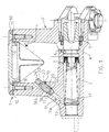
- Figure 1 is an axial section through a pump unit constructed in accordance with a first example of the present invention;
- Figures 2 and 3 are sectional views on a larger scale of two alternative embodiments of the same detail taken from the unit seen in Figure 1;
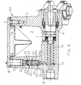
- Figure 4 is an axial section through a pump unit constructed in accordance with a second example of the present invention; and
- Figure 5 is a transverse section taken on V-V as marked in Figure 4 through the pump unit in an alternative embodiment.
- In Figures 1 to 3, the number 1 is an overall indication for a hydraulic pump unit for a vehicle, for instance a hydraulic brake pump unit for use on two-wheeled vehicles, motor cycles, snowmobiles and vehicles controlled via handlebars, or such like vehicles.
- The unit 1 comprises a
reservoir 2 containing the brake fluid and equipped with a pump having amaster cylinder 3 in which a floating piston 4, with a seal 5, slides leaktightly in an axial direction. The piston is pushed elastically towards a position of release or relaxation (shown in Figure 1) by aspring 12 acting between it and ashoulder 13 in themaster cylinder 3. - The
reservoir 2 communicates with themaster cylinder 3 through passages 6, 7 and is closed at its mouth 8 by a cover 9 that is fastened removably withscrews 10. A gasket 11 is provided between the mouth 8 of the reservoir and the cover 9. - A bleed circuit with the
general indication 15 runs between themaster cylinder 3 and thereservoir 2. - The bleed circuit comprises a
first length 16a which is cylindrical, has an approximately constant diameter, opens into the master cylinder in the vicinity of theshoulder 13 and ends in the opposite direction in aseating 17 for afrustoconical shutoff member 18 produced on an axial end of ableed nipple 19. Thenipple 19 can be screwed in and out in a threadedsecond length 16b of thebleed circuit 15, contains anaxial cavity 20 that divides up into first and secondradial passages head 23 containing ahexagonal sunken indentation 24 for turning by means of a key. - In the variants illustrated in Figures 2 and 3, the bleed nipples shown here and indicated by the
references head - In the
nipple 119, theaxial cavity 20 opens directly into the reservoir, whereas in thenipple 219 it is closed off and discharge into the reservoir is via theradial passage 22. - It will be observed, however, that the
bleed circuit 15 opens into thereservoir 2 at a substantially lower level than the normal operating level (L) of the brake fluid contained in the reservoir so that the outlet of thecircuit 15 is always submerged, during bleeding operations, in the aforementioned brake fluid. - It will also be observed that in the solutions envisaged the bleed nipple is accessible through the reservoir, and that the outlet of the circuit into the reservoir preferably does not point directly towards the mouth (or cover) in order to avoid brake fluid being ejected out of the reservoir during bleeding operations.
- Lastly, it will be observed that in the embodiment shown by way of example in Figure 1 the presence of a wrench in the
hexagonal sunken indentation 24 in thehead 23 will temporarily close theaxial cavity 20 at the reservoir end without the need for special arrangements for closing it off, as for example illustrated in Figure 3. - Figures 4 and 5 illustrate a second example of an embodiment of the invention in two variants indicated by the respective
general references - The
bleed nipple reservoir 2 but through ahole 30 formed in the thickness of one of thewalls 31 of thereservoir 2 and parallel to this wall. In thefirst variant 301 thehole 30 coincides with the hole for one of thescrews 10 used to secure the cover 9 and thebleed nipple 319 is accessible following removal of this screw but without the cover 9 having to be removed. In thesecond variant 401 thehole 30 is formed with an axis parallel to and spaced apart from thefixing screws 10 and is closed removably by the cover 9. In the latter case access to the bleed nipple requires that the cover 9 be taken off first. - In the solutions envisaged in Figures 3, 4 and 5, the
bleed nipple axial cavity 20 is closed by aball 33 forced into the end of thehexagonal sunken indentation 24, thus ensuring that the fluid escapes through the first and second radial passages or diametrical holes. - In the variants of Figures 4 and 5 the
bleed nipple ring 32 is provided between it and thehole 30 to prevent leakage out of thereservoir 2 along the bleed nipple. This serves to further prevent the risk of contamination of the brake fluid present in the reservoir. - In all cases air bleeding operations are carried out as follows.
- Having actuated the pump to pressurize the brake circuit, the bleed nipple is slackened off so that some of the brake fluid escapes through the bleed circuit into the reservoir, carrying any air bubbles with it in the process. Even if the cover 9 of the reservoir has been removed, as it must be in all the examples illustrated with the exception of that of Figure 4, no brake fluid will be ejected out of the reservoir because the small pressurized jet of fluid at the outlet of the bleed channel is not directed towards the mouth 8.
- The invention thus achieves numerous advantages over solutions offered in the prior art, including the following:
- it makes it unnecessary to connect the bleed nipple to a length of tubing and to the external container,
- it reduces, if not eliminates, the risk of contamination of the brake fluid during bleeding operations,
- it eliminates the risk of spillage of brake fluid in the environment during bleeding operations, thus reducing the risk of damage to the bodywork of the vehicle,
- the locating of the bleed nipple under the fluid level in the reservoir eliminates the risk of air re-entering the brake circuit should the bleed nipple be insufficiently tightened and allows a visual check of the escape, i.e. the bleeding, of the expelled air bubbles,
- the bleed nipple is protected and cannot be lost, takes up no space, creates no unsightly protrusions and necessitates no additional protection.
- In order to fulfil any particular needs that may arise, a person skilled in the art will be able to make numerous modifications, adaptations and substitutions of components with others of equivalent function, to the preferred embodiment of the pump unit described above, without however departing from the scope of the following claims.
Claims (11)
- Hydraulic pump unit (1) for a vehicle comprising a reservoir (2) for the brake fluid, a master cylinder (3) in the said pump connected to the said reservoir, and a bleed circuit (15) connected at one end to the said master cylinder and fitted with a bleed nipple (19, 119, 219, 319, 419) that is normally closed in order to shut the said circuit off, the said unit being characterized in that the said bleed circuit (15) is connected at the other end, downstream of the said bleed nipple (19, 119, 219, 319, 419), to the said reservoir (2).
- Pump unit (1), according to Claim 1, in which the said bleed circuit (15) opens into the said reservoir (2) at a substantially lower level than the normal operating level (L) of the said brake fluid in the said reservoir.
- Pump unit (1), according to Claim 1 or 2, in which the said reservoir (2) is provided with a mouth (8) that is removably closed by a cover (9), the said circuit being provided with an outlet into the said reservoir that does not point directly towards the said mouth.
- Pump unit (1), according to one or more of the preceding claims, in which the said bleed nipple (19, 119, 219) is accessible through the said reservoir.
- Pump unit (1), according to one or more of Claims 1 to 3, in which the said bleed nipple (319, 419) is accessible through a hole (30) formed in one of the walls (31) of the reservoir (2) and parallel thereto.
- Pump unit (1), according to Claim 5, in which the said hole (30) is closed removably by a screw (10) that serves as a fixing screw for the said cover.
- Pump unit (1), according to one or more of Claims 3 to 6, in which the bleed nipple (19, 219, 319, 419) has a shank containing an axial cavity (20) and the said outlet leads radially through the bleed nipple from the said axial cavity.
- Pump unit (1), according to Claim 7, in which the said bleed nipple (19, 319, 419) has a head (23) associated with the said shank containing an indentation (24) for a wrench.
- Pump unit (1), according to Claim 8, in which the said indentation (24) for a wrench is a sunken hexagon.
- Vehicle brake system comprising a pump unit (1) as defined in any one of the preceding claims.
- System for operating a vehicle friction clutch comprising a pump unit (1) as defined in any one of Claims 1 to 9.
Priority Applications (8)
| Application Number | Priority Date | Filing Date | Title |
|---|---|---|---|
| EP00830165A EP1129918B1 (en) | 2000-03-03 | 2000-03-03 | Hydraulic pump unit for vehicle |
| ES00830165T ES2306651T3 (en) | 2000-03-03 | 2000-03-03 | HYDRAULIC PUMP UNIT FOR VEHICLE. |
| DE60038865T DE60038865D1 (en) | 2000-03-03 | 2000-03-03 | Hydraulic pump unit for a vehicle |
| AT00830165T ATE395228T1 (en) | 2000-03-03 | 2000-03-03 | HYDRAULIC PUMP UNIT FOR A VEHICLE |
| US10/220,867 US6892536B2 (en) | 2000-03-03 | 2001-02-05 | Hydraulic pump unit for vehicle |
| JP2001563362A JP4880165B2 (en) | 2000-03-03 | 2001-02-05 | Hydraulic master cylinder for vehicle |
| PCT/EP2001/001180 WO2001064491A1 (en) | 2000-03-03 | 2001-02-05 | Hydraulic master cylinder for vehicle |
| AU2001240583A AU2001240583A1 (en) | 2000-03-03 | 2001-02-05 | Hydraulic master cylinder for vehicle |
Applications Claiming Priority (1)
| Application Number | Priority Date | Filing Date | Title |
|---|---|---|---|
| EP00830165A EP1129918B1 (en) | 2000-03-03 | 2000-03-03 | Hydraulic pump unit for vehicle |
Publications (2)
| Publication Number | Publication Date |
|---|---|
| EP1129918A1 true EP1129918A1 (en) | 2001-09-05 |
| EP1129918B1 EP1129918B1 (en) | 2008-05-14 |
Family
ID=8175224
Family Applications (1)
| Application Number | Title | Priority Date | Filing Date |
|---|---|---|---|
| EP00830165A Expired - Lifetime EP1129918B1 (en) | 2000-03-03 | 2000-03-03 | Hydraulic pump unit for vehicle |
Country Status (8)
| Country | Link |
|---|---|
| US (1) | US6892536B2 (en) |
| EP (1) | EP1129918B1 (en) |
| JP (1) | JP4880165B2 (en) |
| AT (1) | ATE395228T1 (en) |
| AU (1) | AU2001240583A1 (en) |
| DE (1) | DE60038865D1 (en) |
| ES (1) | ES2306651T3 (en) |
| WO (1) | WO2001064491A1 (en) |
Cited By (1)
| Publication number | Priority date | Publication date | Assignee | Title |
|---|---|---|---|---|
| WO2003093084A1 (en) * | 2002-04-30 | 2003-11-13 | Freni Brembo S.P.A. | Master cylinder unit for vehicles |
Families Citing this family (3)
| Publication number | Priority date | Publication date | Assignee | Title |
|---|---|---|---|---|
| IT201600103768A1 (en) * | 2016-10-17 | 2018-04-17 | Campagnolo Srl | Drain valve for hydraulic bicycle brake system |
| US10457265B2 (en) * | 2017-03-09 | 2019-10-29 | Ford Global Technologies, Llc | Methods and apparatus to facilitate brake bleeding |
| DE102021128118B3 (en) * | 2021-10-28 | 2022-11-24 | FAHRWERKER GmbH | hydraulic fitting |
Citations (2)
| Publication number | Priority date | Publication date | Assignee | Title |
|---|---|---|---|---|
| FR2538765A1 (en) * | 1982-12-30 | 1984-07-06 | Peugeot | Hydraulic device for controlling the braking or clutch engagement of a motor vehicle |
| US4971402A (en) * | 1989-09-12 | 1990-11-20 | Chen Teh Chih | Vehicle brake system with locking preventive mechanism |
Family Cites Families (9)
| Publication number | Priority date | Publication date | Assignee | Title |
|---|---|---|---|---|
| US2524544A (en) * | 1948-03-02 | 1950-10-03 | Harry T Seawell | Hydraulic brake bleeder system |
| US3247670A (en) * | 1964-03-23 | 1966-04-26 | Gen Motors Corp | Master cylinder with in-line compensating valve |
| US3559405A (en) * | 1969-03-20 | 1971-02-02 | Roger L Neilson | Self-bleeding, self-circulating braking system |
| JPS61111868A (en) * | 1984-11-06 | 1986-05-29 | Olympus Optical Co Ltd | Minutely feeding apparatus |
| JPS61111868U (en) * | 1984-12-27 | 1986-07-15 | ||
| JPS62189997A (en) * | 1986-02-12 | 1987-08-19 | Fuji Electric Co Ltd | Synchronous throwing-in control device of generator |
| JPH0355515Y2 (en) * | 1986-05-26 | 1991-12-10 | ||
| US5040816A (en) * | 1990-06-04 | 1991-08-20 | Unique Functional Products | Actuator/coupler |
| JPH09207752A (en) * | 1996-02-07 | 1997-08-12 | Nissin Kogyo Kk | Hydraulic master cylinder for vehicles |
-
2000
- 2000-03-03 AT AT00830165T patent/ATE395228T1/en not_active IP Right Cessation
- 2000-03-03 ES ES00830165T patent/ES2306651T3/en not_active Expired - Lifetime
- 2000-03-03 EP EP00830165A patent/EP1129918B1/en not_active Expired - Lifetime
- 2000-03-03 DE DE60038865T patent/DE60038865D1/en not_active Expired - Lifetime
-
2001
- 2001-02-05 AU AU2001240583A patent/AU2001240583A1/en not_active Abandoned
- 2001-02-05 JP JP2001563362A patent/JP4880165B2/en not_active Expired - Fee Related
- 2001-02-05 US US10/220,867 patent/US6892536B2/en not_active Expired - Fee Related
- 2001-02-05 WO PCT/EP2001/001180 patent/WO2001064491A1/en not_active Ceased
Patent Citations (2)
| Publication number | Priority date | Publication date | Assignee | Title |
|---|---|---|---|---|
| FR2538765A1 (en) * | 1982-12-30 | 1984-07-06 | Peugeot | Hydraulic device for controlling the braking or clutch engagement of a motor vehicle |
| US4971402A (en) * | 1989-09-12 | 1990-11-20 | Chen Teh Chih | Vehicle brake system with locking preventive mechanism |
Cited By (1)
| Publication number | Priority date | Publication date | Assignee | Title |
|---|---|---|---|---|
| WO2003093084A1 (en) * | 2002-04-30 | 2003-11-13 | Freni Brembo S.P.A. | Master cylinder unit for vehicles |
Also Published As
| Publication number | Publication date |
|---|---|
| US20030159440A1 (en) | 2003-08-28 |
| WO2001064491A1 (en) | 2001-09-07 |
| JP4880165B2 (en) | 2012-02-22 |
| JP2003525168A (en) | 2003-08-26 |
| ES2306651T3 (en) | 2008-11-16 |
| ATE395228T1 (en) | 2008-05-15 |
| AU2001240583A1 (en) | 2001-09-12 |
| EP1129918B1 (en) | 2008-05-14 |
| US6892536B2 (en) | 2005-05-17 |
| DE60038865D1 (en) | 2008-06-26 |
Similar Documents
| Publication | Publication Date | Title |
|---|---|---|
| US6302167B1 (en) | Apparatus and method for removing and replacing vehicular hydraulic fluid while flushing the hydraulic system | |
| US4834140A (en) | Brake bleeder valve | |
| EP1798126B1 (en) | Bleed screw for a bicycle brake device | |
| EP1129918B1 (en) | Hydraulic pump unit for vehicle | |
| US4989639A (en) | Brake bleeder check valve | |
| US6196364B1 (en) | Brake bleeder check valve | |
| GB2257216A (en) | Hydraulic braking systems | |
| US4445530A (en) | Corrosion protector for wheel brake assembly bleeder valve | |
| JP3970961B2 (en) | Non-functioning safety type hydraulic pressure relief / dump valve | |
| US4240191A (en) | Method and device for removing disc brake piston | |
| US6250447B1 (en) | Hydraulic operating system, particularly for a motorcycle brake and/or clutch | |
| US3298471A (en) | Valve for hydraulic brake holding system | |
| US4869292A (en) | Brake bleeder check valve | |
| US20090212249A1 (en) | Bleeding Screw Having a Kick-Back Valve | |
| US3318330A (en) | Tool for bleeding hydraulic brakes | |
| US4474272A (en) | Hydraulic brake cylinder fluid supply and bleeding mechanism | |
| US20040074722A1 (en) | Method for filling hydraulic apparatus with liquid, and apparatus thus filled | |
| EP0805086A3 (en) | Hydraulic pressure control apparatus having device for estimating amount of fluid in reservoir to which the fluid is discharged to reduce cylinder pressure | |
| CA1305643C (en) | Brake bleeder valve | |
| GR3004822T3 (en) | ||
| KR100337316B1 (en) | An air bleeding apparatus of abs mounted vehicles | |
| WO1999038744A1 (en) | Submersible brake actuator | |
| JP3056403U (en) | Automotive brake hydraulics | |
| KR100535456B1 (en) | Oil drain apparatus of oil pan | |
| KR101297567B1 (en) | Master Cylinder |
Legal Events
| Date | Code | Title | Description |
|---|---|---|---|
| PUAI | Public reference made under article 153(3) epc to a published international application that has entered the european phase |
Free format text: ORIGINAL CODE: 0009012 |
|
| AK | Designated contracting states |
Kind code of ref document: A1 Designated state(s): AT BE CH CY DE DK ES FI FR GB GR IE IT LI LU MC NL PT SE |
|
| AX | Request for extension of the european patent |
Free format text: AL;LT;LV;MK;RO;SI |
|
| 17P | Request for examination filed |
Effective date: 20020218 |
|
| AKX | Designation fees paid |
Free format text: AT BE CH CY DE DK ES FI FR GB GR IE IT LI LU MC NL PT SE |
|
| 17Q | First examination report despatched |
Effective date: 20050602 |
|
| GRAP | Despatch of communication of intention to grant a patent |
Free format text: ORIGINAL CODE: EPIDOSNIGR1 |
|
| GRAS | Grant fee paid |
Free format text: ORIGINAL CODE: EPIDOSNIGR3 |
|
| GRAA | (expected) grant |
Free format text: ORIGINAL CODE: 0009210 |
|
| AK | Designated contracting states |
Kind code of ref document: B1 Designated state(s): AT BE CH CY DE DK ES FI FR GB GR IE IT LI LU MC NL PT SE |
|
| REG | Reference to a national code |
Ref country code: GB Ref legal event code: FG4D |
|
| REG | Reference to a national code |
Ref country code: CH Ref legal event code: EP |
|
| REG | Reference to a national code |
Ref country code: IE Ref legal event code: FG4D Free format text: LANGUAGE OF EP DOCUMENT: FRENCH |
|
| REF | Corresponds to: |
Ref document number: 60038865 Country of ref document: DE Date of ref document: 20080626 Kind code of ref document: P |
|
| PG25 | Lapsed in a contracting state [announced via postgrant information from national office to epo] |
Ref country code: FI Free format text: LAPSE BECAUSE OF FAILURE TO SUBMIT A TRANSLATION OF THE DESCRIPTION OR TO PAY THE FEE WITHIN THE PRESCRIBED TIME-LIMIT Effective date: 20080514 |
|
| NLV1 | Nl: lapsed or annulled due to failure to fulfill the requirements of art. 29p and 29m of the patents act | ||
| REG | Reference to a national code |
Ref country code: ES Ref legal event code: FG2A Ref document number: 2306651 Country of ref document: ES Kind code of ref document: T3 |
|
| PG25 | Lapsed in a contracting state [announced via postgrant information from national office to epo] |
Ref country code: NL Free format text: LAPSE BECAUSE OF FAILURE TO SUBMIT A TRANSLATION OF THE DESCRIPTION OR TO PAY THE FEE WITHIN THE PRESCRIBED TIME-LIMIT Effective date: 20080514 Ref country code: AT Free format text: LAPSE BECAUSE OF FAILURE TO SUBMIT A TRANSLATION OF THE DESCRIPTION OR TO PAY THE FEE WITHIN THE PRESCRIBED TIME-LIMIT Effective date: 20080514 |
|
| PG25 | Lapsed in a contracting state [announced via postgrant information from national office to epo] |
Ref country code: SE Free format text: LAPSE BECAUSE OF FAILURE TO SUBMIT A TRANSLATION OF THE DESCRIPTION OR TO PAY THE FEE WITHIN THE PRESCRIBED TIME-LIMIT Effective date: 20080814 Ref country code: DK Free format text: LAPSE BECAUSE OF FAILURE TO SUBMIT A TRANSLATION OF THE DESCRIPTION OR TO PAY THE FEE WITHIN THE PRESCRIBED TIME-LIMIT Effective date: 20080514 Ref country code: PT Free format text: LAPSE BECAUSE OF FAILURE TO SUBMIT A TRANSLATION OF THE DESCRIPTION OR TO PAY THE FEE WITHIN THE PRESCRIBED TIME-LIMIT Effective date: 20081014 |
|
| PG25 | Lapsed in a contracting state [announced via postgrant information from national office to epo] |
Ref country code: BE Free format text: LAPSE BECAUSE OF FAILURE TO SUBMIT A TRANSLATION OF THE DESCRIPTION OR TO PAY THE FEE WITHIN THE PRESCRIBED TIME-LIMIT Effective date: 20080514 |
|
| PLBE | No opposition filed within time limit |
Free format text: ORIGINAL CODE: 0009261 |
|
| STAA | Information on the status of an ep patent application or granted ep patent |
Free format text: STATUS: NO OPPOSITION FILED WITHIN TIME LIMIT |
|
| 26N | No opposition filed |
Effective date: 20090217 |
|
| PG25 | Lapsed in a contracting state [announced via postgrant information from national office to epo] |
Ref country code: MC Free format text: LAPSE BECAUSE OF NON-PAYMENT OF DUE FEES Effective date: 20090331 |
|
| REG | Reference to a national code |
Ref country code: CH Ref legal event code: PL |
|
| REG | Reference to a national code |
Ref country code: FR Ref legal event code: ST Effective date: 20091130 |
|
| REG | Reference to a national code |
Ref country code: IE Ref legal event code: MM4A |
|
| PG25 | Lapsed in a contracting state [announced via postgrant information from national office to epo] |
Ref country code: CH Free format text: LAPSE BECAUSE OF NON-PAYMENT OF DUE FEES Effective date: 20090331 Ref country code: IE Free format text: LAPSE BECAUSE OF NON-PAYMENT OF DUE FEES Effective date: 20090303 Ref country code: LI Free format text: LAPSE BECAUSE OF NON-PAYMENT OF DUE FEES Effective date: 20090331 |
|
| PG25 | Lapsed in a contracting state [announced via postgrant information from national office to epo] |
Ref country code: FR Free format text: LAPSE BECAUSE OF NON-PAYMENT OF DUE FEES Effective date: 20091123 |
|
| PG25 | Lapsed in a contracting state [announced via postgrant information from national office to epo] |
Ref country code: GR Free format text: LAPSE BECAUSE OF FAILURE TO SUBMIT A TRANSLATION OF THE DESCRIPTION OR TO PAY THE FEE WITHIN THE PRESCRIBED TIME-LIMIT Effective date: 20080815 |
|
| PG25 | Lapsed in a contracting state [announced via postgrant information from national office to epo] |
Ref country code: LU Free format text: LAPSE BECAUSE OF NON-PAYMENT OF DUE FEES Effective date: 20090303 |
|
| PG25 | Lapsed in a contracting state [announced via postgrant information from national office to epo] |
Ref country code: CY Free format text: LAPSE BECAUSE OF FAILURE TO SUBMIT A TRANSLATION OF THE DESCRIPTION OR TO PAY THE FEE WITHIN THE PRESCRIBED TIME-LIMIT Effective date: 20080514 |
|
| PGFP | Annual fee paid to national office [announced via postgrant information from national office to epo] |
Ref country code: ES Payment date: 20120320 Year of fee payment: 13 |
|
| REG | Reference to a national code |
Ref country code: ES Ref legal event code: FD2A Effective date: 20140611 |
|
| PG25 | Lapsed in a contracting state [announced via postgrant information from national office to epo] |
Ref country code: ES Free format text: LAPSE BECAUSE OF NON-PAYMENT OF DUE FEES Effective date: 20130304 |
|
| PGFP | Annual fee paid to national office [announced via postgrant information from national office to epo] |
Ref country code: GB Payment date: 20150319 Year of fee payment: 16 |
|
| PGFP | Annual fee paid to national office [announced via postgrant information from national office to epo] |
Ref country code: DE Payment date: 20150601 Year of fee payment: 16 |
|
| REG | Reference to a national code |
Ref country code: DE Ref legal event code: R119 Ref document number: 60038865 Country of ref document: DE |
|
| GBPC | Gb: european patent ceased through non-payment of renewal fee |
Effective date: 20160303 |
|
| PG25 | Lapsed in a contracting state [announced via postgrant information from national office to epo] |
Ref country code: DE Free format text: LAPSE BECAUSE OF NON-PAYMENT OF DUE FEES Effective date: 20161001 Ref country code: GB Free format text: LAPSE BECAUSE OF NON-PAYMENT OF DUE FEES Effective date: 20160303 |
|
| PGFP | Annual fee paid to national office [announced via postgrant information from national office to epo] |
Ref country code: IT Payment date: 20190311 Year of fee payment: 20 |