EP1129889A2 - Regeneration control device of hybrid electric vehicle - Google Patents
Regeneration control device of hybrid electric vehicle Download PDFInfo
- Publication number
- EP1129889A2 EP1129889A2 EP01104361A EP01104361A EP1129889A2 EP 1129889 A2 EP1129889 A2 EP 1129889A2 EP 01104361 A EP01104361 A EP 01104361A EP 01104361 A EP01104361 A EP 01104361A EP 1129889 A2 EP1129889 A2 EP 1129889A2
- Authority
- EP
- European Patent Office
- Prior art keywords
- power
- engine
- regenerated
- battery
- generator
- Prior art date
- Legal status (The legal status is an assumption and is not a legal conclusion. Google has not performed a legal analysis and makes no representation as to the accuracy of the status listed.)
- Granted
Links
Images


Classifications
-
- B—PERFORMING OPERATIONS; TRANSPORTING
- B60—VEHICLES IN GENERAL
- B60L—PROPULSION OF ELECTRICALLY-PROPELLED VEHICLES; SUPPLYING ELECTRIC POWER FOR AUXILIARY EQUIPMENT OF ELECTRICALLY-PROPELLED VEHICLES; ELECTRODYNAMIC BRAKE SYSTEMS FOR VEHICLES IN GENERAL; MAGNETIC SUSPENSION OR LEVITATION FOR VEHICLES; MONITORING OPERATING VARIABLES OF ELECTRICALLY-PROPELLED VEHICLES; ELECTRIC SAFETY DEVICES FOR ELECTRICALLY-PROPELLED VEHICLES
- B60L7/00—Electrodynamic brake systems for vehicles in general
- B60L7/22—Dynamic electric resistor braking, combined with dynamic electric regenerative braking
-
- B—PERFORMING OPERATIONS; TRANSPORTING
- B60—VEHICLES IN GENERAL
- B60W—CONJOINT CONTROL OF VEHICLE SUB-UNITS OF DIFFERENT TYPE OR DIFFERENT FUNCTION; CONTROL SYSTEMS SPECIALLY ADAPTED FOR HYBRID VEHICLES; ROAD VEHICLE DRIVE CONTROL SYSTEMS FOR PURPOSES NOT RELATED TO THE CONTROL OF A PARTICULAR SUB-UNIT
- B60W20/00—Control systems specially adapted for hybrid vehicles
- B60W20/10—Controlling the power contribution of each of the prime movers to meet required power demand
- B60W20/13—Controlling the power contribution of each of the prime movers to meet required power demand in order to stay within battery power input or output limits; in order to prevent overcharging or battery depletion
-
- B—PERFORMING OPERATIONS; TRANSPORTING
- B60—VEHICLES IN GENERAL
- B60K—ARRANGEMENT OR MOUNTING OF PROPULSION UNITS OR OF TRANSMISSIONS IN VEHICLES; ARRANGEMENT OR MOUNTING OF PLURAL DIVERSE PRIME-MOVERS IN VEHICLES; AUXILIARY DRIVES FOR VEHICLES; INSTRUMENTATION OR DASHBOARDS FOR VEHICLES; ARRANGEMENTS IN CONNECTION WITH COOLING, AIR INTAKE, GAS EXHAUST OR FUEL SUPPLY OF PROPULSION UNITS IN VEHICLES
- B60K6/00—Arrangement or mounting of plural diverse prime-movers for mutual or common propulsion, e.g. hybrid propulsion systems comprising electric motors and internal combustion engines
- B60K6/20—Arrangement or mounting of plural diverse prime-movers for mutual or common propulsion, e.g. hybrid propulsion systems comprising electric motors and internal combustion engines the prime-movers consisting of electric motors and internal combustion engines, e.g. HEVs
- B60K6/42—Arrangement or mounting of plural diverse prime-movers for mutual or common propulsion, e.g. hybrid propulsion systems comprising electric motors and internal combustion engines the prime-movers consisting of electric motors and internal combustion engines, e.g. HEVs characterised by the architecture of the hybrid electric vehicle
- B60K6/46—Series type
-
- B—PERFORMING OPERATIONS; TRANSPORTING
- B60—VEHICLES IN GENERAL
- B60L—PROPULSION OF ELECTRICALLY-PROPELLED VEHICLES; SUPPLYING ELECTRIC POWER FOR AUXILIARY EQUIPMENT OF ELECTRICALLY-PROPELLED VEHICLES; ELECTRODYNAMIC BRAKE SYSTEMS FOR VEHICLES IN GENERAL; MAGNETIC SUSPENSION OR LEVITATION FOR VEHICLES; MONITORING OPERATING VARIABLES OF ELECTRICALLY-PROPELLED VEHICLES; ELECTRIC SAFETY DEVICES FOR ELECTRICALLY-PROPELLED VEHICLES
- B60L15/00—Methods, circuits, or devices for controlling the traction-motor speed of electrically-propelled vehicles
- B60L15/20—Methods, circuits, or devices for controlling the traction-motor speed of electrically-propelled vehicles for control of the vehicle or its driving motor to achieve a desired performance, e.g. speed, torque, programmed variation of speed
- B60L15/2009—Methods, circuits, or devices for controlling the traction-motor speed of electrically-propelled vehicles for control of the vehicle or its driving motor to achieve a desired performance, e.g. speed, torque, programmed variation of speed for braking
-
- B—PERFORMING OPERATIONS; TRANSPORTING
- B60—VEHICLES IN GENERAL
- B60L—PROPULSION OF ELECTRICALLY-PROPELLED VEHICLES; SUPPLYING ELECTRIC POWER FOR AUXILIARY EQUIPMENT OF ELECTRICALLY-PROPELLED VEHICLES; ELECTRODYNAMIC BRAKE SYSTEMS FOR VEHICLES IN GENERAL; MAGNETIC SUSPENSION OR LEVITATION FOR VEHICLES; MONITORING OPERATING VARIABLES OF ELECTRICALLY-PROPELLED VEHICLES; ELECTRIC SAFETY DEVICES FOR ELECTRICALLY-PROPELLED VEHICLES
- B60L50/00—Electric propulsion with power supplied within the vehicle
- B60L50/50—Electric propulsion with power supplied within the vehicle using propulsion power supplied by batteries or fuel cells
- B60L50/60—Electric propulsion with power supplied within the vehicle using propulsion power supplied by batteries or fuel cells using power supplied by batteries
- B60L50/61—Electric propulsion with power supplied within the vehicle using propulsion power supplied by batteries or fuel cells using power supplied by batteries by batteries charged by engine-driven generators, e.g. series hybrid electric vehicles
-
- B—PERFORMING OPERATIONS; TRANSPORTING
- B60—VEHICLES IN GENERAL
- B60L—PROPULSION OF ELECTRICALLY-PROPELLED VEHICLES; SUPPLYING ELECTRIC POWER FOR AUXILIARY EQUIPMENT OF ELECTRICALLY-PROPELLED VEHICLES; ELECTRODYNAMIC BRAKE SYSTEMS FOR VEHICLES IN GENERAL; MAGNETIC SUSPENSION OR LEVITATION FOR VEHICLES; MONITORING OPERATING VARIABLES OF ELECTRICALLY-PROPELLED VEHICLES; ELECTRIC SAFETY DEVICES FOR ELECTRICALLY-PROPELLED VEHICLES
- B60L7/00—Electrodynamic brake systems for vehicles in general
- B60L7/20—Braking by supplying regenerated power to the prime mover of vehicles comprising engine-driven generators
-
- B—PERFORMING OPERATIONS; TRANSPORTING
- B60—VEHICLES IN GENERAL
- B60W—CONJOINT CONTROL OF VEHICLE SUB-UNITS OF DIFFERENT TYPE OR DIFFERENT FUNCTION; CONTROL SYSTEMS SPECIALLY ADAPTED FOR HYBRID VEHICLES; ROAD VEHICLE DRIVE CONTROL SYSTEMS FOR PURPOSES NOT RELATED TO THE CONTROL OF A PARTICULAR SUB-UNIT
- B60W10/00—Conjoint control of vehicle sub-units of different type or different function
- B60W10/04—Conjoint control of vehicle sub-units of different type or different function including control of propulsion units
- B60W10/06—Conjoint control of vehicle sub-units of different type or different function including control of propulsion units including control of combustion engines
-
- B—PERFORMING OPERATIONS; TRANSPORTING
- B60—VEHICLES IN GENERAL
- B60W—CONJOINT CONTROL OF VEHICLE SUB-UNITS OF DIFFERENT TYPE OR DIFFERENT FUNCTION; CONTROL SYSTEMS SPECIALLY ADAPTED FOR HYBRID VEHICLES; ROAD VEHICLE DRIVE CONTROL SYSTEMS FOR PURPOSES NOT RELATED TO THE CONTROL OF A PARTICULAR SUB-UNIT
- B60W10/00—Conjoint control of vehicle sub-units of different type or different function
- B60W10/04—Conjoint control of vehicle sub-units of different type or different function including control of propulsion units
- B60W10/08—Conjoint control of vehicle sub-units of different type or different function including control of propulsion units including control of electric propulsion units, e.g. motors or generators
-
- B—PERFORMING OPERATIONS; TRANSPORTING
- B60—VEHICLES IN GENERAL
- B60W—CONJOINT CONTROL OF VEHICLE SUB-UNITS OF DIFFERENT TYPE OR DIFFERENT FUNCTION; CONTROL SYSTEMS SPECIALLY ADAPTED FOR HYBRID VEHICLES; ROAD VEHICLE DRIVE CONTROL SYSTEMS FOR PURPOSES NOT RELATED TO THE CONTROL OF A PARTICULAR SUB-UNIT
- B60W10/00—Conjoint control of vehicle sub-units of different type or different function
- B60W10/18—Conjoint control of vehicle sub-units of different type or different function including control of braking systems
-
- B—PERFORMING OPERATIONS; TRANSPORTING
- B60—VEHICLES IN GENERAL
- B60W—CONJOINT CONTROL OF VEHICLE SUB-UNITS OF DIFFERENT TYPE OR DIFFERENT FUNCTION; CONTROL SYSTEMS SPECIALLY ADAPTED FOR HYBRID VEHICLES; ROAD VEHICLE DRIVE CONTROL SYSTEMS FOR PURPOSES NOT RELATED TO THE CONTROL OF A PARTICULAR SUB-UNIT
- B60W10/00—Conjoint control of vehicle sub-units of different type or different function
- B60W10/24—Conjoint control of vehicle sub-units of different type or different function including control of energy storage means
- B60W10/26—Conjoint control of vehicle sub-units of different type or different function including control of energy storage means for electrical energy, e.g. batteries or capacitors
-
- B—PERFORMING OPERATIONS; TRANSPORTING
- B60—VEHICLES IN GENERAL
- B60W—CONJOINT CONTROL OF VEHICLE SUB-UNITS OF DIFFERENT TYPE OR DIFFERENT FUNCTION; CONTROL SYSTEMS SPECIALLY ADAPTED FOR HYBRID VEHICLES; ROAD VEHICLE DRIVE CONTROL SYSTEMS FOR PURPOSES NOT RELATED TO THE CONTROL OF A PARTICULAR SUB-UNIT
- B60W20/00—Control systems specially adapted for hybrid vehicles
-
- B—PERFORMING OPERATIONS; TRANSPORTING
- B60—VEHICLES IN GENERAL
- B60W—CONJOINT CONTROL OF VEHICLE SUB-UNITS OF DIFFERENT TYPE OR DIFFERENT FUNCTION; CONTROL SYSTEMS SPECIALLY ADAPTED FOR HYBRID VEHICLES; ROAD VEHICLE DRIVE CONTROL SYSTEMS FOR PURPOSES NOT RELATED TO THE CONTROL OF A PARTICULAR SUB-UNIT
- B60W30/00—Purposes of road vehicle drive control systems not related to the control of a particular sub-unit, e.g. of systems using conjoint control of vehicle sub-units
- B60W30/18—Propelling the vehicle
- B60W30/18009—Propelling the vehicle related to particular drive situations
- B60W30/18109—Braking
-
- B—PERFORMING OPERATIONS; TRANSPORTING
- B60—VEHICLES IN GENERAL
- B60L—PROPULSION OF ELECTRICALLY-PROPELLED VEHICLES; SUPPLYING ELECTRIC POWER FOR AUXILIARY EQUIPMENT OF ELECTRICALLY-PROPELLED VEHICLES; ELECTRODYNAMIC BRAKE SYSTEMS FOR VEHICLES IN GENERAL; MAGNETIC SUSPENSION OR LEVITATION FOR VEHICLES; MONITORING OPERATING VARIABLES OF ELECTRICALLY-PROPELLED VEHICLES; ELECTRIC SAFETY DEVICES FOR ELECTRICALLY-PROPELLED VEHICLES
- B60L2210/00—Converter types
- B60L2210/40—DC to AC converters
-
- B—PERFORMING OPERATIONS; TRANSPORTING
- B60—VEHICLES IN GENERAL
- B60L—PROPULSION OF ELECTRICALLY-PROPELLED VEHICLES; SUPPLYING ELECTRIC POWER FOR AUXILIARY EQUIPMENT OF ELECTRICALLY-PROPELLED VEHICLES; ELECTRODYNAMIC BRAKE SYSTEMS FOR VEHICLES IN GENERAL; MAGNETIC SUSPENSION OR LEVITATION FOR VEHICLES; MONITORING OPERATING VARIABLES OF ELECTRICALLY-PROPELLED VEHICLES; ELECTRIC SAFETY DEVICES FOR ELECTRICALLY-PROPELLED VEHICLES
- B60L2240/00—Control parameters of input or output; Target parameters
- B60L2240/40—Drive Train control parameters
- B60L2240/42—Drive Train control parameters related to electric machines
- B60L2240/423—Torque
-
- Y—GENERAL TAGGING OF NEW TECHNOLOGICAL DEVELOPMENTS; GENERAL TAGGING OF CROSS-SECTIONAL TECHNOLOGIES SPANNING OVER SEVERAL SECTIONS OF THE IPC; TECHNICAL SUBJECTS COVERED BY FORMER USPC CROSS-REFERENCE ART COLLECTIONS [XRACs] AND DIGESTS
- Y02—TECHNOLOGIES OR APPLICATIONS FOR MITIGATION OR ADAPTATION AGAINST CLIMATE CHANGE
- Y02T—CLIMATE CHANGE MITIGATION TECHNOLOGIES RELATED TO TRANSPORTATION
- Y02T10/00—Road transport of goods or passengers
- Y02T10/60—Other road transportation technologies with climate change mitigation effect
- Y02T10/62—Hybrid vehicles
-
- Y—GENERAL TAGGING OF NEW TECHNOLOGICAL DEVELOPMENTS; GENERAL TAGGING OF CROSS-SECTIONAL TECHNOLOGIES SPANNING OVER SEVERAL SECTIONS OF THE IPC; TECHNICAL SUBJECTS COVERED BY FORMER USPC CROSS-REFERENCE ART COLLECTIONS [XRACs] AND DIGESTS
- Y02—TECHNOLOGIES OR APPLICATIONS FOR MITIGATION OR ADAPTATION AGAINST CLIMATE CHANGE
- Y02T—CLIMATE CHANGE MITIGATION TECHNOLOGIES RELATED TO TRANSPORTATION
- Y02T10/00—Road transport of goods or passengers
- Y02T10/60—Other road transportation technologies with climate change mitigation effect
- Y02T10/64—Electric machine technologies in electromobility
-
- Y—GENERAL TAGGING OF NEW TECHNOLOGICAL DEVELOPMENTS; GENERAL TAGGING OF CROSS-SECTIONAL TECHNOLOGIES SPANNING OVER SEVERAL SECTIONS OF THE IPC; TECHNICAL SUBJECTS COVERED BY FORMER USPC CROSS-REFERENCE ART COLLECTIONS [XRACs] AND DIGESTS
- Y02—TECHNOLOGIES OR APPLICATIONS FOR MITIGATION OR ADAPTATION AGAINST CLIMATE CHANGE
- Y02T—CLIMATE CHANGE MITIGATION TECHNOLOGIES RELATED TO TRANSPORTATION
- Y02T10/00—Road transport of goods or passengers
- Y02T10/60—Other road transportation technologies with climate change mitigation effect
- Y02T10/70—Energy storage systems for electromobility, e.g. batteries
-
- Y—GENERAL TAGGING OF NEW TECHNOLOGICAL DEVELOPMENTS; GENERAL TAGGING OF CROSS-SECTIONAL TECHNOLOGIES SPANNING OVER SEVERAL SECTIONS OF THE IPC; TECHNICAL SUBJECTS COVERED BY FORMER USPC CROSS-REFERENCE ART COLLECTIONS [XRACs] AND DIGESTS
- Y02—TECHNOLOGIES OR APPLICATIONS FOR MITIGATION OR ADAPTATION AGAINST CLIMATE CHANGE
- Y02T—CLIMATE CHANGE MITIGATION TECHNOLOGIES RELATED TO TRANSPORTATION
- Y02T10/00—Road transport of goods or passengers
- Y02T10/60—Other road transportation technologies with climate change mitigation effect
- Y02T10/7072—Electromobility specific charging systems or methods for batteries, ultracapacitors, supercapacitors or double-layer capacitors
-
- Y—GENERAL TAGGING OF NEW TECHNOLOGICAL DEVELOPMENTS; GENERAL TAGGING OF CROSS-SECTIONAL TECHNOLOGIES SPANNING OVER SEVERAL SECTIONS OF THE IPC; TECHNICAL SUBJECTS COVERED BY FORMER USPC CROSS-REFERENCE ART COLLECTIONS [XRACs] AND DIGESTS
- Y02—TECHNOLOGIES OR APPLICATIONS FOR MITIGATION OR ADAPTATION AGAINST CLIMATE CHANGE
- Y02T—CLIMATE CHANGE MITIGATION TECHNOLOGIES RELATED TO TRANSPORTATION
- Y02T10/00—Road transport of goods or passengers
- Y02T10/60—Other road transportation technologies with climate change mitigation effect
- Y02T10/72—Electric energy management in electromobility
-
- Y—GENERAL TAGGING OF NEW TECHNOLOGICAL DEVELOPMENTS; GENERAL TAGGING OF CROSS-SECTIONAL TECHNOLOGIES SPANNING OVER SEVERAL SECTIONS OF THE IPC; TECHNICAL SUBJECTS COVERED BY FORMER USPC CROSS-REFERENCE ART COLLECTIONS [XRACs] AND DIGESTS
- Y10—TECHNICAL SUBJECTS COVERED BY FORMER USPC
- Y10S—TECHNICAL SUBJECTS COVERED BY FORMER USPC CROSS-REFERENCE ART COLLECTIONS [XRACs] AND DIGESTS
- Y10S903/00—Hybrid electric vehicles, HEVS
- Y10S903/902—Prime movers comprising electrical and internal combustion motors
- Y10S903/903—Prime movers comprising electrical and internal combustion motors having energy storing means, e.g. battery, capacitor
-
- Y—GENERAL TAGGING OF NEW TECHNOLOGICAL DEVELOPMENTS; GENERAL TAGGING OF CROSS-SECTIONAL TECHNOLOGIES SPANNING OVER SEVERAL SECTIONS OF THE IPC; TECHNICAL SUBJECTS COVERED BY FORMER USPC CROSS-REFERENCE ART COLLECTIONS [XRACs] AND DIGESTS
- Y10—TECHNICAL SUBJECTS COVERED BY FORMER USPC
- Y10S—TECHNICAL SUBJECTS COVERED BY FORMER USPC CROSS-REFERENCE ART COLLECTIONS [XRACs] AND DIGESTS
- Y10S903/00—Hybrid electric vehicles, HEVS
- Y10S903/902—Prime movers comprising electrical and internal combustion motors
- Y10S903/903—Prime movers comprising electrical and internal combustion motors having energy storing means, e.g. battery, capacitor
- Y10S903/947—Characterized by control of braking, e.g. blending of regeneration, friction braking
Definitions
- the present invention generally relates to a hybrid electric vehicle, and more particularly to a generation control technique for a hybrid electric vehicle.
- a series hybrid vehicle that is a vehicle equipped with a motor as a source of driving force for the vehicle and charges a secondary battery, which supplies power to the motor, by a generator driven by a relatively-small engine.
- the power from driving wheels runs the motor to generate a braking force when the vehicle is braked.
- the power generated by the motor is utilized as regeneration energy to enable a so-called regenerative braking.
- the power acquired by the regenerative braking is normally charged in the battery.
- Japanese Patent Provisional Publication No. 7-131905 discloses a device, which supplies the surplus generated power to a generator to operate the generator when the regenerated power acquired by the regenerative braking is in excess of an allowable charging level of the battery, and therefore forcibly runs an engine to run an engine brake by using the power generated by the regenerative braking.
- the device disclosed in the above publication operates the generator to run the engine brake when the generated power exceeds the allowable charging level of the battery.
- the battery is charged until the charging level becomes a full charge regardless of the supplied power if the charging level has not yet reached the full charge.
- the chargeable power varies according to the charging level of the battery.
- the battery can only be charged with the chargeable power even if the battery has an extra chargeable capacity in view of its charging level.
- the braking force in the regenerative braking is not determined for the purpose of charging the battery, but is determined according to a deceleration required by a driver.
- the regenerated power, which is actually generated by the motor, is directly influenced by a deceleration torque corresponding to the deceleration. The larger the deceleration torque is, the more the regenerated power is.
- the generator is operated according to the charging level of the battery to run the engine brake, it is determined that the battery has an extra chargeable capacity in view of the charging level on condition that the regenerated power is not greater than the allowable charging level of the battery, even when the regenerated power is in excess of the chargeable power when the driver wants to suddenly brake the vehicle. Therefore, the generator is not operated and the engine brake is not run. This decreases the power generated by the motor, and increases the number of times at which the friction brake is used. This accelerates the wear of a friction material, and may deteriorate the durability of the friction brake.
- a hybrid electric vehicle comprising: a generator being rotated by a driving force of an engine to thereby generate power; a battery for charging the power generated by the generator; a motor for generating a driving force for a vehicle by the power supplied from the battery and regenerating energy by using power from driving wheels to generate power and charge the battery when the vehicle is braked; a charging level sensing device for sensing a charging level of the battery; a chargeable power setting device for setting chargeable power in accordance with a sensed value of the charging level sensing device; a deceleration instruction device for instructing the vehicle to decelerate; a deceleration torque sensing device for sensing a deceleration torque required by the deceleration instruction device; a regenerated power computing unit for setting regenerated power to be regenerated by the motor according to a sensed value of the deceleration torque sensing device; and a control device for supplying the power generated by the motor to the generator to thereby drive the generator to run
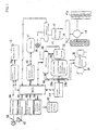
- Fig. 1 is a schematic block diagram showing a series hybrid vehicle, to which a regeneration control device of a hybrid electric vehicle according to the present invention is applied.
- a regeneration control device of a hybrid electric vehicle according to the present invention is applied.
- a large vehicle such as an omnibus, which runs at a low speed in a city, is supposed to be the series hybrid vehicle.
- the series hybrid vehicle is equipped with a traction motor 10 as a source of driving force.
- the traction motor 10 is electrically connected to a high-voltage secondary battery 12, which is used for running the traction motor 10, through an inverter 14.
- the traction motor 10 is, e.g., an induction motor, but may also be a permanent electromagnet synchronous type motor.
- the traction motor 10 When the vehicle is braked, the traction motor 10 also functions as an energy regenerative brake (regenerative braking), i.e., a generator that utilizes braking energy. More specifically, when a driver of the vehicle operates a brake pedal 58, the traction motor 10 generates a braking force and power at the same time. The generated power is charged in the battery 12.
- regenerative braking energy regenerative brake
- the inverter 14 supplies stable power to the traction motor 10 by adjusting a voltage and a current supplied from the battery 12 or a later-described generator 22, or supplies stable power to the battery 12 by adjusting a voltage and a current generated by the traction motor 10.
- a pair of driving wheels WR, WL is connected to a rotary shaft of the traction motor 10 through reduction gears 16 and differential gears 18.
- the reduction gears 16 should not necessarily be provided.
- the battery 12 and the inverter 14 are electrically connected to the generator 22 through the other inverter 20.
- a rotary shaft of the generator 22 is connected to an output shaft of an engine 24, which is an internal combustion engine for generator.
- the engine 24 is an internal combustion engine for exclusive use in generation. If surplus power, which cannot be charged in the battery 12, is generated during the regenerating operation of the traction motor 10, the surplus power drives the generator 22 to forcibly run the engine 24 without the supply of fuel so that the surplus power can be consumed as an engine brake.
- An exhaust system of the engine 24 has auxiliary braking devices such as an exhaust brake (an exhaust BRK) 24a for generating a braking force by restricting the flow of exhaust, and a compression pressure opening type brake (a compression pressure opening BRK) 24b for forcibly opening the air compressed by a piston in a cylinder in order to use a compressing work as a braking force.
- an exhaust brake an exhaust BRK
- a compression pressure opening type brake a compression pressure opening BRK
- the inverter 20 is also electrically connected to an auxiliary motor 26, which drives auxiliaries such as an air compressor 27 for an air brake and a power steering pump 28.
- auxiliaries such as an air compressor 27 for an air brake and a power steering pump 28.
- the inverter 20 supplies stable power to the battery 12 or the traction motor 10 by adjusting a voltage and a current generated by the generator 22, or supplies stable power to the auxiliary motor 26 by adjusting the voltage and the current from the battery 12.
- a relay fuse 30 is mounted between the battery 12 and the inverters 14, 20.
- the relay fuse 30 is electrically connected to the inverter 14.
- the relay fuse 30 allows a current to flow from the battery 12 to the traction motor 10, prevents an excessive current from flowing from the battery 12 to the traction motor 10 in accordance with information from the inverter 14, or prevents the generator 22 or traction motor 10 during the regenerative braking (the engine regeneration) from excessively charging the battery 12.
- the battery 12 and the inverters 14, 20 are electrically connected to an electronic control unit (ECU) 40 so that the battery 12 and the inverter 14, 20 can communicate with the ECU 40.
- the inverter 14 and the inverter 20 are electrically connected to the traction motor 10 and the generator 22, respectively, so that they can communicate with one another.
- the receiving side of the ECU 40 is connected to an accelerator pedal 50, which transmits one output requirement from the driver, i.e., a required motor torque to the traction motor 10.
- the receiving side of the ECU 40 is also connected to an acceleration sensor 44, which senses a control input ⁇ acc of the accelerator pedal 43, and a vehicle speed sensor 46, which senses a vehicle speed 46.
- the vehicle speed sensor 46 is, for example, a vehicle wheel speed sensor that senses the vehicle speed V according to vehicle wheel speed information.
- the output side of the ECU 40 is connected to a display/alerting device 52 through a display/alerting controller 50.
- the ECU 40 is also connected to a brake controller 54, which controls the braking of the vehicle by supplying a drive signal to a brake unit (service brake) 56.
- the brake controller 54 is connected to a brake sensor 60, which senses a control input (e.g., a brake pedal stroke) of the brake pedal 58.
- the ECU 40 is also connected to a battery controller (charging level sensing device) 62, which monitors a charging level (SOC: state of charge), etc. of the battery 12, and an engine controller 64, which controls the operation of the engine 24 and controls the operation of the exhaust brake 24a and the compression pressure opening type brake 24b.
- the engine controller 64 is capable of sensing an engine revolution speed.
- the ECU 40 has a chargeable power setting device 71 for setting chargeable power according to the charging level sensed by the battery controller 62, a deceleration torque sensing device 73 for sensing a deceleration torque required by a driver according to the output of the brake sensor 60 or the acceleration sensor 44, a regenerated power computing unit 75 for calculating regenerated power regenerated by the traction motor 60 according to the deceleration torque sensed by the deceleration torque sensing device 73 or the brake controller 54, and a control unit 77 of each device for controlling the entire system of the present invention.
- a chargeable power setting device 71 for setting chargeable power according to the charging level sensed by the battery controller 62
- a deceleration torque sensing device 73 for sensing a deceleration torque required by a driver according to the output of the brake sensor 60 or the acceleration sensor 44
- a regenerated power computing unit 75 for calculating regenerated power regenerated by the traction motor 60 according to the deceleration
- the accelerator pedal 43 or the brake pedal 58 functions as a deceleration instruction device.
- a required motor torque signal corresponding to the control input ⁇ acc of the accelerator pedal 50 is supplied to the inverter 14 while the vehicle is running.
- the inverter 14 adjusts the voltage and the current from the battery 12, and therefore, the traction motor 10 generates a desired motor torque.
- the battery controller 46 senses a drop in the charging level (SOC) of the battery 12
- the engine controller 48 starts the engine 24 to operate the generator 22, which generates power to charge the battery 12 in accordance with the SOC. If the SOC of the battery 12 is low, the power corresponding to the power consumption of the traction motor 10 is directly supplied from the generator 22 to the traction motor 10. The surplus power generated by the generator 22 is charged in the battery 12.
- the traction motor 10 performs the regenerative braking and generates power.
- the regenerated power charges the battery 12.
- the regenerated power drives the generator 22 to forcibly operates the engine 24 without the supply of fuel and consume the regenerated power as an engine brake.
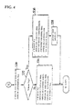
- Figs. 3 and 4 are flow charts showing a regeneration control routine executed by the ECU 40 according to the present invention. The operation of the regeneration control device will be described with reference to the flow charts of Figs. 3 and 4.
- a step S10 is executed by the chargeable power setting device 71
- a step S11 is executed by the deceleration torque sensing device 73
- a step S12 is executed by the regenerated power computing unit 75
- a step 14 and the succeeding steps are executed by the control devices 77.
- the deceleration torque Tbrk is computed according to the control input ⁇ acc of the accelerator pedal 43 sensed by the acceleration sensor 44, the control input of the brake pedal 58 sensed by the brake sensor 60, and the like.
- the process then goes to the step S14.
- the chargeable power Prc is compared with the regenerated power Pr to determine whether the regenerated power Pr is in excess of the chargeable power Prc (Prc ⁇ Pr). More specifically, whether the regenerated power Pr exceeds the chargeable power or not is determined by using the chargeable power Prc as a threshold level. The chargeable power Prc varies according to the charging level. The process goes to a step S16 if the determination result is NO, i.e., the regenerated power Pr is not greater than the chargeable power Prc.
- the battery 12 If the regenerated power Pr is not greater than the chargeable power Prc, the battery 12 is considered to have a sufficient charging capability. Therefore, in the step S16, the whole regenerated power Pr is charged in the battery 12, and the generator 22 is not operated. More specifically, it is unnecessary to run the engine brake while the battery 12 has a sufficient charging capability, and thus, the regenerated power is never supplied to the generator 22 in order to prevent the engine 24 from operating.
- the process goes to a step S18 if the determination result in the step S14 is YES, i.e., the regenerated power Pr is determined as being in excess of the chargeable power Prc.
- the step S18 it is determined whether a difference between the regenerated power Pr and the chargeable power Prc, i.e., the surplus regenerated power is in excess of a predetermined value (Prce ⁇ Pr-Prc).
- the predetermined value Prce means the maximum power that can be absorbed by the engine brake when the engine brake is run.
- the process goes to a step S20 if the determination result is NO, i.e., the difference between the regenerated power Pr and the chargeable power is not greater than the predetermined value Prce.
- the surplus regenerated power is sufficiently absorbed only by the engine brake.
- the engine revolution speed Ne which enables the absorption of the surplus regenerated power, is computed according to the difference between the regenerated power Pr and the chargeable power Prc.
- the exhaust brake 24a and the compression pressure opening type brake 24b are kept not operated since the surplus regenerated power can be sufficiently absorbed only by the engine brake as stated above. While the battery is charged with the chargeable power Prc, the generator 22 is driven by the motor to run the engine 24 at the engine revolution speed Ne without the supply of fuel so that the engine brake can consume the surplus regenerated power.
- the process goes to a step S24 if the determination result in the step S18 is YES, i.e., the difference between the regenerated power Pr and the chargeable power Prc is larger than the predetermined value Prce.
- the step S24 it is determined whether the difference between the regenerated power Pr and the chargeable power Prc is larger than a predetermined value Prcp (Prcp ⁇ Pr-Prc).
- Prcp means the maximum power that can be absorbed by the engine brake and the exhaust brake 24a when the engine brake and the exhaust brake 24a as the auxiliary braking device are operated.
- the process goes to a step S26 if the determination result in the step S18 is NO, i.e. the difference between the regenerated power Pr and the chargeable power Prc is smaller than the predetermined value Prcp.
- an engine revolution speed Nee which enables the absorption of the surplus regenerated power by the engine brake and the exhaust brake 24a, is computed according to the difference between the regenerated power Pr and the chargeable power Prc.
- step S28 the exhaust brake 24a is operated but the compression pressure opening type brake 24b is not operated because the surplus regenerated power can be sufficiently absorbed only by the engine brake and the exhaust brake 24a as stated above.
- the generator 22 is driven by the motor to run the engine 24 at the engine revolution speed Nee without the supply of fuel so that the engine brake and the exhaust brake 24a can consume the surplus regenerated power.
- the process goes to a step S30 if the determination result in the step S24 is YES, i.e., the difference between the regenerated power Pr and the chargeable power Prc is larger than the predetermined value Prcp. In this case, it can be considered that the surplus regenerated power cannot be sufficiently absorbed only by the engine brake and the exhaust brake 24a.
- an engine revolution speed Nep which enables the absorption of the surplus regenerated power by the engine brake, the exhaust brake 24a and the compression pressure opening type brake 24b, is computed according to the difference between the regenerated power Pr and the chargeable power Prc in the step S30 as is the case with the step S20.
- a next step S32 it is determined whether the computed engine revolution speed Nep is larger than an allowable maximum revolution speed Nemax of the engine 24, because the engine revolution speed cannot exceed the allowable maximum revolution speed Nemax.
- the process goes to a step S34 if the determination result in the step S32 is NO, i.e., the engine revolution speed Nep is not greater than the allowable maximum revolution speed Nemax and the engine can be run without any trouble.
- the exhaust brake 24a and the compression pressure opening type brake 24b are operated and the battery 12 is charged with the chargeable power Prc, whereas the generator 22 is driven by the motor to run the engine 24 at the engine revolution speed Nep without the supply of fuel so that the engine brake, the exhaust brake 24a and the compression pressure opening type brake 24b can consume the surplus regenerated power.
- the process goes to a step S36 if the determination result in the step S32 is YES, i.e., the engine revolution speed Nep is in excess of the allowable maximum revolution speed Nemax.
- the exhaust brake 24a and the compression pressure opening type brake 24b are operated as is the case with the step S34.
- the battery 12 is charged with the chargeable power Prc while the generator 22 is driven by the motor to run the engine 24 at the engine revolution speed Nemax without the supply of fuel.
- the display/alerting device 52 is instructed to alert and display the fact that the engine revolution speed Nep is in excess of the allowable maximum revolution speed Nemax.
- a service brake in a brake unit 56 is used together with the engine brake.
- the force of the engine brake is gradually changed according to whether the engine auxiliary brakes are operated or not operated, and is also adjusted by controlling the revolutions of the generator 22. It is therefore possible to follow the continuous change in the surplus regenerated power.
- the engine brake, the exhaust brake 24a and the compression pressure opening type brake 24b can satisfactorily consume the necessary and sufficient regenerated power.
- the regeneration control device of the hybrid electric vehicle determines whether the battery 12 is charged with all the regenerated the power Pr or the surplus power Prc-Pr is consumed by driving the generator 22 by the motor.
- the chargeable power Prc which varies according to the charging level of the battery 12, is used as a threshold level.
- the surplus power Prc-Pr is consumed by operating the generator 22 by the motor.
- the chargeable power Prc is restricted by the maximum voltage value Vmax peculiar to the battery and the current value Isoc that can be supplied to the battery 12 even if there is a large chargeable capacity in view of the charging level. For this reason, when the regenerated power Pr is in excess of the chargeable power Prc, it is impossible to charge the surplus power Prc-Pr even if the battery 12 has an extra chargeable capacity.
- the regeneration control device of the present invention is able to satisfactorily consume the surplus power Prc-Pr by operating the generator 22 by the motor.
- the present invention enables the continuous regenerative braking to reduce the frequency of use of the service brake, and enables the efficient energy recovery while extending the life of the brake.
- the accelerator pedal 43 or the brake pedal 58 is used as the deceleration instruction device, but the present invention should not be restricted to this.
- the ECU 40 may function as the deceleration instruction device if the present invention is applied to a vehicle with an automatic controlling function, e.g., a device that requires an automatic braking force according to a following distance.
Landscapes
- Engineering & Computer Science (AREA)
- Transportation (AREA)
- Mechanical Engineering (AREA)
- Chemical & Material Sciences (AREA)
- Combustion & Propulsion (AREA)
- Power Engineering (AREA)
- Automation & Control Theory (AREA)
- Life Sciences & Earth Sciences (AREA)
- Sustainable Development (AREA)
- Sustainable Energy (AREA)
- Electric Propulsion And Braking For Vehicles (AREA)
- Hybrid Electric Vehicles (AREA)
- Control Of Driving Devices And Active Controlling Of Vehicle (AREA)
- Control Of Vehicle Engines Or Engines For Specific Uses (AREA)
- Arrangement Or Mounting Of Propulsion Units For Vehicles (AREA)
Abstract
Description
Claims (4)
- A hybrid electric vehicle comprising:a generator (22) being rotated by a driving force of an engine (24) to thereby generate power;a battery (12) for charging the power generated by said generator;a motor (10) for generating a driving force for a vehicle by the power supplied from said battery and regenerating energy by using power from driving wheels (WR, WL) to generate power and charge said battery when said vehicle is braked;a charging level sensing device (62) for sensing a charging level of said battery;a chargeable power setting device (71) for setting chargeable power in accordance with a sensed value of said charging level sensing device;a deceleration instruction device (43,58) for instructing said vehicle to decelerate;a deceleration torque sensing device (73) for sensing a deceleration torque required by said deceleration instruction device;a regenerated power computing unit (75) for setting regenerated power to be regenerated by said motor according to a sensed value of said deceleration torque sensing device; anda control device (77) for supplying the power generated by said motor to said generator to thereby drive said generator to run said engine without supply of fuel when chargeable power set by said chargeable power setting device is less than the regenerated power computed by said regenerated power computing unit while said motor is regenerating the energy.
- A hybrid electric vehicle according to claim 1, wherein:said engine has an auxiliary braking device for making said engine do negative works; andsaid control device controls an operation of said auxiliary braking device according to a difference between said chargeable power and said regenerated power to thereby change a power consumption of said generator.
- A hybrid electric vehicle according to claim 1, wherein:
said control device determines revolutions, at which said engine is operated without supply of fuel, in accordance with a difference between said chargeable power and said regenerated power, drives said generator so as to achieve the determined revolutions, and controls an operation of said auxiliary braking device to change a power consumption of said generator. - A hybrid electric vehicle according to claim 1, wherein:said engine has a plurality of auxiliary braking devices for making said engine do negative works; andsaid control device selects an operation of said plurality of auxiliary braking devices according to a difference between said chargeable power and said regenerated power.
Applications Claiming Priority (2)
| Application Number | Priority Date | Filing Date | Title |
|---|---|---|---|
| JP2000047432A JP2001238303A (en) | 2000-02-24 | 2000-02-24 | Regenerative controller for hybrid electric vehicle |
| JP2000047432 | 2000-02-24 |
Publications (3)
| Publication Number | Publication Date |
|---|---|
| EP1129889A2 true EP1129889A2 (en) | 2001-09-05 |
| EP1129889A3 EP1129889A3 (en) | 2004-04-07 |
| EP1129889B1 EP1129889B1 (en) | 2005-05-04 |
Family
ID=18569682
Family Applications (1)
| Application Number | Title | Priority Date | Filing Date |
|---|---|---|---|
| EP01104361A Expired - Lifetime EP1129889B1 (en) | 2000-02-24 | 2001-02-23 | Regeneration control device of hybrid electric vehicle |
Country Status (5)
| Country | Link |
|---|---|
| US (1) | US6318487B2 (en) |
| EP (1) | EP1129889B1 (en) |
| JP (1) | JP2001238303A (en) |
| KR (1) | KR100419937B1 (en) |
| DE (1) | DE60110484T2 (en) |
Cited By (5)
| Publication number | Priority date | Publication date | Assignee | Title |
|---|---|---|---|---|
| EP1300273A3 (en) * | 2001-10-05 | 2005-12-14 | Nissan Motor Co., Ltd. | Method for improving acceleration reponse of a hybrid vehicle |
| EP1762451A1 (en) * | 2005-09-12 | 2007-03-14 | Siemens Aktiengesellschaft | Method for closed loop deceleration control of a vehicle |
| EP2460679A1 (en) * | 2010-12-02 | 2012-06-06 | Jaguar Cars Ltd | Hybrid electric vehicle and method of control thereof |
| CN104627167A (en) * | 2015-01-28 | 2015-05-20 | 同济大学 | Hybrid vehicle energy managing method and system considering service life of battery |
| EP3628530B1 (en) * | 2018-09-25 | 2022-01-19 | Deere & Company | Power system architecture for hybrid electric vehicle |
Families Citing this family (118)
| Publication number | Priority date | Publication date | Assignee | Title |
|---|---|---|---|---|
| US6554088B2 (en) | 1998-09-14 | 2003-04-29 | Paice Corporation | Hybrid vehicles |
| JP3824821B2 (en) * | 1999-10-08 | 2006-09-20 | 本田技研工業株式会社 | Regenerative control device for hybrid vehicle |
| JP3912475B2 (en) * | 2000-02-24 | 2007-05-09 | 三菱ふそうトラック・バス株式会社 | Power generation control device for hybrid electric vehicle |
| US7071642B2 (en) * | 2000-12-27 | 2006-07-04 | Transportation Techniques, Llc | Method and apparatus for adaptive control of traction drive units in a hybrid vehicle |
| US6598496B2 (en) * | 2001-03-19 | 2003-07-29 | General Motors Corporation | System for driving vehicle accessories through an electro-mechanical interface |
| US6538400B2 (en) * | 2001-05-08 | 2003-03-25 | Meritor Light Vehicle Technology, Llc | Control system for an electric motor |
| JP4158363B2 (en) * | 2001-08-01 | 2008-10-01 | アイシン・エィ・ダブリュ株式会社 | Hybrid vehicle drive control device |
| JP4260385B2 (en) * | 2001-08-20 | 2009-04-30 | 本田技研工業株式会社 | Control device for hybrid vehicle |
| US6427794B1 (en) * | 2001-09-17 | 2002-08-06 | Ford Global Technologies, Inc. | Adaptive demagnetization compensation for a motor in an electric or partially electric motor vehicle |
| US6553287B1 (en) * | 2001-10-19 | 2003-04-22 | Ford Global Technologies, Inc. | Hybrid electric vehicle control strategy to achieve maximum wide open throttle acceleration performance |
| JP3998991B2 (en) * | 2002-02-05 | 2007-10-31 | 本田技研工業株式会社 | Vehicle equipped with electric motor |
| US7028793B2 (en) * | 2002-02-08 | 2006-04-18 | Green Vision Technology, Llc | Internal combustion engines for hybrid powertrain |
| US20060086546A1 (en) * | 2002-02-08 | 2006-04-27 | Green Vision Technology, Llc | Internal combustion engines for hybrid power train |
| US6909200B2 (en) * | 2002-02-28 | 2005-06-21 | Azure Dynamics Inc. | Methods of supplying energy to an energy bus in a hybrid electric vehicle, and apparatuses, media and signals for the same |
| DE10222812B4 (en) * | 2002-05-21 | 2007-11-29 | Renk Ag | Electric steering and drive system for a vehicle with wheel steering |
| US6998727B2 (en) * | 2003-03-10 | 2006-02-14 | The United States Of America As Represented By The Administrator Of The Environmental Protection Agency | Methods of operating a parallel hybrid vehicle having an internal combustion engine and a secondary power source |
| DE112004000388D2 (en) * | 2003-03-12 | 2006-02-09 | Continental Teves Ag & Co Ohg | Method for controlling a brake system of a motor vehicle |
| US7292967B2 (en) * | 2003-05-27 | 2007-11-06 | Smith International, Inc. | Methods for evaluating cutting arrangements for drill bits and their application to roller cone drill bit designs |
| KR100527184B1 (en) * | 2003-07-07 | 2005-11-08 | 현대자동차주식회사 | Regenerative braking method for using air conditioning system in electric vehicle |
| US6876098B1 (en) | 2003-09-25 | 2005-04-05 | The United States Of America As Represented By The Administrator Of The Environmental Protection Agency | Methods of operating a series hybrid vehicle |
| US7237748B2 (en) * | 2003-12-15 | 2007-07-03 | Delos Aerospace, Llc | Landing gear method and apparatus for braking and maneuvering |
| US6986727B2 (en) * | 2003-12-23 | 2006-01-17 | Caterpillar Inc. | Retarding control for an electric drive machine |
| JP2005253126A (en) | 2004-03-01 | 2005-09-15 | Nissan Motor Co Ltd | Hybrid vehicle braking force control device and vehicle equipped with the control device |
| US7163487B2 (en) * | 2004-05-14 | 2007-01-16 | General Motors Corporation | Engine retard operation scheduling and management in a hybrid vehicle |
| US7131708B2 (en) * | 2004-05-14 | 2006-11-07 | General Motors Corporation | Coordinated regenerative and engine retard braking for a hybrid vehicle |
| JP3968785B2 (en) * | 2004-05-18 | 2007-08-29 | セイコーエプソン株式会社 | Drive regeneration control system |
| KR100579298B1 (en) * | 2004-07-06 | 2006-05-11 | 현대자동차주식회사 | How to control auxiliary battery charge of environmental vehicle |
| JP2006094689A (en) * | 2004-08-25 | 2006-04-06 | Toyota Motor Corp | Electric vehicle and control method thereof |
| JP2006280161A (en) * | 2005-03-30 | 2006-10-12 | Mitsubishi Fuso Truck & Bus Corp | Regenerative controller for hybrid electric vehicle |
| US7605493B1 (en) * | 2005-11-09 | 2009-10-20 | Joseph P. Boudreaux | Electrically powered vehicle engine |
| GB0523069D0 (en) * | 2005-11-11 | 2005-12-21 | Airbus Uk Ltd | Aircraft braking system |
| US20070169086A1 (en) * | 2005-12-30 | 2007-07-19 | Siliconmotion Inc. | System and method for updating in-system program |
| JP4797714B2 (en) * | 2006-03-09 | 2011-10-19 | 日産自動車株式会社 | Motor over-rotation prevention device for electric motor type four-wheel drive vehicle |
| US20070284170A1 (en) * | 2006-06-13 | 2007-12-13 | Kuras Brian D | Retarding control for hydromechanical drive machine |
| JP4501913B2 (en) * | 2006-08-25 | 2010-07-14 | マツダ株式会社 | Regenerative braking control device for hybrid vehicle |
| JP4765877B2 (en) * | 2006-10-03 | 2011-09-07 | 日産自動車株式会社 | Vehicle motor traction control device |
| US7669676B2 (en) * | 2006-10-24 | 2010-03-02 | Larry D. Miller Trust | Hybrid propulsion system and method for its operation |
| JP4497150B2 (en) * | 2006-10-24 | 2010-07-07 | 株式会社デンソー | Charge control system |
| KR100906908B1 (en) * | 2006-12-11 | 2009-07-08 | 현대자동차주식회사 | How to control battery charge in hybrid electric vehicles |
| JP2009040211A (en) * | 2007-08-08 | 2009-02-26 | Toyota Industries Corp | Regenerative power control method and apparatus for hybrid vehicle |
| US8387731B2 (en) * | 2007-08-27 | 2013-03-05 | Parker-Hannifin Corporation | Control apparatus and method for operating a combined hybrid drive and brake system |
| US20090166106A1 (en) * | 2007-12-27 | 2009-07-02 | Scott Daniel Batdorf | Vehicles Having Tandem Axle Assembly |
| US8334679B2 (en) * | 2008-01-22 | 2012-12-18 | Honda Motor Co., Ltd. | ACG output voltage control |
| US8217631B2 (en) * | 2008-01-22 | 2012-07-10 | Honda Motor Co., Ltd. | ACG output voltage control |
| US20100025167A1 (en) * | 2008-07-31 | 2010-02-04 | Caterpillar Inc. | Braking system for an off-highway machine involving electric retarding integrated with service brakes |
| DE102008036281B4 (en) * | 2008-08-04 | 2022-02-17 | Dr. Ing. H.C. F. Porsche Aktiengesellschaft | Vehicle with at least one electric machine that can be operated as a generator and method for decelerating a vehicle |
| US8281908B2 (en) | 2008-08-29 | 2012-10-09 | Caterpillar Inc. | Brake cooling fluid diverter for an off-highway machine |
| JP5200797B2 (en) * | 2008-09-12 | 2013-06-05 | マツダ株式会社 | Control method and apparatus for hybrid vehicle |
| US7795825B2 (en) | 2008-09-15 | 2010-09-14 | Caterpillar Inc | Over-voltage and under-voltage management for electric drive system |
| US8410739B2 (en) | 2008-09-15 | 2013-04-02 | Caterpillar Inc. | Method and apparatus for determining the operating condition of generator rotating diodes |
| US7918296B2 (en) | 2008-09-15 | 2011-04-05 | Caterpillar Inc. | Cooling system for an electric drive machine and method |
| US9063202B2 (en) | 2008-09-15 | 2015-06-23 | Caterpillar Inc. | Method and apparatus for detecting phase current imbalance in a power generator |
| US7996163B2 (en) | 2008-09-15 | 2011-08-09 | Caterpillar Inc. | Method and apparatus for detecting a short circuit in a DC link |
| US8324846B2 (en) | 2008-09-15 | 2012-12-04 | Caterpillar Inc. | Electric drive retarding system and method |
| US8253357B2 (en) | 2008-09-15 | 2012-08-28 | Caterpillar Inc. | Load demand and power generation balancing in direct series electric drive system |
| US7956762B2 (en) * | 2008-09-15 | 2011-06-07 | Caterpillar Inc. | Method and apparatus for power generation failure diagnostics |
| US8140206B2 (en) | 2008-09-15 | 2012-03-20 | Caterpillar Inc. | Engine load management for traction vehicles |
| US8054016B2 (en) | 2008-09-15 | 2011-11-08 | Caterpillar Inc. | Retarding energy calculator for an electric drive machine |
| JP5347438B2 (en) * | 2008-11-07 | 2013-11-20 | トヨタ自動車株式会社 | Battery protection device |
| CN102307746B (en) * | 2009-02-09 | 2012-08-29 | 丰田自动车株式会社 | Power supply system and electric vehicle equipped with the power supply system |
| US9187083B2 (en) * | 2009-09-16 | 2015-11-17 | Polaris Industries Inc. | System and method for charging an on-board battery of an electric vehicle |
| JP2011201394A (en) * | 2010-03-25 | 2011-10-13 | Mitsubishi Motors Corp | Hybrid vehicle |
| KR101113578B1 (en) * | 2010-05-06 | 2012-02-22 | 기아자동차주식회사 | The driving method for brake energy regeneration of hybrid vehicle |
| FI125208B (en) * | 2010-05-25 | 2015-07-15 | Sandvik Mining & Constr Oy | Rock drilling rig and method for downhill running |
| JP5510116B2 (en) * | 2010-06-25 | 2014-06-04 | 三菱自動車工業株式会社 | Hybrid vehicle regenerative control device |
| US8395335B2 (en) | 2010-08-20 | 2013-03-12 | Caterpillar Inc. | Method and system for eliminating fuel consumption during dynamic braking of electric drive machines |
| US8998353B2 (en) | 2010-09-07 | 2015-04-07 | GM Global Technology Operations LLC | Hybrid brake control |
| US8626368B2 (en) | 2010-09-07 | 2014-01-07 | Caterpillar Inc. | Electric drive power response management system and method |
| FR2967847B1 (en) * | 2010-11-23 | 2015-06-26 | Hispano Suiza Sa | METHOD AND ARCHITECTURE FOR PROCESSING REGENERATED ELECTRIC ENERGY OF AN AIRCRAFT |
| US8655528B2 (en) | 2011-01-31 | 2014-02-18 | GM Global Technology Operations LLC | Real-time allocation of actuator torque in a vehicle |
| JP5596583B2 (en) * | 2011-01-31 | 2014-09-24 | 日立建機株式会社 | Drive control device for work machine |
| WO2012128770A1 (en) * | 2011-03-24 | 2012-09-27 | International Truck Intellectual Property Company, Llc | Control system for vehicle equipped for regenerative braking |
| JP5762092B2 (en) * | 2011-03-31 | 2015-08-12 | 三菱重工業株式会社 | Hybrid vehicle |
| JP2013017305A (en) * | 2011-07-04 | 2013-01-24 | Fanuc Ltd | Motor control device having energy storage section |
| JP5911513B2 (en) * | 2011-12-14 | 2016-04-27 | 三菱電機株式会社 | Generator control device for hybrid vehicle |
| EP3536573A3 (en) * | 2012-09-11 | 2020-01-22 | Honda Motor Co., Ltd. | Hybrid vehicle |
| KR101836527B1 (en) * | 2012-12-05 | 2018-03-08 | 현대자동차주식회사 | System and method for learning transfering torque for hybrid vehicle |
| US9425729B2 (en) * | 2013-03-15 | 2016-08-23 | Honda Motor Co., Ltd. | Motor control devices and methods |
| US8800698B1 (en) * | 2013-06-28 | 2014-08-12 | Nasser Fred Mehr | LNG—lithium hybrid vehicle (LLHV) |
| US10112600B2 (en) * | 2013-09-27 | 2018-10-30 | Liebherr-Components Biberach Gmbh | Self-propelling work machine and method for braking such a work machine |
| DE102013021607A1 (en) * | 2013-09-27 | 2015-04-02 | Liebherr-Components Biberach Gmbh | Self-propelled work machine and method for braking such a work machine |
| JP2015168282A (en) * | 2014-03-05 | 2015-09-28 | 三菱自動車工業株式会社 | Control device for vehicle |
| US9238412B2 (en) * | 2014-03-18 | 2016-01-19 | GM Global Technology Operations LLC | Normalizing deceleration of a vehicle having a regenerative braking system |
| US10300786B2 (en) | 2014-12-19 | 2019-05-28 | Polaris Industries Inc. | Utility vehicle |
| CN118849684A (en) | 2015-05-15 | 2024-10-29 | 北极星工业有限公司 | Multi-purpose vehicles |
| DE102015209245A1 (en) | 2015-05-20 | 2016-11-24 | Avl Commercial Driveline & Tractor Engineering Gmbh | Method for operating a vehicle combination, vehicle combination, towing vehicle and implement |
| JP6563260B2 (en) * | 2015-06-15 | 2019-08-21 | コベルコ建機株式会社 | Magnet work machine |
| EP3330119B1 (en) * | 2015-07-29 | 2022-04-06 | Nissan Motor Co., Ltd. | Electric vehicle control device and electric vehicle control method |
| CN105599618A (en) * | 2016-02-05 | 2016-05-25 | 清华大学 | Method for consuming regenerative braking power by reverse towing operation of auxiliary power assembly |
| JP6147380B2 (en) * | 2016-02-24 | 2017-06-14 | 三菱電機株式会社 | Generator control device for hybrid vehicle |
| EP3468823B1 (en) | 2016-06-14 | 2024-09-04 | Polaris Industries Inc. | Hybrid utility vehicle |
| KR20180068023A (en) * | 2016-12-13 | 2018-06-21 | 현대자동차주식회사 | Method for controlling driving of vehicle when battery charging is limited |
| JP6531130B2 (en) | 2017-03-17 | 2019-06-12 | 本田技研工業株式会社 | Control device for hybrid vehicle |
| JP6791808B2 (en) * | 2017-05-19 | 2020-11-25 | 日野自動車株式会社 | Vehicle control device |
| JP6653297B2 (en) * | 2017-08-10 | 2020-02-26 | 本田技研工業株式会社 | Display device |
| EP3725620B1 (en) * | 2017-12-15 | 2021-11-10 | Nissan Motor Co., Ltd. | Control method for hybrid vehicle and control apparatus for hybrid vehicle |
| JP6977622B2 (en) * | 2018-03-06 | 2021-12-08 | トヨタ自動車株式会社 | Hybrid vehicle control device |
| JP2020049979A (en) * | 2018-09-24 | 2020-04-02 | ダイハツ工業株式会社 | Control device of hybrid vehicle |
| US10780770B2 (en) | 2018-10-05 | 2020-09-22 | Polaris Industries Inc. | Hybrid utility vehicle |
| CN109606289A (en) * | 2018-12-21 | 2019-04-12 | 湖北航天技术研究院特种车辆技术中心 | A kind of hybrid power chassis descending energy consuming methods |
| CA3299418A1 (en) | 2019-04-30 | 2026-03-02 | Polaris Industries Inc. | Vehicle with removable final drive |
| US11370266B2 (en) | 2019-05-16 | 2022-06-28 | Polaris Industries Inc. | Hybrid utility vehicle |
| JP7156194B2 (en) * | 2019-07-17 | 2022-10-19 | トヨタ自動車株式会社 | hybrid vehicle |
| JP7433698B2 (en) * | 2019-08-02 | 2024-02-20 | ダイハツ工業株式会社 | motor control device |
| EP4051841A4 (en) * | 2019-10-31 | 2024-02-21 | Lovis, LLC | COMPUTER CONTROLLED MOTORIZED PUMP SYSTEM WITH PTO |
| US12187127B2 (en) | 2020-05-15 | 2025-01-07 | Polaris Industries Inc. | Off-road vehicle |
| US11691674B2 (en) | 2020-05-15 | 2023-07-04 | Polaris Industries Inc. | Off-road vehicle |
| CN111660821A (en) * | 2020-05-29 | 2020-09-15 | 北京新能源汽车股份有限公司 | Control method and control device for energy recovery of electric automobile |
| JP7459752B2 (en) * | 2020-10-09 | 2024-04-02 | 日産自動車株式会社 | Regenerative control method and regenerative control device |
| SE544453C2 (en) * | 2020-10-16 | 2022-06-07 | Scania Cv Ab | Method and arrangement for controlling a hybrid vehicle powertrain during regenerative braking |
| US12485981B2 (en) | 2021-03-24 | 2025-12-02 | Polaris Industries Inc. | Electric recreational vehicle |
| CA3156559A1 (en) | 2021-05-05 | 2022-11-05 | Polaris Industries Inc. | Exhaust assembly for a utility vehicle |
| MX2023006716A (en) | 2022-06-13 | 2023-12-14 | Polaris Inc | POWER TRAIN FOR UTILITY VEHICLE. |
| CN116653615A (en) * | 2023-02-07 | 2023-08-29 | 宇通客车股份有限公司 | A vehicle and its regenerative braking auxiliary control method and system |
| CN117002508A (en) * | 2023-09-14 | 2023-11-07 | 潍柴动力股份有限公司 | Vehicle auxiliary braking method, device, vehicle and storage medium |
| US20250145006A1 (en) * | 2023-11-02 | 2025-05-08 | Caterpillar Inc. | Battery electric machine braking productivity control |
| US12240337B1 (en) | 2024-02-13 | 2025-03-04 | Lovis, Llc | Vehicle auxiliary power system |
| US20260097751A1 (en) * | 2024-10-04 | 2026-04-09 | Paccar Inc | Engine brake energy sinking for regenerative braking |
Family Cites Families (22)
| Publication number | Priority date | Publication date | Assignee | Title |
|---|---|---|---|---|
| JP2800451B2 (en) * | 1991-04-19 | 1998-09-21 | トヨタ自動車株式会社 | Regenerative energy absorber |
| US5176216A (en) * | 1991-06-26 | 1993-01-05 | Oxy Usa, Inc. | Bypass seating nipple |
| US5359308A (en) * | 1993-10-27 | 1994-10-25 | Ael Defense Corp. | Vehicle energy management system using superconducting magnetic energy storage |
| JP3232823B2 (en) * | 1993-11-16 | 2001-11-26 | 株式会社日立製作所 | Regenerative braking control method for electric vehicles |
| JPH07298406A (en) * | 1994-04-27 | 1995-11-10 | Yaskawa Electric Corp | Regenerative braking system for electric vehicles |
| JP3336777B2 (en) * | 1994-10-25 | 2002-10-21 | 株式会社エクォス・リサーチ | Hybrid vehicle and hybrid vehicle control method |
| JP3089958B2 (en) * | 1994-12-06 | 2000-09-18 | 三菱自動車工業株式会社 | Electric vehicle braking control device |
| DE4446485C2 (en) * | 1994-12-23 | 2003-06-26 | Daimler Chrysler Ag | Method and device for braking a motor vehicle with hybrid drive |
| JP2783983B2 (en) * | 1995-02-03 | 1998-08-06 | 株式会社エクォス・リサーチ | Hybrid vehicle |
| JPH08336205A (en) * | 1995-04-07 | 1996-12-17 | Nippon Soken Inc | Battery charging device for hybrid vehicle |
| JPH0937407A (en) * | 1995-07-18 | 1997-02-07 | Toyota Motor Corp | Regenerative braking control device |
| EP0754599B1 (en) * | 1995-07-19 | 2001-10-10 | Yazaki Corporation | Vehicle load control system |
| JP3387287B2 (en) * | 1995-09-19 | 2003-03-17 | 日産自動車株式会社 | Regenerative charging control device |
| JP2843883B2 (en) * | 1996-05-22 | 1999-01-06 | 本田技研工業株式会社 | Control device for hybrid vehicle |
| JPH102239A (en) * | 1996-06-14 | 1998-01-06 | Toyota Motor Corp | Engine control device for hybrid vehicle |
| JPH10244858A (en) * | 1997-03-06 | 1998-09-14 | Toyota Motor Corp | Vehicle deceleration energy regeneration device |
| US6116368A (en) * | 1997-11-21 | 2000-09-12 | Lockheed Martin Corp. | Electric vehicle with battery regeneration dependent on battery charge state |
| KR19990050663A (en) * | 1997-12-17 | 1999-07-05 | 정몽규 | Regenerative braking method of electric vehicle |
| JPH11332007A (en) * | 1998-05-15 | 1999-11-30 | Isuzu Ceramics Res Inst Co Ltd | Drives for series hybrid vehicles |
| JP3410022B2 (en) * | 1998-05-20 | 2003-05-26 | 本田技研工業株式会社 | Control device for hybrid vehicle |
| US6209672B1 (en) * | 1998-09-14 | 2001-04-03 | Paice Corporation | Hybrid vehicle |
| JP3525218B2 (en) * | 1998-09-18 | 2004-05-10 | 本田技研工業株式会社 | Regenerative control device for hybrid vehicle |
-
2000
- 2000-02-24 JP JP2000047432A patent/JP2001238303A/en active Pending
-
2001
- 2001-02-20 KR KR10-2001-0008342A patent/KR100419937B1/en not_active Expired - Fee Related
- 2001-02-23 EP EP01104361A patent/EP1129889B1/en not_active Expired - Lifetime
- 2001-02-23 US US09/790,656 patent/US6318487B2/en not_active Expired - Fee Related
- 2001-02-23 DE DE60110484T patent/DE60110484T2/en not_active Expired - Fee Related
Cited By (6)
| Publication number | Priority date | Publication date | Assignee | Title |
|---|---|---|---|---|
| EP1300273A3 (en) * | 2001-10-05 | 2005-12-14 | Nissan Motor Co., Ltd. | Method for improving acceleration reponse of a hybrid vehicle |
| EP1762451A1 (en) * | 2005-09-12 | 2007-03-14 | Siemens Aktiengesellschaft | Method for closed loop deceleration control of a vehicle |
| EP2460679A1 (en) * | 2010-12-02 | 2012-06-06 | Jaguar Cars Ltd | Hybrid electric vehicle and method of control thereof |
| CN104627167A (en) * | 2015-01-28 | 2015-05-20 | 同济大学 | Hybrid vehicle energy managing method and system considering service life of battery |
| CN104627167B (en) * | 2015-01-28 | 2017-02-22 | 同济大学 | Hybrid vehicle energy managing method and system considering service life of battery |
| EP3628530B1 (en) * | 2018-09-25 | 2022-01-19 | Deere & Company | Power system architecture for hybrid electric vehicle |
Also Published As
| Publication number | Publication date |
|---|---|
| US20010020554A1 (en) | 2001-09-13 |
| KR100419937B1 (en) | 2004-02-25 |
| DE60110484D1 (en) | 2005-06-09 |
| US6318487B2 (en) | 2001-11-20 |
| KR20010085418A (en) | 2001-09-07 |
| DE60110484T2 (en) | 2006-02-23 |
| EP1129889B1 (en) | 2005-05-04 |
| EP1129889A3 (en) | 2004-04-07 |
| JP2001238303A (en) | 2001-08-31 |
Similar Documents
| Publication | Publication Date | Title |
|---|---|---|
| US6318487B2 (en) | Regeneration control device of hybrid electric vehicle | |
| US7034482B2 (en) | Regeneration control for hybrid vehicle | |
| US6429613B2 (en) | Generation control device of hybrid electric vehicle | |
| US7015676B2 (en) | Battery control apparatus | |
| EP1545924B1 (en) | Power control apparatus for hybrid vehicle | |
| US9499159B2 (en) | Vehicle control apparatus | |
| US5495906A (en) | Controller of hybrid electric vehicle | |
| US5786640A (en) | Generator control system for a hybrid vehicle driven by an electric motor and an internal combustion engine | |
| US6930405B2 (en) | Vehicle control apparatus | |
| US9227621B2 (en) | Hybrid drive | |
| JPH11234806A (en) | Electric vehicle using battery regeneration which relies upon charged state of battery | |
| JPH08294205A (en) | Hybrid vehicle | |
| JP2004320872A (en) | Power supply for vehicles | |
| JP2008295300A (en) | Vehicle power limiting device with a capacitor | |
| US7308958B2 (en) | Method for controlling a series hybrid electric vehicle | |
| JP3094701B2 (en) | Control device for engine drive generator for electric vehicle | |
| JP2006312352A (en) | Control device for drive system | |
| JP5069484B2 (en) | Control device for hybrid vehicle | |
| KR20190048254A (en) | Forced four-wheel driving device and method of hybrid electric vehicle | |
| JP3167880B2 (en) | Hybrid car power generator | |
| JP3382545B2 (en) | Charge control device for auxiliary power storage means in hybrid vehicle | |
| JP2005295617A (en) | Power generation control device for hybrid vehicle | |
| JPH05284607A (en) | Braking controller for electric vehicle | |
| JPH10178703A (en) | Power generation control device for hybrid electric vehicle | |
| JP3018956B2 (en) | Variable output control device for power output of hybrid electric vehicle |
Legal Events
| Date | Code | Title | Description |
|---|---|---|---|
| PUAI | Public reference made under article 153(3) epc to a published international application that has entered the european phase |
Free format text: ORIGINAL CODE: 0009012 |
|
| 17P | Request for examination filed |
Effective date: 20010321 |
|
| AK | Designated contracting states |
Kind code of ref document: A2 Designated state(s): AT BE CH CY DE DK ES FI FR GB GR IE IT LI LU MC NL PT SE TR |
|
| AX | Request for extension of the european patent |
Free format text: AL;LT;LV;MK;RO;SI |
|
| RAP1 | Party data changed (applicant data changed or rights of an application transferred) |
Owner name: MITSUBISHI FUSO TRUCK AND BUS CORPORATION |
|
| PUAL | Search report despatched |
Free format text: ORIGINAL CODE: 0009013 |
|
| AK | Designated contracting states |
Kind code of ref document: A3 Designated state(s): AT BE CH CY DE DK ES FI FR GB GR IE IT LI LU MC NL PT SE TR |
|
| AX | Request for extension of the european patent |
Extension state: AL LT LV MK RO SI |
|
| 17Q | First examination report despatched |
Effective date: 20040603 |
|
| GRAP | Despatch of communication of intention to grant a patent |
Free format text: ORIGINAL CODE: EPIDOSNIGR1 |
|
| AKX | Designation fees paid |
Designated state(s): DE SE |
|
| GRAS | Grant fee paid |
Free format text: ORIGINAL CODE: EPIDOSNIGR3 |
|
| GRAA | (expected) grant |
Free format text: ORIGINAL CODE: 0009210 |
|
| AK | Designated contracting states |
Kind code of ref document: B1 Designated state(s): DE SE |
|
| REG | Reference to a national code |
Ref country code: IE Ref legal event code: FG4D |
|
| REF | Corresponds to: |
Ref document number: 60110484 Country of ref document: DE Date of ref document: 20050609 Kind code of ref document: P |
|
| REG | Reference to a national code |
Ref country code: SE Ref legal event code: TRGR |
|
| PLBE | No opposition filed within time limit |
Free format text: ORIGINAL CODE: 0009261 |
|
| STAA | Information on the status of an ep patent application or granted ep patent |
Free format text: STATUS: NO OPPOSITION FILED WITHIN TIME LIMIT |
|
| 26N | No opposition filed |
Effective date: 20060207 |
|
| PGFP | Annual fee paid to national office [announced via postgrant information from national office to epo] |
Ref country code: DE Payment date: 20090219 Year of fee payment: 9 |
|
| PGFP | Annual fee paid to national office [announced via postgrant information from national office to epo] |
Ref country code: SE Payment date: 20090206 Year of fee payment: 9 |
|
| EUG | Se: european patent has lapsed | ||
| PG25 | Lapsed in a contracting state [announced via postgrant information from national office to epo] |
Ref country code: DE Free format text: LAPSE BECAUSE OF NON-PAYMENT OF DUE FEES Effective date: 20100901 |
|
| PG25 | Lapsed in a contracting state [announced via postgrant information from national office to epo] |
Ref country code: SE Free format text: LAPSE BECAUSE OF NON-PAYMENT OF DUE FEES Effective date: 20100224 |