EP1129874A2 - Vehicle door and process of assembling the vehicle door - Google Patents
Vehicle door and process of assembling the vehicle door Download PDFInfo
- Publication number
- EP1129874A2 EP1129874A2 EP20010103361 EP01103361A EP1129874A2 EP 1129874 A2 EP1129874 A2 EP 1129874A2 EP 20010103361 EP20010103361 EP 20010103361 EP 01103361 A EP01103361 A EP 01103361A EP 1129874 A2 EP1129874 A2 EP 1129874A2
- Authority
- EP
- European Patent Office
- Prior art keywords
- door
- mounting panel
- panel
- plastic mounting
- vehicle
- Prior art date
- Legal status (The legal status is an assumption and is not a legal conclusion. Google has not performed a legal analysis and makes no representation as to the accuracy of the status listed.)
- Granted
Links
- 238000000034 method Methods 0.000 title claims description 11
- 230000008569 process Effects 0.000 title claims description 11
- 239000004033 plastic Substances 0.000 claims abstract description 167
- 230000007246 mechanism Effects 0.000 claims abstract description 35
- 238000004873 anchoring Methods 0.000 claims description 4
- 239000005357 flat glass Substances 0.000 description 22
- 230000008878 coupling Effects 0.000 description 20
- 238000010168 coupling process Methods 0.000 description 20
- 238000005859 coupling reaction Methods 0.000 description 20
- 229910000831 Steel Inorganic materials 0.000 description 7
- 230000002787 reinforcement Effects 0.000 description 7
- 239000010959 steel Substances 0.000 description 7
- 230000000694 effects Effects 0.000 description 5
- 238000005192 partition Methods 0.000 description 4
- 239000000470 constituent Substances 0.000 description 3
- 230000003247 decreasing effect Effects 0.000 description 3
- 238000012856 packing Methods 0.000 description 3
- 230000002093 peripheral effect Effects 0.000 description 3
- 230000004224 protection Effects 0.000 description 3
- 238000007789 sealing Methods 0.000 description 3
- 230000035939 shock Effects 0.000 description 3
- 230000008901 benefit Effects 0.000 description 2
- 230000005540 biological transmission Effects 0.000 description 1
- 230000006872 improvement Effects 0.000 description 1
- WABPQHHGFIMREM-UHFFFAOYSA-N lead(0) Chemical compound [Pb] WABPQHHGFIMREM-UHFFFAOYSA-N 0.000 description 1
- 239000002184 metal Substances 0.000 description 1
- 230000002265 prevention Effects 0.000 description 1
- 230000005236 sound signal Effects 0.000 description 1
Images


Classifications
-
- B—PERFORMING OPERATIONS; TRANSPORTING
- B60—VEHICLES IN GENERAL
- B60J—WINDOWS, WINDSCREENS, NON-FIXED ROOFS, DOORS, OR SIMILAR DEVICES FOR VEHICLES; REMOVABLE EXTERNAL PROTECTIVE COVERINGS SPECIALLY ADAPTED FOR VEHICLES
- B60J5/00—Doors
- B60J5/04—Doors arranged at the vehicle sides
- B60J5/0412—Lower door structure
- B60J5/0416—Assembly panels to be installed in doors as a module with components, e.g. lock or window lifter, attached thereto
-
- B—PERFORMING OPERATIONS; TRANSPORTING
- B60—VEHICLES IN GENERAL
- B60J—WINDOWS, WINDSCREENS, NON-FIXED ROOFS, DOORS, OR SIMILAR DEVICES FOR VEHICLES; REMOVABLE EXTERNAL PROTECTIVE COVERINGS SPECIALLY ADAPTED FOR VEHICLES
- B60J5/00—Doors
- B60J5/04—Doors arranged at the vehicle sides
- B60J5/042—Reinforcement elements
- B60J5/0422—Elongated type elements, e.g. beams, cables, belts or wires
- B60J5/0423—Elongated type elements, e.g. beams, cables, belts or wires characterised by position in the lower door structure
- B60J5/0425—Elongated type elements, e.g. beams, cables, belts or wires characterised by position in the lower door structure the elements being arranged essentially horizontal in the centre of the lower door structure
-
- B—PERFORMING OPERATIONS; TRANSPORTING
- B60—VEHICLES IN GENERAL
- B60J—WINDOWS, WINDSCREENS, NON-FIXED ROOFS, DOORS, OR SIMILAR DEVICES FOR VEHICLES; REMOVABLE EXTERNAL PROTECTIVE COVERINGS SPECIALLY ADAPTED FOR VEHICLES
- B60J5/00—Doors
- B60J5/04—Doors arranged at the vehicle sides
- B60J5/042—Reinforcement elements
- B60J5/0451—Block or short strip-type elements
-
- E—FIXED CONSTRUCTIONS
- E05—LOCKS; KEYS; WINDOW OR DOOR FITTINGS; SAFES
- E05Y—INDEXING SCHEME ASSOCIATED WITH SUBCLASSES E05D AND E05F, RELATING TO CONSTRUCTION ELEMENTS, ELECTRIC CONTROL, POWER SUPPLY, POWER SIGNAL OR TRANSMISSION, USER INTERFACES, MOUNTING OR COUPLING, DETAILS, ACCESSORIES, AUXILIARY OPERATIONS NOT OTHERWISE PROVIDED FOR, APPLICATION THEREOF
- E05Y2201/00—Constructional elements; Accessories therefor
- E05Y2201/60—Suspension or transmission members; Accessories therefor
- E05Y2201/622—Suspension or transmission members elements
- E05Y2201/684—Rails; Tracks
-
- E—FIXED CONSTRUCTIONS
- E05—LOCKS; KEYS; WINDOW OR DOOR FITTINGS; SAFES
- E05Y—INDEXING SCHEME ASSOCIATED WITH SUBCLASSES E05D AND E05F, RELATING TO CONSTRUCTION ELEMENTS, ELECTRIC CONTROL, POWER SUPPLY, POWER SIGNAL OR TRANSMISSION, USER INTERFACES, MOUNTING OR COUPLING, DETAILS, ACCESSORIES, AUXILIARY OPERATIONS NOT OTHERWISE PROVIDED FOR, APPLICATION THEREOF
- E05Y2600/00—Mounting or coupling arrangements for elements provided for in this subclass
- E05Y2600/10—Adjustable
-
- Y—GENERAL TAGGING OF NEW TECHNOLOGICAL DEVELOPMENTS; GENERAL TAGGING OF CROSS-SECTIONAL TECHNOLOGIES SPANNING OVER SEVERAL SECTIONS OF THE IPC; TECHNICAL SUBJECTS COVERED BY FORMER USPC CROSS-REFERENCE ART COLLECTIONS [XRACs] AND DIGESTS
- Y10—TECHNICAL SUBJECTS COVERED BY FORMER USPC
- Y10T—TECHNICAL SUBJECTS COVERED BY FORMER US CLASSIFICATION
- Y10T292/00—Closure fasteners
- Y10T292/28—Extension link
Definitions
- the present invention relates to a vehicle door comprising an outer door panel, an inner door panel formed with an aperture and a plastic mounting panel to which functional devices of the vehicle door and door parts are mounted and which is installed to the inner door panel to cover up the aperture of the inner door panel with an intention to provide a lightweight vehicle door which needs a decreased number of parts and is easy to assemble, and a process of assembling the vehicle door.
- vehicle doors are made up of a door panel assembly comprising a steel inner door panel and a steel outer door panel to which various functional parts and devices of door, such as a window regulator and a door lock mechanism, are directly installed.
- various functional parts and devices of door such as a window regulator and a door lock mechanism
- a vehicle door which comprises an outer door panel made of a steel sheet, an inner door panel made up of a metal main panel and a plastic auxiliary panel formed as one piece.
- the outer door panel has an outer door wall formed as a part integral with an inner flame defining a large aperture in which the inner door panel is fitted.
- Various functional devices and associated parts of door are assembled to the inner door panel before fitting the inner door panel to the outer door panel.
- One of such vehicle doors is known from, for example, Japanese Unexamined Patent Publication No.9-156374.
- the inner door panel can be unrestrictedly provided with various intricate shapes.
- various fitting members such as clips are unnecessary to assembling the functional parts and devices of door and, in addition, the functional parts and devices of door are allowed to be disposed at various locations, a significant effect is produced in terms of increasing the degree of freedom for laying out internal constituent parts in the inside of the vehicle door.
- a door lock operating member such as a cable linking a door lock/unlock mechanism is usually disposed in the space of the vehicle door formed between the outer door panel and the inner door panels
- the vehicle door is possibly unlocked by dishonestly or intentionally operating the door lock operating member through a gap in the window, more specifically, between an upper edge of the outer door panel and a window glass. This places the vehicle under unreliable prevention from robberies.
- It is a further object of the present invention to provide a process of assembling a vehicle door comprising an outer door panel disposed on a far side from a passenger compartment of a vehicle, an inner door panel formed with an aperture and disposed on a near side to the passenger compartment and a plastic mounting panel, which includes a step of mounting a door lock/unlock mechanism and a linking member through which the door lock/unlock mechanism is operated to lock and unlock the vehicle door to the plastic mounting panel and then covering them by a cover member and a step of installing the plastic mounting panel to the inner door panel so as to close up the aperture of the inner door panel.
- a vehicle door comprising an outer door panel disposed on a far side from a passenger compartment of a vehicle, an inner door panel formed with an aperture and disposed on a near side to the passenger compartment, and a plastic mounting panel to which functional devices of the vehicle door and door parts are mounted and which is installed to the inner door panel to cover up the aperture of the inner door panel, which comprises a door lock/unlock mechanism mounted to the inner door panel on the far side from the passenger compartment and a linking member connected to the door lock/unlock mechanism through which the door lock/unlock mechanism is operated to lock and unlock the vehicle door, the linking member passing through a linking member guide hole formed in the plastic mounting panel from near the aperture of the inner door panel and extending along the plastic mounting panel partly on the far side from the passenger compartment and partly on the near side to the passenger compartment.
- the vehicle door thus comprised has the linking member disposed outside a space between the inner door panel and the outer door panel, so as to provide the vehicle with an improved antitheft effect.
- the vehicle door is preferably provided with a cover member which covers the door lock/unlock mechanism and a part of the linking member extending along the plastic mounting panel on the far side from the passenger compartment
- the cover member reliably prevents the door lock/unlock mechanism and/or the linking member from an access from the outside of the vehicle with a foul intention to run away with the vehicle.
- the cover member is fixedly secured to the plastic mounting panel previously mounting the door lock/unlock mechanism and/or the linking member to the plastic mounting panel P. Otherwise, the cover member may be formed in position as a part integral with the plastic mounting panel.
- the vehicle door may further comprises an anchor member operative to anchor the linking member which is formed as a part integral with the plastic mounting panel.
- the vehicle door may comprises a bracket member operative to hold a door handle connected to the linking member which is formed as a part integral with the plastic mounting panel.
- the vehicle door which comprises an outer door panel disposed on a far side from a passenger compartment of the vehicle, an inner door panel formed with an aperture and disposed on a near side to the passenger compartment, and a plastic mounting panel to which functional devices of the vehicle door and door parts are mounted and which is installed to the inner door panel to close up the aperture of the inner door panel is assembled by a process comprising the steps of attaching a door lock/unlock mechanism, a linking member through and a cover member to the plastic mounting panel such that the cover member covers the door lock/unlock mechanism and the linking member from a far side from a passenger compartment of the vehicle and installing the plastic mounting panel with the door lock/unlock mechanism and the linking member covered by the cover member to the inner door panel.
- the door lock/unlock mechanism, the linking member and the cover member are previously attached in position to the plastic mounting panel as a sub-assembly and thereafter the sub-assembly is installed to the inner door panel. This process improves suitability of the vehicle door for assembling work.
- the present invention is applicable to a rear door and a back door with the same effects.
- the vehicle door is made up of a door panel sub-assembly D comprising a steel inner door panel D1 disposed on a side far from a passenger compartment of the vehicle, a steel outer door panel D2 disposed on a side neat to the passenger compartment, a steel window sash D3, a plastic mounting panel P, and a trim unit T which forms a side wall of a passenger compartment.
- a door panel sub-assembly D comprising a steel inner door panel D1 disposed on a side far from a passenger compartment of the vehicle, a steel outer door panel D2 disposed on a side neat to the passenger compartment, a steel window sash D3, a plastic mounting panel P, and a trim unit T which forms a side wall of a passenger compartment.
- the window sash D3 which is shaped such as to have a front part inclined rearward as viewed from the front of the vehicle, receives an window glass W therein.
- the door panel sub-assembly D at its front end is provided upper and lower hinges 1 and 2.
- the inner door panel D1 has a generally rectangular aperture 3 formed below a belt line and has a front top comer D1a uncut
- An upper mounting panel Portion D1b above the belt line and integral with the uncut part D1a provides the inner door panel D1 with structural rigidity at least necessary for an inner panel.
- the inner door panel D1 is formed with a plurality of holes 4 arranged around the aperture 3 for fastening clips and set screws (not shown) for attaching the plastic mounting panel P and the trim unit T to the door panel sub-assembly D.
- the door panel sub-assembly D is equipped with an impact bar 6 extending in a lengthwise direction of the vehicle between the inner door panel D1 and the outer door panel D2 in order to provides the door panel sub-assembly D with increased rigidity against side impact thereon.
- the outer door panel D2 is provided with an exterior door handle 7 at its rear top comer thereof
- the plastic mounting panel P has an overall shape in almost conformity to the aperture 3 of the inner door panel D1.
- the plastic mounting panel P is formed with a plurality of holes 11 arranged along the peripheral margin so as to correspond in position to the holes 4 of the inner door panel D1.
- the plastic mounting panel P at its center portion is formed with an opening 12 for an access to the inside of the door panel sub-assembly D for installing the window glass W to a window regulator R.
- the plastic mounting panel P at its rear top comer is formed with an opening 13 for an access to the inside of the door panel sub-assembly D for connecting a wire cable and its associated parts to the exterior door handle 7.
- the plastic mounting panel P is further formed with a speaker mount 14, a pocket 15 and an side crash pad 16 operative to absorb energy of an impact, all of which are arranged in the lengthwise direction at a lower portion of the plastic plate P and project toward the passenger compartment, and a bracket 17 positioned at a center thereof.
- the trim unit T is fixed to the plastic mounting panel P, and hence the door panel sub-assembly D, through the bracket 17.
- the plastic mounting panel P is formed and provided with various constituent parts including at least a window glass guide rail 18, a sealing member 19, and access opening covers 22 and 23.
- the window glass guide rail 18 is attached to a front portion of the plastic mounting panel P so as to guide up and down movement of the window glass W.
- the sealing member 19, which is made of, for example, waterproof rubber strip, attached to the plastic mounting panel P so as to extend along the periphery except an upper side of the plastic mounting panel P.
- the access opening cover 22 is formed as an appendant part to the plastic mounting panel P at a front upper cutaway comer so as to be easily separated from the plastic mounting panel P by braking away joints 20 after it has been attached to the plastic mounting panel P to cover up the access opening 13.
- the access opening cover 23 is formed as an appendant part to the plastic mounting panel P at the front upper cutaway comer so as to be easily separated from the plastic mounting panel P by breaking away joints 21 after it has been attached to the plastic mounting panel P to cover up the access opening 12.
- the access opening cover 22 is formed with a shock absorbing lattice structure comprising ribs 22a and installed to the plastic mounting panel P such that, when the plastic mounting panel P is installed to the door panel sub-assembly D, the access opening cover 22 absorbs impact from the exterior door handle 7.
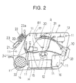
- the plastic mounting panel P is additionally provided with various functional parts and devices including at least an interior door handle 30, a handle linking cables 31, a motor R1 of the window regulator R and a front speaker 32 which are at the inner side of the plastic mounting panel P as viewed from the passenger compartment, and a guide rail R2, a drum pulley R3 and a cable R4 forming parts of the window regulator R and a door lock/unlock mechanism provided in a form of door latch unit 33 (schematically depicted in Figure 2) which are at the outer side of the plastic mounting panel P as viewed from the passenger compartment
- These functional parts and devices are attached to the plastic mounting panel P before the plastic mounting panel P is installed to the door panel sub-assembly D.
- the interior door handle 30 is installed to an upper portion of the inner side of the plastic mounting panel P as viewed from the passenger compartment.
- the handle cable 31 extends from the interior door handle 30 and the door latch unit 33.
- the motor R1 is installed to the center portion of the plastic mounting panel P.
- the front speaker 32 which forms a part of an audio system, is mounted to the speaker mount 14.
- the guide rail R2, the drum pulley R3 and the cable R4 are mounted to the center portion of the plastic mounting panel P.
- the door latch unit 33 which is engaged by a body striker (not shown), is mounted to a rear portion of the plastic mounting panel P.
- the plastic mounting panel P is additionally provided with harnesses H for supplying electric power to various electric constituent parts.
- the harnesses extend passing through a center hole 34, front half portions thereof extending on the outer side of the plastic mounting panel P as depicted by a solid line in Figure 3 and rear half portions thereof extending on the inner side of the plastic mounting panel P as depicted by solid line in Figure 2.
- the trim unit T is installed to the door panel sub-assembly D after the plastic mounting panel P is installed so as to form a side wall of the passenger compartment
- the trim unit T is formed and provided with various parts and devices including a switch unit 40 having a plurality of switches for actuating at least a power-driven window regulator and a power-driven door latch mechanism, an assist grip 41 and an arm rest 42 extending behind the switch unit 40.
- a speaker cover 43 and a pocket wall 44 are formed as appendant parts to the trim unit T.
- the speaker cover 43 is fitted on the speaker mount 14 so as to cover the front speaker 32.
- the pocket wall 44 closes one side of the pocket 15 facing the passenger compartment.
- the window glass W is installed to the door panel sub-assembly D after the plastic mounting panel P is installed. Specifically, the window glass W is inserted into the door panel sub-assembly D, i.e., between the inner door panel D1 and the outer door panel D2, from the side of the window sash D3, and then, installed to the window regulator R on the plastic mounting panel P.
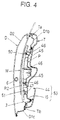
- Figure 4 shows a completed vehicle door in longitudinal-section along a vertical center line thereof.
- the guide rail R2 of the window regulator R installed to the plastic mounting panel P such as to extend in a direction of height of the vehicle.
- the window glass W is located on the outer side of the guide rail R2 so as to be guided by the guide rail R2.
- the impact bar 6 is disposed on the outer side of the window glass W such as to extend in the lengthwise direction.
- the waterproof sealing strips 19 are firmly caught between the plastic mounting panel P and the inner door panel D1, specifically the upper mounting panel Portion D1b and a lower mounting panel Portion D1c below the aperture 3 of the inner door panel D1, respectively, so as to block the aperture 3.
- the guide rail R2 is supported from the outer side thereof by the a fixing rib 45, a fixing boss 46 and an engaging boss 47 fixedly attached to or formed as a part integral with the plastic mounting panel P and is installed to the plastic mounting panel P through a fixing bolt 50 at an upper extreme end and a L-shaped tongue 51 at a lower extreme end thereof
- the trim unit T is inserted at its upper end Ta between the upper mounting panel Portion D1b of the inner door panel D1 and the window glass W and is fixed at its lower end Tb to the lower mounting panel Portion D1c of the inner door panel D1 so as thereby to be installed to the door panel sub-assembly D and to cover the plastic mounting panel P
- the pocket wall 44 is formed as a part integral with the trim unit T and forms an inner side wall of the pocket 15 when the trim unit T is installed to the door panel sub-assembly D so as thereby to complete a box-shaped pocket 53 for small articles.
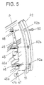
- Figures 6 and 7 show a rear lower part of the completed vehicle door in longitudinal-section.
- the inner side crash pad 16 which is formed as a part integral with the plastic mounting panel P for absorbing energy of a lateral impact against the plastic mounting panel P, projects in a direction from the exterior to the interior of the vehicle such that it extends at least toward the window glass W from the main section of the plastic mounting panel P on the side of the outer door panel D2 and toward the trim unit T on the side of the passenger compartment.
- the inner side crash pad 16 has an impact absorbing lattice structure comprising a plurality of lengthwise and breadthwise ribs 60 arranged so as to form cells open at their outer ends.
- the inner side crash pad 16 is formed in a position corresponding to the waist of a passenger sitting on a seat (not shown). This inner side crash pad 16 cooperates with an outer side crash pad 61 attached to the outer door panel D2 so as to receive energy of a lateral impact from the outer door panel D2 through the outer side crash pad 61 upon an occurrence of a side crash.
- the side crash pad 16 receives energy of a lateral impact due to a side crash, it transmits a lateral deformation of the vehicle door to the waist of the passenger, so as thereby to force the waist of the passenger away from the vehicle door. This protects the passenger from receiving a blow from the vehicle door.
- the plastic mounting panel P may be additionally provided with a fragile structure 9 comprising grooves 8 formed along a root of the inner side crash pad 16.
- a fragile structure 9 comprising grooves 8 formed along a root of the inner side crash pad 16.
- Figure 9 shows a variant of the side crash panel P which is provided with a separate side crash pad 1.
- the side crash pad 16 is prepared separately from the plastic mounting panel P and secured to the plastic mounting panel P.
- the plastic mounting panel P is formed with an aperture and the side crash pad 16 has a peripheral flange 16a.
- the side crash pad 16 is inserted and fitted in the aperture of the plastic mounting panel P by securing the peripheral flange 16a to the plastic mounting panel P by fasteners 10.
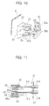
- FIG 10 is the interior door handle 30 which is exploded for the purpose of explaining a step of installing the interior door handle 30 to the plastic mounting panel P
- the interior door handle 30 is directly secured to a base block 62 formed as a part integral with the plastic mounting panel P without employing separately provided parts.
- the interior door handle 30 comprises a door lock knob 30a and a door release or unlock knob 30b. These knobs 30a and 30b are put between upper and lower brackets 63 and 64 extending from the base block 62 of the plastic mounting panel P as depicted by a double-dotted line so as to turn about a vertical axis in opposite directions.
- the door lock knob 30a has a coupling arm 65 as a part integral therewith and formed with a coupling hole 65a in which a bent end 31c of a cable rod 31a of the handle linking cable 31 is fitted.
- the door unlock knob 30b has a coupling arm 66 as a part integral therewith and formed with a coupling hole 66a in which a bent end 31d of a cable rod 31b of the handle linking cable 31 is fitted.
- the base block 62 is formed with an intermediate partition 67 extending in parallel to and between the upper and lower brackets 63 and 64.
- the handle linking cable 31 is coupled to the interior door handle 30 installed to the base block 62 of the plastic mounting panel P.
- the handle linking cable 31 comprises the cable rods 31a and 31b and cable rod guide and protect ion sheaths 31A and 31B.
- the cable rod 31a at its extreme end 31c is bent at approximately a right angle and fitted in the coupling hole 65a of the coupling arm 65.
- the cable rod 31b at its extreme end 31d is bent at approximately a right angle and fitted in the coupling hole 66ab of the coupling arm 66.
- the extreme bent ends 31c and 31d of the respective cable rods 31a and 31b are fitted in the coupling holes 65a and 66a of the coupling arms 65 and 66, respectively, first.
- the interior door handle is put and pivotally mounted between the upper bracket 63 and the lower bracket 64 so as to locate the coupling arm 65 of the door lock knob 30a between the upper bracket 63 and the intermediate partition 67 and the coupling arm 66 of the door unlock knob 30b between the intermediate partition 67 and the lower bracket 64.
- the handle linking cable coupling structure makes the upper bracket 63 function as a stopper for preventing the cable rod 31a from slipping off from the coupling arm 65 of the door lock knob 30a.
- the handle linking cable coupling structure makes the intermediate partition 67 function as a stopper for preventing the cable rod 31b from slipping off from the coupling arm 66 of the coupling arm 66 of the door unlock knob 30b.
- the cable rod guide and protection sheaths 31A and 31B are fixedly supported by a bracket 67 of the plastic mounting panel P.
- the handle linking cable coupling structure thus coupling the cable rod 31 to the interior door handle 30 provides reliable power transmission from the door lock knob 30a and the door unlock knob 30b to the door latch unit 33 for locking and unlocking the vehicle door, respectively.
- FIG 12 shows a door latch unit cover 70 by which the door latch unit 33 is covered and protected.
- the door latch unit cover 70 which is made of a plastic as one piece and has an outer shape in approximately conformity with an outer shape of the door latch unit 33, is fixed to the plastic mounting panel P through fixing brackets 71 and 72 formed as parts integral with the plastic mounting panel P
- the door latch unit cover 70 comprises four sections made up as one piece. Specifically, a cover section 73 is located at one of opposite sides of the door latch unit cover 70 to cover a cable rod of a handle linking cable 80 linking the exterior door handle 7 and a cable rod of a cylinder linking cable 81 linking a key cylinder (not shown).
- a cover section 74 is located at another side of the door latch unit cover 70 to cover a cable rod 31a of the handle linking cable 31 linking the door lock knob 30a.
- a cover section 75 is located above the cover section 74 to cover a cable rod 31b of the handle linking cable 31 linking the door unlock knob 30b.
- a cover section 76 is located at lower end of the door latch unit cover 70 to cover a motor (not shown) of the power-driven door latch unit 33.
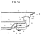
- FIG 13 shows the door latch unit 33 and its associated parts covered by the door latch unit cover 70 in cross-section.
- the door latch unit 33 is secured by fasteners 82 to the plastic mounting panel P from the outer side on which the window glass W and the outer door panel D2 are located.
- the door latch unit cover 70 protects the door latch unit 33 from an access from the outside of the vehicle with an intention to run away with the vehicle.
- the handle linking cable 31 (see Figures 1 and 2) extending from the interior door handle 30 along the plastic mounting panel P passes through an hole formed as cable guide means in rear part of the plastic mounting panel P so as to extend to the door latch unit 33 passing through the cable guide hole 83 of the plastic mounting panel P.
- the cable guide hole 83 of the plastic mounting panel P is covered by the door latch unit cover 70.
- the handle linking cable 31 is prevented from an access with an intention to run away with the vehicle.
- the handle linking cable 31 linking the door latch unit 33 extends from near the aperture 3 of the inner door panel D1 crossing the plastic mounting panel P through the cable guide hole 83 such that the handle linking cable 31 partly lies on the plastic mounting panel P on the side of the outer door panel D2 and covered by the door latch unit cover 70 together with the door latch unit 33 and partly lies on the plastic mounting plate P on the side of the passenger compartment
- the door latch unit cover 70 is prepared separately from the plastic mounting plate P and secured to the plastic mounting panel P in the above embodiment shown in Figure 13, it may be formed as a part integral with the plastic mounting plate P as one piece as shown in Figure 14.
- a generally L-shaped reinforcement 90 is welded, or otherwise secured, to the inner door panel D1 at a location where the door latch unit 33 is mounted through a fixed bolt at the rear end of the inner door panel D1 in order to provide reliable fixing stiffness of the door latch unit 33 to the inner door panel D1.
- the L-shaped reinforcement 90 which is made of a steel plate, is formed with a generally rectangular center opening 91 through which the body striker passes across when locking the vehicle door and four bolt holes 92 around the rectangular opening 91 through which bolts are inserted and fastened to the inner door panel D1 in order to fix the door latch unit 33 to the inner door panel D1.
- the L-shaped reinforcement 90 at its lower end is additionally formed with a bottom rack 93 bent on the side of the door latch unit 33.
- the door latch unit 33 itself is comparatively heavy, it is previously supported on the bottom rack 93 of the L-shaped reinforcement 90, so that the work of installing the plastic mounting panel P to the door panel sub-assembly D is made easy, as a result of which, a man-hour in assembling the front door is considerably reduced.
- Figure 17 shows the window glass guide rail 18 of the plastic mounting panel P in cross-section. While a window glass guide rail is conventionally provided separately from the inner door panel D1, however, in the vehicle door of the present invention, the window glass guide rail 18 is configured as a part integral with the plastic mounting panel P. This integrated configuration allows the window glass guide rail 18 to be easily completed by simply fitting a packing strip 18P in a groove 18a of the guide rail 18.
- Figure 18 shows the front speaker 32 attached to the speaker mount 14 of the plastic mounting panel P in cross-section.
- the speaker mount 14 projects toward the passenger compartment.
- the front speaker 32 is fitted in an opening reinforced by a ring 100 of the speaker mount 14 and is firmly secured by, for example, fixing bolts (not shown) to the speaker mount 14.
- the speaker 32 at its back is provided with a coupler 102 to which a lead wire 101 extending the harness H is connected so as to receive audio signals.
- the plastic mounting panel P is formed with a splash guard 103 extending behind and above the front speaker 32 so as to prevent electric parts associated with the front speaker 32 from, for example, raindrops.
- FIGs 19 and 20 show anchor structures of the plastic mounting panel P for anchoring the harness H and the handle linking cable 31.
- the plastic mounting panel P is formed with a harness anchor 110 as a part integral therewith for anchoring the harness H.
- the harness anchor 110 comprises a pair of L-shaped anchor lugs 110a and 110b arranged oppositely in vertical direction.
- the harness H is positioned substantially vertically and put between the L-shaped anchor lugs 110a and 110b as shown by a double-dotted line in Figure 19.
- the harness H at opposite parts is bent in opposite directions as shown by arrows so as to bring the opposite parts into engagement with the L-shaped anchor lugs 110a and 110b, respectively.
- the plastic mounting panel P is formed with a cable anchor 111 as a part integral therewith for anchoring the handle linking cable 31.
- the cable anchor 111 comprises a generally J-shaped anchor lug 111a.
- the handle linking cable 31 is inserted between the plastic mounting panel P and the J-shaped anchor lug 111a from above and seat it on the bottom of the J-shaped anchor lug 111a.
- the anchor structure comprising the harness anchor 110 and the cable anchor 111 (see Figures 19 and 20) formed as parts integral with the plastic mounting panel P eliminates any necessity to use anchor clips which have been conventionally prepared separately from the plastic mounting panel P Therefore, this anchor structure makes wiring work quite simple and easy.
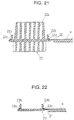
- Figures 21 and 22 show the access opening covers 22 and 23 before being separated from the plastic mounting panel P, respectively.
- the plastic mounting panel P is prepared as one piece having the access opening covers 22 and 23.
- the plastic plate P is installed to the door panel sub-assembly D with the access opening covers 22 and 23 left joined to the plastic mounting panel P.
- the access opening cover 22 is separated from the plastic mounting panel P by breaking away the joints 22a and attached to the plastic mounting panel P in position to cover up the access opening 13 which provides an access to the exterior door handle 7 for connecting the handle linking cable 31 to the interior door handle 7.
- the access opening cover 23 is separated from the plastic mounting panel P by breaking away the joints 23a and attached to the plastic mounting panel P in position to cover up the access opening 12 which provides an access to the inside of the door panel sub-assembly D for installing the window glass W to the window regulator R.
- the access opening cover 22 is formed as an appendant part joined to the plastic mounting panel P by breakable joints 20.
- the access cover 22 has an impact absorbing lattice structure comprising a plurality of ribs 22a extending in opposite directions and arranged in a lattice pattern.
- the access opening cover 22 is formed with a hook 22b extending toward the inner door panel D1 in conformity with the access opening 13 so as to surround the shock absorbing lattice structure.
- a rubber packing ring 22c is seated in an annular recess formed around the shock absorbing lattice structure before or after having separated the access opening cover 22 from the plastic mounting panel P and before attaching it to the plastic mounting panel P to cover up the access opening 13.
- the access opening cover 23 is formed as an appendant part joined to the plastic mounting panel P by breakable joints 21.
- the access cover 23 is formed with a hook 23b extending toward the inner door panel D1 in conformity with the access opening 12.
- a rubber packing ring 23c is seated in an annular recess formed around the hook 23b before or after having separated the access opening cover 23 from the plastic mounting panel P and before attaching it to the plastic mounting panel P to cover up the access opening 12.
- Figures 23 and 24 show the access covers 22 and 23 are attached in position to cover up the access openings 13 and 12, respectively.
- the access opening cover 22 is forced toward the plastic mounting panel P so as to bend and fit the hook 22b into the access opening 13 from the side of the passenger compartment as indicated by arrows A.
- the hook 22a passes across the periphery 13a of the access opening 13
- the hook 22a bends back and engages with the periphery 13a of the access opening 13. In this manner, the access opening cover 22 is easily attached in position to the plastic mounting panel P and is prevented from coming off from the access opening 13.
- the access opening cover 23 is forced toward the plastic mounting panel P so as to bend and fit the hook 23b into the access opening 12 from the side of the passenger compartment as indicated by arrows A
- the hook 23a passes across the periphery 12a of the access opening 12
- the hook 23a bends back and engages with the periphery la of the access opening 12, so that the access opening cover 23 is easily attached in position to the plastic mounting panel P and is prevented from coming off from the access opening 12.
- the vehicle door having a plastic mounting panel P to which functional devices and associated parts are mounted and which is installed to an inner door panel D1 so as to close up an aperture 3 of the inner door panel P comprises the door latch unit 33 as a door lock/unlock mechanism mounted to the inner door panel on the far side from the passenger compartment and the handle linking cable 31 as a linking member connected to the door latch unit 33 which passes through a cable guide hole 83 from near the aperture 3 of the inner door panel and extends along the plastic mounting panel partly on the far side from the passenger compartment and partly on the near side to the passenger compartment
- the handle linking cable 31 is arranged outside the internal space between the inner door panel D1 and the outer door handle D2, so as to reliably prevent the door latch unit 33 and the handle linking cable 31 from an access from the outside of the vehicle with a foul intention to run away with the vehicle.
- the vehicle door is provided with the door latch unit cover 70 which covers the door latch unit 33 and a part of the handle linking cable 31 extending along the plastic mounting panel on the far side from the passenger compartment, so as to reliably prevent the door latch unit 33 and the handle linking cable 31 from an access from the outside of the vehicle with a foul intention to run away with the vehicle.
- the door latch unit cover 70 is fixedly secured in position to the plastic mounting panel P in advance of mounting the door latch unit 33 and the handle linking member to the plastic mounting panel P. Otherwise, the door latch unit cover 70 is formed in position as a part integral with the plastic mounting panel.
- This integral structure enables to install the plastic mounting panel P with the door latch unit 33 and the handle linking cable 31 mounted thereto and the door latch unit cover 70 to the inner door panel D1 all at once. This provides an effect of simplifying assembling work of the vehicle door work and is of great advantage to decreasing the number of door parts to be assembled.
- the vehicle door is assembled by the process of mounting the latch unit 33 as a door lock/unlock member, the handle linking cable 31 as a linking member and the door latch unit cover 70 as a cover member to the plastic mounting panel P as a sub-assembly in advance such that the handle linking cable 31 passes through the cable guide hole 83 formed in the plastic mounting panel P from near the aperture 3 of the inner door panel P and extends along the plastic mounting panel P partly on the far side from the passenger compartment and partly on the near side to the passenger compartment.
- the process of assembling the vehicle door improves suitability of the vehicle door for assembling work.
Landscapes
- Engineering & Computer Science (AREA)
- Mechanical Engineering (AREA)
- Lock And Its Accessories (AREA)
- Automobile Manufacture Line, Endless Track Vehicle, Trailer (AREA)
Abstract
Description
- The present invention relates to a vehicle door comprising an outer door panel, an inner door panel formed with an aperture and a plastic mounting panel to which functional devices of the vehicle door and door parts are mounted and which is installed to the inner door panel to cover up the aperture of the inner door panel with an intention to provide a lightweight vehicle door which needs a decreased number of parts and is easy to assemble, and a process of assembling the vehicle door.
- Typically, vehicle doors are made up of a door panel assembly comprising a steel inner door panel and a steel outer door panel to which various functional parts and devices of door, such as a window regulator and a door lock mechanism, are directly installed. In such a vehicle door, because it is necessary to install various functional devices and associated parts in a space formed between the outer and inner door panels, the vehicle door is hard to be light in weight in addition to poor suitability of the plastic mounting panel for assembling work and a necessity of a large number of parts.
- In an attempt to solve the aforementioned drawbacks, there has been proposed a vehicle door which comprises an outer door panel made of a steel sheet, an inner door panel made up of a metal main panel and a plastic auxiliary panel formed as one piece. The outer door panel has an outer door wall formed as a part integral with an inner flame defining a large aperture in which the inner door panel is fitted. Various functional devices and associated parts of door are assembled to the inner door panel before fitting the inner door panel to the outer door panel. One of such vehicle doors is known from, for example, Japanese Unexamined Patent Publication No.9-156374.
- In the case where the plastic auxiliary panel is separately prepared, the inner door panel can be unrestrictedly provided with various intricate shapes. As a result, since various fitting members such as clips are unnecessary to assembling the functional parts and devices of door and, in addition, the functional parts and devices of door are allowed to be disposed at various locations, a significant effect is produced in terms of increasing the degree of freedom for laying out internal constituent parts in the inside of the vehicle door. On the other hand, since a door lock operating member such as a cable linking a door lock/unlock mechanism is usually disposed in the space of the vehicle door formed between the outer door panel and the inner door panels, the vehicle door is possibly unlocked by dishonestly or intentionally operating the door lock operating member through a gap in the window, more specifically, between an upper edge of the outer door panel and a window glass. This places the vehicle under unreliable prevention from robberies.
- It is therefore an object of the present invention to provide a vehicle door which has improved antitheft door structure.
- It is another object of the present invention to provide a vehicle door in which a linking member linking a door handle with a door lock/unlock mechanism is arranged such as to passe through a linking member guide hole of a plastic mounting panel from near an aperture of an inner door panel and then extend along the plastic mounting panel on a near side to the passenger compartment.
- It is another object of the present invention to provide a vehicle door having reliable antitheft door structure in which a cover member covers a door lock/unlock mechanism and a linking member linking a door handle with the door lock/unlock mechanism which extends along a plastic mounting panel partly on a far side from a passenger compartment.
- It is another object of the present invention to provide a vehicle door having a plastic mounting panel with a cover secured thereto for covering a door lock/unlock mechanism and a linking member linking a door handle with the door lock/unlock mechanism which extends along a plastic mounting panel partly on a far side from a passenger compartment which provides suitability of the cover for assembling work.
- It is still another object of the present invention to provide a vehicle door having a plastic mounting panel with a cover formed as a part integral therewith which reduces the number of parts of the vehicle door and provides improved suitability of the vehicle door for assembling work.
- It is a further object of the present invention to provide a process of assembling a vehicle door comprising an outer door panel disposed on a far side from a passenger compartment of a vehicle, an inner door panel formed with an aperture and disposed on a near side to the passenger compartment and a plastic mounting panel, which includes a step of mounting a door lock/unlock mechanism and a linking member through which the door lock/unlock mechanism is operated to lock and unlock the vehicle door to the plastic mounting panel and then covering them by a cover member and a step of installing the plastic mounting panel to the inner door panel so as to close up the aperture of the inner door panel.
- The aforesaid objects of the present invention are achieved by a vehicle door comprising an outer door panel disposed on a far side from a passenger compartment of a vehicle, an inner door panel formed with an aperture and disposed on a near side to the passenger compartment, and a plastic mounting panel to which functional devices of the vehicle door and door parts are mounted and which is installed to the inner door panel to cover up the aperture of the inner door panel, which comprises a door lock/unlock mechanism mounted to the inner door panel on the far side from the passenger compartment and a linking member connected to the door lock/unlock mechanism through which the door lock/unlock mechanism is operated to lock and unlock the vehicle door, the linking member passing through a linking member guide hole formed in the plastic mounting panel from near the aperture of the inner door panel and extending along the plastic mounting panel partly on the far side from the passenger compartment and partly on the near side to the passenger compartment. The vehicle door thus comprised has the linking member disposed outside a space between the inner door panel and the outer door panel, so as to provide the vehicle with an improved antitheft effect.
- The vehicle door is preferably provided with a cover member which covers the door lock/unlock mechanism and a part of the linking member extending along the plastic mounting panel on the far side from the passenger compartment The cover member reliably prevents the door lock/unlock mechanism and/or the linking member from an access from the outside of the vehicle with a foul intention to run away with the vehicle.
- The cover member is fixedly secured to the plastic mounting panel previously mounting the door lock/unlock mechanism and/or the linking member to the plastic mounting panel P. Otherwise, the cover member may be formed in position as a part integral with the plastic mounting panel. The vehicle door may further comprises an anchor member operative to anchor the linking member which is formed as a part integral with the plastic mounting panel. Further, the vehicle door may comprises a bracket member operative to hold a door handle connected to the linking member which is formed as a part integral with the plastic mounting panel. This integral structure enables to install the plastic mounting panel with the door lock/unlock mechanism and the linking member to the plastic mounting panel P mounted thereto and the cover member to the inner door panel all at once with an effect of simplifying assembling work and is of great advantage to decreasing the number of door parts to be assembled.
- The vehicle door which comprises an outer door panel disposed on a far side from a passenger compartment of the vehicle, an inner door panel formed with an aperture and disposed on a near side to the passenger compartment, and a plastic mounting panel to which functional devices of the vehicle door and door parts are mounted and which is installed to the inner door panel to close up the aperture of the inner door panel is assembled by a process comprising the steps of attaching a door lock/unlock mechanism, a linking member through and a cover member to the plastic mounting panel such that the cover member covers the door lock/unlock mechanism and the linking member from a far side from a passenger compartment of the vehicle and installing the plastic mounting panel with the door lock/unlock mechanism and the linking member covered by the cover member to the inner door panel.
- According to the process of assembling the vehicle door, the door lock/unlock mechanism, the linking member and the cover member are previously attached in position to the plastic mounting panel as a sub-assembly and thereafter the sub-assembly is installed to the inner door panel. This process improves suitability of the vehicle door for assembling work.
- The above and other objects and features of the present invention will be clearly understood from the following description with respect to the preferred embodiments thereof when considered in conjunction with the accompanying drawings, in which:
- Figure 1 is an exploded view of a vehicle door in accordance with a preferred embodiment of the present invention;
- Figure 2 is a front view of a plastic panel as viewed from a passenger compartment;
- Figure 3 is a rear view of the plastic panel as viewed from the outside of the passenger compartment;
- Figure 4 is a longitudinal-sectional view of a central part of a completed vehicle door,
- Figure 5 is an exploded view of a window glass regulator rail of a window regulator;
- Figure 6 is a longitudinal-sectional view of a rear lower part of the door panel
- Figure 7 is a perspective view of a crash pad;
- Figure 8 is a sectional view of another crash pad;
- Figure 9 is a sectional view of still another crash pad;
- Figure 10 is an exploded view of a structure for installing an interior door handle to the plastic mounting panel;
- Figure 11 is a cross-sectional view showing a linkage structure between an interior door handle and handle linking cable;
- Figure 12 is a perspective view of a door latch unit cover;
- Figure 13 is a cross-sectional view of a structure surrounding the door latch unit;
- Figure 14 is a cross-sectional view of another structure surrounding the door latch unit;
- Figure 15 is a perspective view of a reinforcement plate;
- Figure 16 is an explanatory view showing a steps of installing the plastic mounting panel to the inner door panel;
- Figure 17 is a cross-sectional view of window glass guide;
- Figure 18 is a cross-sectional view showing a speaker mounting structure;
- Figure 19 is a perspective view showing a harness fitting structure;
- Figure 20 is a perspective view showing a cable fitting structure;
- Figure 21 is a cross-sectional view of the plastic panel with a cover for an exterior door handle access opening left joined;
- Figure 22 is a cross-sectional view of the plastic panel with a cover for a window glass access opening left joined;
- Figure 23 is a cross-sectional view of the cover fitted in the exterior door handle access opening; and
- Figure 24 is a cross-sectional view of the cover fitted in the window glass access opening.
-
- Although the following description is directed to a front door of a vehicle by way of example, the present invention is applicable to a rear door and a back door with the same effects.
- Referring to the drawings in detail, and, in particular, to Figures 1 to 3 showing a front door of a vehicle (which will be referred to as a vehicle door for simplicity) in accordance with a preferred embodiment of the present invention, the vehicle door is made up of a door panel sub-assembly D comprising a steel inner door panel D1 disposed on a side far from a passenger compartment of the vehicle, a steel outer door panel D2 disposed on a side neat to the passenger compartment, a steel window sash D3, a plastic mounting panel P, and a trim unit T which forms a side wall of a passenger compartment. The window sash D3, which is shaped such as to have a front part inclined rearward as viewed from the front of the vehicle, receives an window glass W therein. The door panel sub-assembly D at its front end is provided upper and
lower hinges rectangular aperture 3 formed below a belt line and has a front top comer D1a uncut An upper mounting panel Portion D1b above the belt line and integral with the uncut part D1a provides the inner door panel D1 with structural rigidity at least necessary for an inner panel. The inner door panel D1 is formed with a plurality ofholes 4 arranged around theaperture 3 for fastening clips and set screws (not shown) for attaching the plastic mounting panel P and the trim unit T to the door panel sub-assembly D. - The door panel sub-assembly D is equipped with an
impact bar 6 extending in a lengthwise direction of the vehicle between the inner door panel D1 and the outer door panel D2 in order to provides the door panel sub-assembly D with increased rigidity against side impact thereon. The outer door panel D2 is provided with anexterior door handle 7 at its rear top comer thereof The plastic mounting panel P has an overall shape in almost conformity to theaperture 3 of the inner door panel D1. The plastic mounting panel P is formed with a plurality ofholes 11 arranged along the peripheral margin so as to correspond in position to theholes 4 of the inner door panel D1. Further, the plastic mounting panel P at its center portion is formed with anopening 12 for an access to the inside of the door panel sub-assembly D for installing the window glass W to a window regulator R. The plastic mounting panel P at its rear top comer is formed with anopening 13 for an access to the inside of the door panel sub-assembly D for connecting a wire cable and its associated parts to theexterior door handle 7. The plastic mounting panel P is further formed with aspeaker mount 14, apocket 15 and anside crash pad 16 operative to absorb energy of an impact, all of which are arranged in the lengthwise direction at a lower portion of the plastic plate P and project toward the passenger compartment, and abracket 17 positioned at a center thereof. The trim unit T is fixed to the plastic mounting panel P, and hence the door panel sub-assembly D, through thebracket 17. - As shown in detail in Figure 3 showing an appearance of the plastic mounting panel P as viewed from the outside of the passenger compartment, the plastic mounting panel P is formed and provided with various constituent parts including at least a window
glass guide rail 18, a sealingmember 19, and access opening covers 22 and 23. Specifically, the windowglass guide rail 18 is attached to a front portion of the plastic mounting panel P so as to guide up and down movement of the window glass W. The sealingmember 19, which is made of, for example, waterproof rubber strip, attached to the plastic mounting panel P so as to extend along the periphery except an upper side of the plastic mounting panel P. Theaccess opening cover 22 is formed as an appendant part to the plastic mounting panel P at a front upper cutaway comer so as to be easily separated from the plastic mounting panel P by braking away joints 20 after it has been attached to the plastic mounting panel P to cover up theaccess opening 13. Similarly, theaccess opening cover 23 is formed as an appendant part to the plastic mounting panel P at the front upper cutaway comer so as to be easily separated from the plastic mounting panel P by breaking awayjoints 21 after it has been attached to the plastic mounting panel P to cover up theaccess opening 12. Theaccess opening cover 22 is formed with a shock absorbing latticestructure comprising ribs 22a and installed to the plastic mounting panel P such that, when the plastic mounting panel P is installed to the door panel sub-assembly D, theaccess opening cover 22 absorbs impact from theexterior door handle 7. - As shown in Figures 1 to 3, the plastic mounting panel P is additionally provided with various functional parts and devices including at least an
interior door handle 30, ahandle linking cables 31, a motor R1 of the window regulator R and afront speaker 32 which are at the inner side of the plastic mounting panel P as viewed from the passenger compartment, and a guide rail R2, a drum pulley R3 and a cable R4 forming parts of the window regulator R and a door lock/unlock mechanism provided in a form of door latch unit 33 (schematically depicted in Figure 2) which are at the outer side of the plastic mounting panel P as viewed from the passenger compartment These functional parts and devices are attached to the plastic mounting panel P before the plastic mounting panel P is installed to the door panel sub-assembly D. Specifically, theinterior door handle 30 is installed to an upper portion of the inner side of the plastic mounting panel P as viewed from the passenger compartment. Thehandle cable 31 extends from theinterior door handle 30 and thedoor latch unit 33. The motor R1 is installed to the center portion of the plastic mounting panel P. Thefront speaker 32, which forms a part of an audio system, is mounted to thespeaker mount 14. The guide rail R2, the drum pulley R3 and the cable R4 are mounted to the center portion of the plastic mounting panel P. Thedoor latch unit 33, which is engaged by a body striker (not shown), is mounted to a rear portion of the plastic mounting panel P. The plastic mounting panel P is additionally provided with harnesses H for supplying electric power to various electric constituent parts. The harnesses extend passing through acenter hole 34, front half portions thereof extending on the outer side of the plastic mounting panel P as depicted by a solid line in Figure 3 and rear half portions thereof extending on the inner side of the plastic mounting panel P as depicted by solid line in Figure 2. - As seen in Figure 1, the trim unit T is installed to the door panel sub-assembly D after the plastic mounting panel P is installed so as to form a side wall of the passenger compartment The trim unit T is formed and provided with various parts and devices including a
switch unit 40 having a plurality of switches for actuating at least a power-driven window regulator and a power-driven door latch mechanism, anassist grip 41 and anarm rest 42 extending behind theswitch unit 40. In addition, aspeaker cover 43 and apocket wall 44 are formed as appendant parts to the trim unit T. Thespeaker cover 43 is fitted on thespeaker mount 14 so as to cover thefront speaker 32. Thepocket wall 44 closes one side of thepocket 15 facing the passenger compartment. - The window glass W is installed to the door panel sub-assembly D after the plastic mounting panel P is installed. Specifically, the window glass W is inserted into the door panel sub-assembly D, i.e., between the inner door panel D1 and the outer door panel D2, from the side of the window sash D3, and then, installed to the window regulator R on the plastic mounting panel P.
- Details of the respective parts and devices of the vehicle door will be described below in conjunction with Figures 4 through 24.
- Figure 4 shows a completed vehicle door in longitudinal-section along a vertical center line thereof. In an interior space of the door panel sub-assembly D formed between the inner door panel D1 and the outer door panel D2 there is disposed the guide rail R2 of the window regulator R installed to the plastic mounting panel P such as to extend in a direction of height of the vehicle. The window glass W is located on the outer side of the guide rail R2 so as to be guided by the guide rail R2. The
impact bar 6 is disposed on the outer side of the window glass W such as to extend in the lengthwise direction. In order to provide the passenger compartment with reliable watertightness, the waterproof sealing strips 19 are firmly caught between the plastic mounting panel P and the inner door panel D1, specifically the upper mounting panel Portion D1b and a lower mounting panel Portion D1c below theaperture 3 of the inner door panel D1, respectively, so as to block theaperture 3. The guide rail R2 is supported from the outer side thereof by the a fixingrib 45, a fixingboss 46 and an engagingboss 47 fixedly attached to or formed as a part integral with the plastic mounting panel P and is installed to the plastic mounting panel P through a fixingbolt 50 at an upper extreme end and a L-shapedtongue 51 at a lower extreme end thereof The trim unit T is inserted at its upper end Ta between the upper mounting panel Portion D1b of the inner door panel D1 and the window glass W and is fixed at its lower end Tb to the lower mounting panel Portion D1c of the inner door panel D1 so as thereby to be installed to the door panel sub-assembly D and to cover the plastic mounting panel P Thepocket wall 44 is formed as a part integral with the trim unit T and forms an inner side wall of thepocket 15 when the trim unit T is installed to the door panel sub-assembly D so as thereby to complete a box-shapedpocket 53 for small articles. - As shown in Figure 5, in the installing process of installing the guide rail R2 of the window regulator R to the plastic mounting panel P, after temporarily keeping the guide rail R2 in position relative to the plastic mounting panel P first by inserting the L-shaped
tongue 51 of the guide rail R2 into aslot 47a of theengagement boss 47, positioning and engagingpins 46a extending from the fixingbosses 46 are engaged within holes R2a formed in the guide rail R2, respectively. Finally, the fixingbolt 50 is passed through one of the holes R2b and fastened into one of the fixingbosses 46 so as thereby to firmly fix the guide rail R2 to the plastic mounting panel P. In this manner, the assembling work of the guide rail R2 is made easy. - Figures 6 and 7 show a rear lower part of the completed vehicle door in longitudinal-section. As shown, the inner
side crash pad 16, which is formed as a part integral with the plastic mounting panel P for absorbing energy of a lateral impact against the plastic mounting panel P, projects in a direction from the exterior to the interior of the vehicle such that it extends at least toward the window glass W from the main section of the plastic mounting panel P on the side of the outer door panel D2 and toward the trim unit T on the side of the passenger compartment. The innerside crash pad 16 has an impact absorbing lattice structure comprising a plurality of lengthwise andbreadthwise ribs 60 arranged so as to form cells open at their outer ends. The innerside crash pad 16 is formed in a position corresponding to the waist of a passenger sitting on a seat (not shown). This innerside crash pad 16 cooperates with an outerside crash pad 61 attached to the outer door panel D2 so as to receive energy of a lateral impact from the outer door panel D2 through the outerside crash pad 61 upon an occurrence of a side crash. When theside crash pad 16 receives energy of a lateral impact due to a side crash, it transmits a lateral deformation of the vehicle door to the waist of the passenger, so as thereby to force the waist of the passenger away from the vehicle door. This protects the passenger from receiving a blow from the vehicle door. - As shown in Figure 8, the plastic mounting panel P may be additionally provided with a
fragile structure 9 comprisinggrooves 8 formed along a root of the innerside crash pad 16. When the innerside crash pad 16 receives energy of an impact from the outerside crash pad 61 upon an occurrence of a side crash, thefragile structure 9 breaks off along thegrooves 8, so that the innerside crash pad 16 moves quickly into the passenger compartment, forcing the waist of the passenger away from the door panel in an early stage of the side crash. Therefore, theinner side pad 16 provided with thefragile structure 9 provides the vehicle with an improved protection performance for the passenger. - Figure 9 shows a variant of the side crash panel P which is provided with a separate
side crash pad 1. As shown in Figure 9, theside crash pad 16 is prepared separately from the plastic mounting panel P and secured to the plastic mounting panel P. Specifically, the plastic mounting panel P is formed with an aperture and theside crash pad 16 has a peripheral flange 16a. Theside crash pad 16 is inserted and fitted in the aperture of the plastic mounting panel P by securing the peripheral flange 16a to the plastic mounting panel P byfasteners 10. - Figure 10 is the interior door handle 30 which is exploded for the purpose of explaining a step of installing the interior door handle 30 to the plastic mounting panel P As shown, the
interior door handle 30 is directly secured to abase block 62 formed as a part integral with the plastic mounting panel P without employing separately provided parts. Theinterior door handle 30 comprises adoor lock knob 30a and a door release or unlockknob 30b. Theseknobs lower brackets base block 62 of the plastic mounting panel P as depicted by a double-dotted line so as to turn about a vertical axis in opposite directions. Thedoor lock knob 30a has acoupling arm 65 as a part integral therewith and formed with acoupling hole 65a in which a bent end 31c of acable rod 31a of thehandle linking cable 31 is fitted. Similarly, the door unlockknob 30b has acoupling arm 66 as a part integral therewith and formed with acoupling hole 66a in which abent end 31d of acable rod 31b of thehandle linking cable 31 is fitted. Thebase block 62 is formed with anintermediate partition 67 extending in parallel to and between the upper andlower brackets - As depicted in detail in Figure 11, the
handle linking cable 31 is coupled to the interior door handle 30 installed to thebase block 62 of the plastic mounting panel P. Thehandle linking cable 31 comprises thecable rods ion sheaths cable rod 31a at its extreme end 31c is bent at approximately a right angle and fitted in thecoupling hole 65a of thecoupling arm 65. Thecable rod 31b at itsextreme end 31d is bent at approximately a right angle and fitted in the coupling hole 66ab of thecoupling arm 66. In the step of coupling thehandle linking cable 31 to theinterior door handle 31, namely thedoor lock knob 30a and the door unlockknob 30b, the extreme bent ends 31c and 31d of therespective cable rods coupling holes coupling arms upper bracket 63 and thelower bracket 64 so as to locate thecoupling arm 65 of thedoor lock knob 30a between theupper bracket 63 and theintermediate partition 67 and thecoupling arm 66 of the door unlockknob 30b between theintermediate partition 67 and thelower bracket 64. The handle linking cable coupling structure makes theupper bracket 63 function as a stopper for preventing thecable rod 31a from slipping off from thecoupling arm 65 of thedoor lock knob 30a. Similarly, the handle linking cable coupling structure makes theintermediate partition 67 function as a stopper for preventing thecable rod 31b from slipping off from thecoupling arm 66 of thecoupling arm 66 of the door unlockknob 30b. The cable rod guide andprotection sheaths bracket 67 of the plastic mounting panel P. - As described above, the handle linking cable coupling structure thus coupling the
cable rod 31 to theinterior door handle 30 provides reliable power transmission from thedoor lock knob 30a and the door unlockknob 30b to thedoor latch unit 33 for locking and unlocking the vehicle door, respectively. - Figure 12 shows a door latch unit cover 70 by which the
door latch unit 33 is covered and protected. The doorlatch unit cover 70, which is made of a plastic as one piece and has an outer shape in approximately conformity with an outer shape of thedoor latch unit 33, is fixed to the plastic mounting panel P through fixingbrackets latch unit cover 70 comprises four sections made up as one piece. Specifically, acover section 73 is located at one of opposite sides of the door latch unit cover 70 to cover a cable rod of ahandle linking cable 80 linking theexterior door handle 7 and a cable rod of acylinder linking cable 81 linking a key cylinder (not shown). Acover section 74 is located at another side of the door latch unit cover 70 to cover acable rod 31a of thehandle linking cable 31 linking thedoor lock knob 30a. Acover section 75 is located above thecover section 74 to cover acable rod 31b of thehandle linking cable 31 linking the door unlockknob 30b. Acover section 76 is located at lower end of the door latch unit cover 70 to cover a motor (not shown) of the power-drivendoor latch unit 33. - Figure 13 shows the
door latch unit 33 and its associated parts covered by the door latch unit cover 70 in cross-section. Thedoor latch unit 33 is secured byfasteners 82 to the plastic mounting panel P from the outer side on which the window glass W and the outer door panel D2 are located. The doorlatch unit cover 70 protects thedoor latch unit 33 from an access from the outside of the vehicle with an intention to run away with the vehicle. The handle linking cable 31 (see Figures 1 and 2) extending from the interior door handle 30 along the plastic mounting panel P passes through an hole formed as cable guide means in rear part of the plastic mounting panel P so as to extend to thedoor latch unit 33 passing through thecable guide hole 83 of the plastic mounting panel P. Thecable guide hole 83 of the plastic mounting panel P is covered by the doorlatch unit cover 70. Because the most part of thehandle linking cable 31 lays on the inner side of the plastic mounting panel P and because thehandle linking cable 31 is linked with thedoor latch unit 33 within the doorlatch unit cover 70, thehandle linking cable 31 is prevented from an access with an intention to run away with the vehicle. In other words, thehandle linking cable 31 linking thedoor latch unit 33 extends from near theaperture 3 of the inner door panel D1 crossing the plastic mounting panel P through thecable guide hole 83 such that thehandle linking cable 31 partly lies on the plastic mounting panel P on the side of the outer door panel D2 and covered by the door latch unit cover 70 together with thedoor latch unit 33 and partly lies on the plastic mounting plate P on the side of the passenger compartment - Although the door
latch unit cover 70 is prepared separately from the plastic mounting plate P and secured to the plastic mounting panel P in the above embodiment shown in Figure 13, it may be formed as a part integral with the plastic mounting plate P as one piece as shown in Figure 14. A generally L-shapedreinforcement 90 is welded, or otherwise secured, to the inner door panel D1 at a location where thedoor latch unit 33 is mounted through a fixed bolt at the rear end of the inner door panel D1 in order to provide reliable fixing stiffness of thedoor latch unit 33 to the inner door panel D1. - Referring to Figure 15 showing the L-shaped
reinforcement 90 in detail, the L-shapedreinforcement 90, which is made of a steel plate, is formed with a generally rectangular center opening 91 through which the body striker passes across when locking the vehicle door and fourbolt holes 92 around therectangular opening 91 through which bolts are inserted and fastened to the inner door panel D1 in order to fix thedoor latch unit 33 to the inner door panel D1. The L-shapedreinforcement 90 at its lower end is additionally formed with abottom rack 93 bent on the side of thedoor latch unit 33. While thedoor latch unit 33 itself is comparatively heavy, it is previously supported on thebottom rack 93 of the L-shapedreinforcement 90, so that the work of installing the plastic mounting panel P to the door panel sub-assembly D is made easy, as a result of which, a man-hour in assembling the front door is considerably reduced. - As shown in Figure 16, in order to install the plastic mounting panel P to the inner door panel D1, after installing the
door latch unit 33, thehandle linking cable 31 and the door latch unit cover 70 to the plastic mounting panel P beforehand, the plastic mounting panel P is attached and fixed to the inner door panel P so as to close theaperture 3 of the inner door panel D1. At this time, thedoor latch unit 33 is previously supported on thebottom rack 93 of the L-shapedreinforcement 90. This provides improvement of workability in installing the plastic mounting panel P to the door panel sub-assembly D. - Figure 17 shows the window
glass guide rail 18 of the plastic mounting panel P in cross-section. While a window glass guide rail is conventionally provided separately from the inner door panel D1, however, in the vehicle door of the present invention, the windowglass guide rail 18 is configured as a part integral with the plastic mounting panel P. This integrated configuration allows the windowglass guide rail 18 to be easily completed by simply fitting apacking strip 18P in agroove 18a of theguide rail 18. - Figure 18 shows the
front speaker 32 attached to thespeaker mount 14 of the plastic mounting panel P in cross-section. The speaker mount 14 projects toward the passenger compartment. Thefront speaker 32 is fitted in an opening reinforced by aring 100 of thespeaker mount 14 and is firmly secured by, for example, fixing bolts (not shown) to thespeaker mount 14. Thespeaker 32 at its back is provided with acoupler 102 to which alead wire 101 extending the harness H is connected so as to receive audio signals. The plastic mounting panel P is formed with asplash guard 103 extending behind and above thefront speaker 32 so as to prevent electric parts associated with thefront speaker 32 from, for example, raindrops. - Figures 19 and 20 show anchor structures of the plastic mounting panel P for anchoring the harness H and the
handle linking cable 31. As shown in Figure 19, the plastic mounting panel P is formed with aharness anchor 110 as a part integral therewith for anchoring the harness H. Theharness anchor 110 comprises a pair of L-shaped anchor lugs 110a and 110b arranged oppositely in vertical direction. In order to anchor the harness H, the harness H is positioned substantially vertically and put between the L-shaped anchor lugs 110a and 110b as shown by a double-dotted line in Figure 19. Then, the harness H at opposite parts is bent in opposite directions as shown by arrows so as to bring the opposite parts into engagement with the L-shaped anchor lugs 110a and 110b, respectively. On the other hand, as shown in Figure 20, the plastic mounting panel P is formed with acable anchor 111 as a part integral therewith for anchoring thehandle linking cable 31. Thecable anchor 111 comprises a generally J-shapedanchor lug 111a. In order to anchor thehandle linking cable 31, thehandle linking cable 31 is inserted between the plastic mounting panel P and the J-shapedanchor lug 111a from above and seat it on the bottom of the J-shapedanchor lug 111a. The anchor structure comprising theharness anchor 110 and the cable anchor 111 (see Figures 19 and 20) formed as parts integral with the plastic mounting panel P eliminates any necessity to use anchor clips which have been conventionally prepared separately from the plastic mounting panel P Therefore, this anchor structure makes wiring work quite simple and easy. - Figures 21 and 22 show the access opening covers 22 and 23 before being separated from the plastic mounting panel P, respectively. As was previously described, the plastic mounting panel P is prepared as one piece having the access opening covers 22 and 23. The plastic plate P is installed to the door panel sub-assembly D with the access opening covers 22 and 23 left joined to the plastic mounting panel P. After having attached the plastic mounting panel P to the door panel sub-assembly D, the
access opening cover 22 is separated from the plastic mounting panel P by breaking away thejoints 22a and attached to the plastic mounting panel P in position to cover up the access opening 13 which provides an access to theexterior door handle 7 for connecting thehandle linking cable 31 to theinterior door handle 7. Similarly, after attaching the plastic panel tot he door panel sub-assembly D, theaccess opening cover 23 is separated from the plastic mounting panel P by breaking away the joints 23a and attached to the plastic mounting panel P in position to cover up the access opening 12 which provides an access to the inside of the door panel sub-assembly D for installing the window glass W to the window regulator R. Specifically, as shown in Figure 21, theaccess opening cover 22 is formed as an appendant part joined to the plastic mounting panel P bybreakable joints 20. The access cover 22 has an impact absorbing lattice structure comprising a plurality ofribs 22a extending in opposite directions and arranged in a lattice pattern. Theaccess opening cover 22 is formed with ahook 22b extending toward the inner door panel D1 in conformity with the access opening 13 so as to surround the shock absorbing lattice structure. Arubber packing ring 22c is seated in an annular recess formed around the shock absorbing lattice structure before or after having separated theaccess opening cover 22 from the plastic mounting panel P and before attaching it to the plastic mounting panel P to cover up theaccess opening 13. As shown in Figure 22, theaccess opening cover 23 is formed as an appendant part joined to the plastic mounting panel P bybreakable joints 21. The access cover 23 is formed with ahook 23b extending toward the inner door panel D1 in conformity with theaccess opening 12. Arubber packing ring 23c is seated in an annular recess formed around thehook 23b before or after having separated theaccess opening cover 23 from the plastic mounting panel P and before attaching it to the plastic mounting panel P to cover up theaccess opening 12. - Figures 23 and 24 show the access covers 22 and 23 are attached in position to cover up the
access openings access opening cover 22 is forced toward the plastic mounting panel P so as to bend and fit thehook 22b into the access opening 13 from the side of the passenger compartment as indicated by arrows A. When thehook 22a passes across theperiphery 13a of the access opening 13, thehook 22a bends back and engages with theperiphery 13a of theaccess opening 13. In this manner, theaccess opening cover 22 is easily attached in position to the plastic mounting panel P and is prevented from coming off from theaccess opening 13. Similarly, as shown in Figure 24, theaccess opening cover 23 is forced toward the plastic mounting panel P so as to bend and fit thehook 23b into the access opening 12 from the side of the passenger compartment as indicated by arrows A When the hook 23a passes across theperiphery 12a of the access opening 12, the hook 23a bends back and engages with the periphery la of the access opening 12, so that theaccess opening cover 23 is easily attached in position to the plastic mounting panel P and is prevented from coming off from theaccess opening 12. - As fully described in detail above in connection with the preferred embodiment, the vehicle door having a plastic mounting panel P to which functional devices and associated parts are mounted and which is installed to an inner door panel D1 so as to close up an
aperture 3 of the inner door panel P comprises thedoor latch unit 33 as a door lock/unlock mechanism mounted to the inner door panel on the far side from the passenger compartment and thehandle linking cable 31 as a linking member connected to thedoor latch unit 33 which passes through acable guide hole 83 from near theaperture 3 of the inner door panel and extends along the plastic mounting panel partly on the far side from the passenger compartment and partly on the near side to the passenger compartment According to the vehicle door thus comprised, thehandle linking cable 31 is arranged outside the internal space between the inner door panel D1 and the outer door handle D2, so as to reliably prevent thedoor latch unit 33 and thehandle linking cable 31 from an access from the outside of the vehicle with a foul intention to run away with the vehicle. - The vehicle door is provided with the door latch unit cover 70 which covers the
door latch unit 33 and a part of thehandle linking cable 31 extending along the plastic mounting panel on the far side from the passenger compartment, so as to reliably prevent thedoor latch unit 33 and thehandle linking cable 31 from an access from the outside of the vehicle with a foul intention to run away with the vehicle. The doorlatch unit cover 70 is fixedly secured in position to the plastic mounting panel P in advance of mounting thedoor latch unit 33 and the handle linking member to the plastic mounting panel P. Otherwise, the doorlatch unit cover 70 is formed in position as a part integral with the plastic mounting panel. This integral structure enables to install the plastic mounting panel P with thedoor latch unit 33 and thehandle linking cable 31 mounted thereto and the door latch unit cover 70 to the inner door panel D1 all at once. This provides an effect of simplifying assembling work of the vehicle door work and is of great advantage to decreasing the number of door parts to be assembled. - The vehicle door is assembled by the process of mounting the
latch unit 33 as a door lock/unlock member, thehandle linking cable 31 as a linking member and the door latch unit cover 70 as a cover member to the plastic mounting panel P as a sub-assembly in advance such that thehandle linking cable 31 passes through thecable guide hole 83 formed in the plastic mounting panel P from near theaperture 3 of the inner door panel P and extends along the plastic mounting panel P partly on the far side from the passenger compartment and partly on the near side to the passenger compartment The process of assembling the vehicle door improves suitability of the vehicle door for assembling work.
Claims (7)
- A vehicle door comprising an outer door panel (D2) disposed on a far side from a passenger compartment of a vehicle, an inner door panel (D1) formed with an aperture (3) and disposed on a near side to the passenger compartment, and a plastic mounting panel (P) to which functional devices of the vehicle door and door parts are mounted and which is installed to the inner door panel (D1) to cover up the aperture (3) of the inner door panel (D1), said vehicle door comprising:a door lock/unlock mechanism (33) mounted to the plastic mounting panel (P) on said far side from the passenger compartment, said door lock/unlock mechanism (33) being operative to lock and unlock the vehicle door,a linking member (31) connected to said door lock/unlock mechanism (33) through which said door lock/unlock mechanism (33) is operated; anda linking member guide hole (83) formed in the plastic mounting panel (P);wherein said linking member (31) passes through said linking member guide hole (83) from near the aperture (3) of the inner door panel (D1) and extends along the plastic mounting panel (P) partly on said far side from the passenger compartment and partly on said near side to the passenger compartment
- A vehicle door as defined in claim 1, and further comprising a cover member (70) operative to cover said door lock/unlock mechanism (33) and said linking member (31) extending along the plastic mounting panel (P) on said far side from the passenger compartment
- A vehicle door as defined in claim 2, wherein said cover member (70) is fixedly secured to the plastic mounting panel (P).
- A vehicle door as defined in claim 2, wherein said cover member (70) is formed as a part integral with the plastic mounting panel (P).
- A vehicle door as defined in one of the preceding claims 1 to 4, and further comprising an anchor member (111) operative to anchor said linking member (31), said anchoring member (111) being formed as a part integral with the plastic mounting panel (P) at a side of the passenger compartment.
- A vehicle door as defined in one of the preceding claims 1 to 5, and further comprising a bracket member (62, 63, 64) operative to hold a door handle (30) connected to said linking member (31), said bracket member (62, 63, 64) being formed as a part integral with the plastic mounting panel (P) at a side of the passenger compartment
- A door assembling process of assembling a vehicle door for a vehicle which comprises an outer door panel (D2) disposed on a far side from a passenger compartment of the vehicle, an inner door panel (D1) formed with an aperture (3) and disposed on a near side to the passenger compartment, and a plastic mounting panel (P) to which functional devices of the vehicle door and door parts are mounted and which is installed to the inner door panel (D1) to close up the aperture (3) of the inner door panel (D1), said door assembling process comprising the steps ofmounting a door lock/unlock mechanism (33), a linking member (31) through which said door lock/unlock mechanism (33) is operated to lock and unlock the vehicle door, and a cover member (70) to the plastic mounting panel (P) such that said cover member (70) covers said door lock/unlock mechanism (33) and said linking member (31) from a far side from a passenger compartment of the vehicle; andinstalling the plastic mounting panel (P) with said door lock/unlock mechanism (33), said linking member (31) and said cover member (70) installed to the inner door pane (D1).
Applications Claiming Priority (2)
| Application Number | Priority Date | Filing Date | Title |
|---|---|---|---|
| JP2000053668 | 2000-02-29 | ||
| JP2000053668A JP3873566B2 (en) | 2000-02-29 | 2000-02-29 | Automobile door and method of assembling the autodoor |
Publications (4)
| Publication Number | Publication Date |
|---|---|
| EP1129874A2 true EP1129874A2 (en) | 2001-09-05 |
| EP1129874A3 EP1129874A3 (en) | 2003-04-02 |
| EP1129874B1 EP1129874B1 (en) | 2004-10-06 |
| EP1129874B2 EP1129874B2 (en) | 2010-04-07 |
Family
ID=18575020
Family Applications (1)
| Application Number | Title | Priority Date | Filing Date |
|---|---|---|---|
| EP20010103361 Expired - Lifetime EP1129874B2 (en) | 2000-02-29 | 2001-02-13 | Vehicle door and process of assembling the vehicle door |
Country Status (4)
| Country | Link |
|---|---|
| US (1) | US6725606B2 (en) |
| EP (1) | EP1129874B2 (en) |
| JP (1) | JP3873566B2 (en) |
| DE (1) | DE60106109T3 (en) |
Cited By (5)
| Publication number | Priority date | Publication date | Assignee | Title |
|---|---|---|---|---|
| FR2839934A1 (en) | 2002-05-22 | 2003-11-28 | Meritor Light Vehicle Sys Ltd | BASIN PUSH BUTTON AND ASSEMBLY METHOD THEREFOR |
| EP1698503A1 (en) * | 2005-03-01 | 2006-09-06 | Grupo Antolin-Ingenieria, S.A. | Structural supporting module for vehicle doors |
| EP1758748A1 (en) * | 2004-06-23 | 2007-03-07 | Intier Automotive Closures Inc. | Structural door module |
| EP1689959B2 (en) † | 2003-11-14 | 2010-11-03 | Integración De Montajes Y Plásticos, S.L. | Inside door element for a motor vehicle comprising a cover used as a break-in prevention device |
| FR3016556A1 (en) * | 2014-01-21 | 2015-07-24 | Peugeot Citroen Automobiles Sa | DEVICE FOR PREVENTING THE OPENING OF A SIDE DOOR OF A MOTOR VEHICLE IN CASES OF LATERAL SHOCK |
Families Citing this family (26)
| Publication number | Priority date | Publication date | Assignee | Title |
|---|---|---|---|---|
| JP4669177B2 (en) * | 2001-09-26 | 2011-04-13 | アイシン精機株式会社 | Automobile sliding door opening movement restriction device |
| DE10326154B4 (en) * | 2003-06-06 | 2005-09-08 | Johnson Controls Interiors Gmbh & Co. Kg | Door module for vehicle door |
| US6938944B2 (en) * | 2004-01-20 | 2005-09-06 | Foamade Industries, Inc. | Water shield with integrated 3-D mirror seal |
| US7044533B2 (en) * | 2004-02-04 | 2006-05-16 | Lear Corporation | Wrapped bolster seal |
| JP4650668B2 (en) * | 2004-09-27 | 2011-03-16 | マツダ株式会社 | Car door structure |
| EP1804696B1 (en) * | 2004-10-06 | 2010-12-08 | Covidien AG | Systems and methods for thermally profiling radiofrequency electrodes |
| US20060086049A1 (en) * | 2004-10-25 | 2006-04-27 | Freightliner Llc | Door module for vehicle door |
| DE102005017615A1 (en) * | 2005-04-15 | 2006-10-19 | Arvinmeritor Gmbh | Vehicle door assembly comprising internal sheet with attached support for sliding window components, employs hooked- or catch connections rather than screws |
| US8002462B2 (en) * | 2006-09-13 | 2011-08-23 | Covidien Ag | Portable thermally profiling phantom and method of using the same |
| JP5148870B2 (en) * | 2006-12-15 | 2013-02-20 | 三井金属アクト株式会社 | Car door structure |
| JP4978862B2 (en) * | 2008-02-19 | 2012-07-18 | 関東自動車工業株式会社 | Shock absorption structure of automobile |
| DE102010050959A1 (en) * | 2010-11-10 | 2012-05-10 | Gm Global Technology Operations Llc (N.D.Ges.D. Staates Delaware) | Mounting arrangement for mounting a trim panel |
| US9382732B2 (en) * | 2011-01-21 | 2016-07-05 | GM Global Technology Operations LLC | Door assembly with anti-theft device |
| JP5487194B2 (en) * | 2011-12-28 | 2014-05-07 | 本田技研工業株式会社 | Vehicle door |
| DE102012214836B4 (en) * | 2012-08-21 | 2016-09-01 | Brose Fahrzeugteile Gmbh & Co. Kommanditgesellschaft, Bamberg | Vehicle door with a multifunction carrier |
| JP6330610B2 (en) * | 2014-10-07 | 2018-05-30 | トヨタ自動車株式会社 | Side door structure for vehicles |
| JP6435823B2 (en) * | 2014-12-04 | 2018-12-12 | アイシン精機株式会社 | Sliding door module |
| DE102015205667B3 (en) * | 2015-03-30 | 2016-06-02 | Brose Fahrzeugteile Gmbh & Co. Kg, Hallstadt | Carrier component with special sealing channel |
| JP6501118B2 (en) | 2015-08-21 | 2019-04-17 | トヨタ紡織株式会社 | Shock absorption structure |
| US10619396B2 (en) * | 2015-09-17 | 2020-04-14 | Faraday&Future Inc. | Active pivoting window regulator system |
| JP6765351B2 (en) * | 2017-07-12 | 2020-10-07 | 本田技研工業株式会社 | Vehicle door structure |
| JP7124302B2 (en) * | 2017-11-30 | 2022-08-24 | トヨタ紡織株式会社 | vehicle door |
| KR102463200B1 (en) * | 2017-12-08 | 2022-11-04 | 현대자동차 주식회사 | Door for vehicle |
| CN113442959B (en) * | 2020-03-25 | 2023-02-03 | 中车唐山机车车辆有限公司 | Modular carriage side wall structure, carriage side wall and mounting method |
| US11525297B2 (en) * | 2020-06-30 | 2022-12-13 | Brose Fahrzeugteile Se & Co. Kommanditgesellschaft, Bamberg | Integrated window regulator and method of making the same |
| CN113561739B (en) * | 2021-06-22 | 2023-02-14 | 徐州徐工挖掘机械有限公司 | Door device and excavator |
Citations (1)
| Publication number | Priority date | Publication date | Assignee | Title |
|---|---|---|---|---|
| JPH09156374A (en) | 1995-12-08 | 1997-06-17 | Yazaki Corp | Automotive door |
Family Cites Families (17)
| Publication number | Priority date | Publication date | Assignee | Title |
|---|---|---|---|---|
| US4603894A (en) * | 1984-03-22 | 1986-08-05 | General Motors Corporation | Lock and handle module for vehicle door |
| FR2648762B1 (en) * | 1989-06-27 | 1991-10-18 | Rockwell Cim | INTERIOR TRIM PANEL OF A VEHICLE DOOR, CORRESPONDING DOOR, AND METHOD OF MOUNTING THE DOOR |
| US5251403A (en) * | 1992-03-16 | 1993-10-12 | General Motors Corporation | Tubular plastic mounting panel for door hardware |
| US5535553A (en) * | 1994-11-16 | 1996-07-16 | General Motors Corporation | Superplug vehicle door module |
| DE4444406A1 (en) * | 1994-12-14 | 1996-06-20 | Brose Fahrzeugteile | Motor vehicle door |
| DE19511105C1 (en) * | 1995-03-25 | 1996-11-21 | Brose Fahrzeugteile | Double-skin vehicle door with a double-strand cable window lifter pre-assembled on a carrier plate |
| GB2299309B (en) * | 1995-03-28 | 1999-02-17 | Kiekert Ag | Motor vehicle door |
| DE19511294C2 (en) † | 1995-03-28 | 1998-01-29 | Kiekert Ag | Motor vehicle door with a door lock component |
| DE19518300B4 (en) * | 1995-05-18 | 2005-07-14 | Kiekert Ag | Motor vehicle door with outer door panel, inner door panel, interior trim and component carrier for the door lock |
| US5904002A (en) * | 1996-05-31 | 1999-05-18 | Lear Corporation | Motor vehicle door module |
| DE19622310B4 (en) † | 1996-06-04 | 2005-08-18 | Brose Fahrzeugteile Gmbh & Co. Kommanditgesellschaft, Coburg | Motor vehicle door |
| JP3144472B2 (en) * | 1996-07-15 | 2001-03-12 | 矢崎総業株式会社 | Connector connection structure |
| FR2762262B1 (en) * | 1997-04-16 | 1999-07-09 | Rockwell Lvs | WATERPROOF MODULE FOR VEHICLE DOOR |
| DE19732225B4 (en) * | 1997-07-26 | 2004-05-19 | Kiekert Ag | Motor vehicle door |
| DE19747710A1 (en) * | 1997-10-29 | 1999-05-06 | Brose Fahrzeugteile | Motor vehicle door |
| DE29723025U1 (en) † | 1997-12-22 | 1998-02-19 | Sommer-Allibert-Lignotock GmbH, 76744 Wörth | Device for fastening a lock module to a module carrier of a vehicle door |
| DE19954648B4 (en) * | 1999-11-13 | 2007-10-25 | Brose Fahrzeugteile Gmbh & Co. Kommanditgesellschaft, Coburg | Vehicle door with a door body separated in a wet room and a dry room |
-
2000
- 2000-02-29 JP JP2000053668A patent/JP3873566B2/en not_active Expired - Lifetime
-
2001
- 2001-02-13 EP EP20010103361 patent/EP1129874B2/en not_active Expired - Lifetime
- 2001-02-13 DE DE2001606109 patent/DE60106109T3/en not_active Expired - Lifetime
- 2001-02-21 US US09/790,270 patent/US6725606B2/en not_active Expired - Lifetime
Patent Citations (1)
| Publication number | Priority date | Publication date | Assignee | Title |
|---|---|---|---|---|
| JPH09156374A (en) | 1995-12-08 | 1997-06-17 | Yazaki Corp | Automotive door |
Cited By (8)
| Publication number | Priority date | Publication date | Assignee | Title |
|---|---|---|---|---|
| FR2839934A1 (en) | 2002-05-22 | 2003-11-28 | Meritor Light Vehicle Sys Ltd | BASIN PUSH BUTTON AND ASSEMBLY METHOD THEREFOR |
| EP1689959B2 (en) † | 2003-11-14 | 2010-11-03 | Integración De Montajes Y Plásticos, S.L. | Inside door element for a motor vehicle comprising a cover used as a break-in prevention device |
| EP1758748A1 (en) * | 2004-06-23 | 2007-03-07 | Intier Automotive Closures Inc. | Structural door module |
| US7992347B2 (en) | 2004-06-23 | 2011-08-09 | Intier Automotive Closures Inc | Structural door module |
| EP1758748B1 (en) * | 2004-06-23 | 2012-08-22 | Intier Automotive Closures Inc. | Structural door module |
| US8763308B2 (en) | 2004-06-23 | 2014-07-01 | Intier Automotive Closures Inc. | Structural door module |
| EP1698503A1 (en) * | 2005-03-01 | 2006-09-06 | Grupo Antolin-Ingenieria, S.A. | Structural supporting module for vehicle doors |
| FR3016556A1 (en) * | 2014-01-21 | 2015-07-24 | Peugeot Citroen Automobiles Sa | DEVICE FOR PREVENTING THE OPENING OF A SIDE DOOR OF A MOTOR VEHICLE IN CASES OF LATERAL SHOCK |
Also Published As
| Publication number | Publication date |
|---|---|
| DE60106109D1 (en) | 2004-11-11 |
| JP2001239833A (en) | 2001-09-04 |
| DE60106109T2 (en) | 2005-11-17 |
| JP3873566B2 (en) | 2007-01-24 |
| EP1129874B2 (en) | 2010-04-07 |
| EP1129874A3 (en) | 2003-04-02 |
| US20010017472A1 (en) | 2001-08-30 |
| US6725606B2 (en) | 2004-04-27 |
| EP1129874B1 (en) | 2004-10-06 |
| DE60106109T3 (en) | 2010-08-26 |
Similar Documents
| Publication | Publication Date | Title |
|---|---|---|
| EP1129875B1 (en) | Vehicle door | |
| EP1129874B1 (en) | Vehicle door and process of assembling the vehicle door | |
| EP1129873B1 (en) | Vehicle door and process of assembling the vehicle door | |
| CA1245875A (en) | Lock and handle module for vehicle door | |
| US5095659A (en) | Automobile door modular assembly | |
| US6808225B2 (en) | Double door construction for vehicle | |
| JP4423612B2 (en) | Door guard bar mounting structure | |
| US7228610B2 (en) | Hinged door module bracket | |
| EP1842705B1 (en) | Supporting module for vehicle doors and mounting procedure for said module | |
| US6471266B1 (en) | Door latch cover for automotive vehicle | |
| JP2004130963A (en) | Shock absorbing structure for side door of vehicle | |
| JP3835407B2 (en) | Automotive door | |
| CA1332620C (en) | Automobile door module assembly | |
| JP2005041413A (en) | Door structure for automobile | |
| JPH08142676A (en) | Door structure for vehicle | |
| JP3873862B2 (en) | Vehicle side door structure and assembling method thereof | |
| JP2003040039A (en) | Glove box structure | |
| KR0152506B1 (en) | Auxiliary Tire Support Lock on Jeep Vehicle | |
| JP2001171353A (en) | Installation structure of back door lock cover | |
| JP3746920B2 (en) | Automotive door structure | |
| KR19980029522A (en) | Car In The Cover | |
| JPH05162540A (en) | Door of automobile | |
| JPH11334489A (en) | Trim installing structure |
Legal Events
| Date | Code | Title | Description |
|---|---|---|---|
| PUAI | Public reference made under article 153(3) epc to a published international application that has entered the european phase |
Free format text: ORIGINAL CODE: 0009012 |
|
| AK | Designated contracting states |
Kind code of ref document: A2 Designated state(s): AT BE CH CY DE DK ES FI FR GB GR IE IT LI LU MC NL PT SE TR |
|
| AX | Request for extension of the european patent |
Free format text: AL;LT;LV;MK;RO;SI |
|
| PUAL | Search report despatched |
Free format text: ORIGINAL CODE: 0009013 |
|
| AK | Designated contracting states |
Kind code of ref document: A3 Designated state(s): AT BE CH CY DE DK ES FI FR GB GR IE IT LI LU MC NL PT SE TR |
|
| AX | Request for extension of the european patent |
Extension state: AL LT LV MK RO SI |
|
| 17P | Request for examination filed |
Effective date: 20031001 |
|
| AKX | Designation fees paid |
Designated state(s): DE |
|
| 17Q | First examination report despatched |
Effective date: 20031120 |
|
| GRAP | Despatch of communication of intention to grant a patent |
Free format text: ORIGINAL CODE: EPIDOSNIGR1 |
|
| RBV | Designated contracting states (corrected) |
Designated state(s): DE |
|
| GRAS | Grant fee paid |
Free format text: ORIGINAL CODE: EPIDOSNIGR3 |
|
| GRAA | (expected) grant |
Free format text: ORIGINAL CODE: 0009210 |
|
| AK | Designated contracting states |
Kind code of ref document: B1 Designated state(s): DE |
|
| REG | Reference to a national code |
Ref country code: IE Ref legal event code: FG4D |
|
| REF | Corresponds to: |
Ref document number: 60106109 Country of ref document: DE Date of ref document: 20041111 Kind code of ref document: P |
|
| PLBI | Opposition filed |
Free format text: ORIGINAL CODE: 0009260 |
|
| PLAX | Notice of opposition and request to file observation + time limit sent |
Free format text: ORIGINAL CODE: EPIDOSNOBS2 |
|
| 26 | Opposition filed |
Opponent name: BROSE FAHRZEUGTEILE GMBH & CO. KG, COBURG Effective date: 20050705 |
|
| PLAF | Information modified related to communication of a notice of opposition and request to file observations + time limit |
Free format text: ORIGINAL CODE: EPIDOSCOBS2 |
|
| PLBB | Reply of patent proprietor to notice(s) of opposition received |
Free format text: ORIGINAL CODE: EPIDOSNOBS3 |
|
| APBP | Date of receipt of notice of appeal recorded |
Free format text: ORIGINAL CODE: EPIDOSNNOA2O |
|
| APAH | Appeal reference modified |
Free format text: ORIGINAL CODE: EPIDOSCREFNO |
|
| APBQ | Date of receipt of statement of grounds of appeal recorded |
Free format text: ORIGINAL CODE: EPIDOSNNOA3O |
|
| PLAB | Opposition data, opponent's data or that of the opponent's representative modified |
Free format text: ORIGINAL CODE: 0009299OPPO |
|
| APBU | Appeal procedure closed |
Free format text: ORIGINAL CODE: EPIDOSNNOA9O |
|
| PUAH | Patent maintained in amended form |
Free format text: ORIGINAL CODE: 0009272 |
|
| STAA | Information on the status of an ep patent application or granted ep patent |
Free format text: STATUS: PATENT MAINTAINED AS AMENDED |
|
| 27A | Patent maintained in amended form |
Effective date: 20100407 |
|
| AK | Designated contracting states |
Kind code of ref document: B2 Designated state(s): DE |
|
| PGFP | Annual fee paid to national office [announced via postgrant information from national office to epo] |
Ref country code: DE Payment date: 20170207 Year of fee payment: 17 |
|
| REG | Reference to a national code |
Ref country code: DE Ref legal event code: R119 Ref document number: 60106109 Country of ref document: DE |
|
| PG25 | Lapsed in a contracting state [announced via postgrant information from national office to epo] |
Ref country code: DE Free format text: LAPSE BECAUSE OF NON-PAYMENT OF DUE FEES Effective date: 20180901 |