EP1129852A1 - Print processing for performing sub-scanning combining a plurality of feed amounts - Google Patents
Print processing for performing sub-scanning combining a plurality of feed amounts Download PDFInfo
- Publication number
- EP1129852A1 EP1129852A1 EP00951970A EP00951970A EP1129852A1 EP 1129852 A1 EP1129852 A1 EP 1129852A1 EP 00951970 A EP00951970 A EP 00951970A EP 00951970 A EP00951970 A EP 00951970A EP 1129852 A1 EP1129852 A1 EP 1129852A1
- Authority
- EP
- European Patent Office
- Prior art keywords
- sub
- scan
- printing
- feed amounts
- scans
- Prior art date
- Legal status (The legal status is an assumption and is not a legal conclusion. Google has not performed a legal analysis and makes no representation as to the accuracy of the status listed.)
- Withdrawn
Links
Images









Classifications
-
- B—PERFORMING OPERATIONS; TRANSPORTING
- B41—PRINTING; LINING MACHINES; TYPEWRITERS; STAMPS
- B41J—TYPEWRITERS; SELECTIVE PRINTING MECHANISMS, i.e. MECHANISMS PRINTING OTHERWISE THAN FROM A FORME; CORRECTION OF TYPOGRAPHICAL ERRORS
- B41J11/00—Devices or arrangements of selective printing mechanisms, e.g. ink-jet printers or thermal printers, for supporting or handling copy material in sheet or web form
- B41J11/36—Blanking or long feeds; Feeding to a particular line, e.g. by rotation of platen or feed roller
- B41J11/42—Controlling printing material conveyance for accurate alignment of the printing material with the printhead; Print registering
-
- B—PERFORMING OPERATIONS; TRANSPORTING
- B41—PRINTING; LINING MACHINES; TYPEWRITERS; STAMPS
- B41J—TYPEWRITERS; SELECTIVE PRINTING MECHANISMS, i.e. MECHANISMS PRINTING OTHERWISE THAN FROM A FORME; CORRECTION OF TYPOGRAPHICAL ERRORS
- B41J11/00—Devices or arrangements of selective printing mechanisms, e.g. ink-jet printers or thermal printers, for supporting or handling copy material in sheet or web form
- B41J11/36—Blanking or long feeds; Feeding to a particular line, e.g. by rotation of platen or feed roller
- B41J11/42—Controlling printing material conveyance for accurate alignment of the printing material with the printhead; Print registering
- B41J11/425—Controlling printing material conveyance for accurate alignment of the printing material with the printhead; Print registering for a variable printing material feed amount
-
- B—PERFORMING OPERATIONS; TRANSPORTING
- B41—PRINTING; LINING MACHINES; TYPEWRITERS; STAMPS
- B41J—TYPEWRITERS; SELECTIVE PRINTING MECHANISMS, i.e. MECHANISMS PRINTING OTHERWISE THAN FROM A FORME; CORRECTION OF TYPOGRAPHICAL ERRORS
- B41J2/00—Typewriters or selective printing mechanisms characterised by the printing or marking process for which they are designed
- B41J2/005—Typewriters or selective printing mechanisms characterised by the printing or marking process for which they are designed characterised by bringing liquid or particles selectively into contact with a printing material
- B41J2/01—Ink jet
- B41J2/21—Ink jet for multi-colour printing
- B41J2/2132—Print quality control characterised by dot disposition, e.g. for reducing white stripes or banding
Definitions
- the present invention relates to a printing technology using a print head having multiple nozzles.
- Ink jet printers that discharge ink from a head are widely used as computer output devices. Ink jet printers employ a print head having multiple nozzles for each ink.
- One printing mode is established whereby sub-scan feed amounts and the number of nozzles used is controlled during printing with the printer. In such cases, there is some constraint in terms of sub-scanning feed amounts and number of nozzles used in order to perform recording at pixel positions on the printing medium without unnecessary duplications or omissions.
- banding striated regions of image quality degradation referred to as "banding" appears in the main scan lines.
- banding striated regions of image quality degradation
- This invention was developed in order to solve the above problems with conventional technologies, and has an object of offering a technology for mitigating image degradation in overlap mode.
- the present invention carries out printing on a printing medium during main scanning using a printing device which comprises a print head having one or more nozzle arrays each including a plurality of nozzles for forming dots of same color.
- the plurality of nozzles for forming dots of the same color have a constant nozzle pitch k ⁇ D in the sub-scan direction, where k is an integer of 2 or greater and D is a dot pitch that corresponds to a printing resolution in the sub-scan direction.
- Each main scan line is scanned S times, where S is an integer of 2 or greater, using different nozzles.
- a combination of different values is used as feed amounts for S ⁇ k sub-scans.
- a sequence of sub-scan feed amounts in at least one of the S groups of sub-scans is different from sequences in the other groups.
- intermittent pixel positions at a ratio of 1 to S pixels on a main scan line are serviced for dot formation in each of S main scans performed on the main scan line, and all of the pixel positions on the main scan line are serviced for dot formation by the S main scans.
- a ratio of the largest and smallest values of the S ⁇ k sub-scan feed amounts is set at about 4 or greater.
- a sequence of the offset F for at least one of the S groups of sub-scan feed amounts may be different from sequences for the other groups.
- the offset F sequence is related very strongly to cumulative error occurring in the sub-scan feed, and using different offset F sequences tends to decrease cumulative error in the sub-scan feed, allowing mitigation of banding.
- sequence of the offset F for each group of sub-scan feed amounts is reversed from the sequence of the offset F for adjacent groups.
- the present invention can be realized in various configurations, such as a printing device and printing method, a computer program for implementing the functions of the device or method, a computer readable recording medium storing the computer program, and a data signal embodied in a carrier wave that includes the computer program.
- Fig. 1 is a general oblique view showing the main structure of a color ink jet printer 20 used as an embodiment of the present invention.
- Fig. 2 is a block diagram showing the electrical configuration of the printer 20.
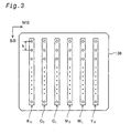
- Fig. 3 is an explanatory diagram showing the nozzle array on the bottom surface of the print head 36.
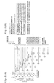
- Figs. 4(A) and 4(B) are explanatory diagrams showing the basic conditions for general dot recording mode.
- Figs. 5(A) and 5(B) are explanatory diagrams showing the basic conditions for overlap recording mode.
- Fig. 6 is an explanatory diagram showing the scanning parameters of the first embodiment.
- Fig. 7 is an explanatory diagram showing ordinal numbers of the nozzles that record respective raster lines on each pass in the first embodiment.
- Fig. 8 is an explanatory diagram showing the scanning parameters for a comparative example.
- Fig. 9 is an explanatory diagram showing ordinal numbers of the nozzles that record respective raster lines on each pass in the comparative example.
- Figs. 10(A) and 10(B) are explanatory diagrams showing partner nozzles of nozzle #1 and nozzles for recording adjacent raster lines above and below, pertaining to the first embodiment and the comparative example respectively.
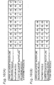
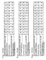
- Figs. 11(A)-11(C) are explanatory diagrams showing the scanning parameters of the second through fourth embodiments.
- Figs. 12(A)-12(C) are explanatory diagrams showing partner nozzles of nozzle #1 and nozzles for recording adjacent raster lines above and below, pertaining to the second through fourth embodiments and the comparative example respectively.
- Fig. 13 is an explanatory diagram showing the scanning parameters for the fifth embodiment.
- Fig. 14 is an explanatory diagram showing partner nozzles of nozzle #1 and nozzles for recording adjacent raster lines above and below, pertaining to the fifth embodiment.
- Figs. 15(A) and 15(B) are explanatory diagrams showing the scanning parameters for the sixth embodiment.
- Fig. 16 is an explanatory diagram showing ordinal numbers of the nozzles that record respective raster lines on each pass in the sixth embodiment.
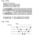
- Figs. 17(A) and 17(B) are explanatory diagrams showing the scanning parameters for the seventh embodiment.
- Fig. 18 is an explanatory diagram showing ordinal numbers of the nozzles that record respective raster lines on each pass in the seventh embodiment.
- Fig. 1 is a general oblique view showing the main structure of a color ink jet printer 20 used as a embodiment of the present invention.
- This printer 20 is equipped with a paper stacker 22, a paper feed roll 24 that is driven by a step motor not shown, a platen 26, a carriage 28, a step motor 30, a ribbed belt 32 that is driven by this step motor 30, and a guide rail 34 for the carriage 28.
- a print head 36 equipped with numerous nozzles is mounted on this carriage 28.
- the printing paper P is taken up onto a paper feed roller 24 from the paper stacker 22, and is transported in the sub-scan direction on the surface of the platen 26.
- the carriage 28 is pulled by a pulling belt 32 that is driven by the step motor 30, and is thus moved in the main scan direction along the guide rail 34.
- the main scan direction is perpendicular to the sub-scan direction.
- Fig. 2 is a block diagram showing the electrical configuration of the printer 20.
- the printer 20 is equipped with a receiving buffer memory 50 for receiving signals supplied from the host computer 100, an image buffer 52 that stores printing data, and a system controller 54 that controls operation of the entire printer 20.
- the system controller 54 are coupled to a main scan driver 61 that drives the carriage motor 30, a sub-scan driver 62 that drives the paper feed motor 31, and a head driver 63 that drives the print head 36.
- the printer driver (not shown) of the host computer 100 sets various parameter values that control printing operations based on the recording mode that has been specified by the user (described below). This printer driver also generates printing data for performing printing according to this recording mode based on these parameter values, and the data is transferred to the printer 20. The printing data thus transferred is temporarily stored in the receiving buffer memory 50.
- the system controller 54 in the printer 20 reads the required data from the printing data in the receiving buffer memory 50, and control signals are sent to respective drivers 61, 62 and 63 based on this data.
- the printing data received by the receiving buffer memory 50 is then divided into each color component and the image data of the various resulting color components is stored in the image buffer 52.
- the head driver 63 reads the image data for each color component from the image buffer 52 in accordance with the control signals from the system controller 54, and the nozzle array for each color situated on the print head 36 is driven in accordance therewith.
- the head driver 63 can generate numerous different types of drive signal waveforms. The internal configuration and functioning of the head driver 63 will be described later in detail.
- Fig. 3 is an explanatory diagram showing the nozzle array provided on the lower surface of the print head 36.
- black ink nozzle group K D for discharging black ink
- dark cyan ink nozzle group C D for discharging dark cyan ink
- light cyan ink nozzle group C L for discharging light cyan ink
- dark magenta ink nozzle group M D for discharging dark magenta ink
- light magenta ink nozzle group M L for discharging light magenta ink
- yellow ink nozzle group Y D for discharging yellow ink.
- the first large upper case letter in the designations of the nozzle groups designate the ink color, and the suffix "D” denotes ink with comparatively high density, whereas the suffix "L” denotes ink of comparatively low density.
- the numerous nozzles of each nozzle group are arranged with a constant nozzle pitch k along the sub-scan direction SS.
- the nozzle pitch k is set to a value that is an integral multiple of the print resolution (referred to as "dot pitch").
- piezo-electric elements (not shown in Figs.) are provided as drive elements that drive each of the nozzles, thereby causing discharge of ink droplets.
- the print head 36 travels along the main scan direction MS along with the carriage 28 (Fig. 1), and as this occurs, ink droplets are discharged from each nozzle.
- Figs. 4(A) and 4(B) are explanatory diagrams showing the basic parameters for ordinary dot printing modes.
- Fig. 4(A) shows an example of the sub-scan feeding when four nozzles are used, and Fig. 4(B) shows the parameters for the recording mode thereof.
- the solid circles enclosing the numbers denote the positions of the four nozzles in the sub-scan direction on each pass.
- the term "pass" refers to a single main scan.
- the numerals 0-3 enclosed in circles denote the nozzle numbers.
- the positions of the four nozzles move in the sub-scan direction after completion of a single main scan. Actually, feeding in the sub-scan direction is achieved by movement of the paper carried out by the paper feed motor 31 (Fig. 2).
- the sub-scan feed amount L in this example is a constant value of four dots. Consequently, when sub-scan feeding occurs, the positions of the four nozzles shift four dots in the sub-scan direction. All of the dot positions (also referred to as "pixel positions") on each of the raster lines in a single main scan is serviced by the nozzle. In this specification, the number of main scans occurring on each raster line (referred to also as “main scan line”) is referred to as the "scan repeat number S".
- the numbers of the nozzles that record dots on each raster line are indicated. Actual dot recording is prohibited on the raster lines that are drawn by broken lines extending to the right in the main scan direction from the circle indicating nozzle positions in the sub-scan direction because at least one of the previous and subsequent raster lines cannot be recorded.
- the raster lines that are drawn by solid lines extending in the main scan direction are in regions where the previous and subsequent raster lines can be recorded with dots.
- the region where actual recording is carried out in this manner is referred to as the effective recording region below (also referred to as "effective printing region", "printing execution region” and “recording execution region”).
- the dot recording mode parameters includes a nozzle pitch k [dots], a working nozzle number N, a scan repeat number S, an effective nozzle number Neff, and sub-scan feed amounts L [dots].
- the nozzle pitch k is 3 dots
- the working nozzle number N is 4.
- the working nozzle number N is the number of nozzles actually used among the multiple nozzles mounted.
- the scan repeat number S refers to the number of repetitions of main scans on each raster line. For example, when the scan repeat number S is 2, main scanning is executed twice on each raster line. Ordinarily, the dots are formed intermittently at every other dot positions for a single scan.
- the scan repeat number S is 1, and the effective nozzle number Neff is a value obtained by dividing the working nozzle number N by the scan repeat number S. This effective nozzle number Neff can be thought of as the net number of raster lines on which dot recording are completed by a single main scan.
- the table of Fig. 4(B) includes the sub-scan feed amount L for each pass, the summation ⁇ L thereof, and a nozzle offset F.
- offset F is a value that expresses the separation of the nozzle positions in the sub-scan direction in units of dots relative to reference positions, taken as offset 0, which are periodic positions of the nozzles at the initial pass 1 (the position of every fourth dot in Fig. 4(A)). For example, as shown in Fig. 4(A), after pass 1, the position of the nozzles shifts by the sub-scan feed amount L (4 dots) in the sub-scan direction. On the other hand, the nozzle pitch k is 3 dots.
- the offset F of the nozzles in pass 2 is 1 (Fig. 4(A)).
- the offset F is zero.
- the offset F is given by the remainder ( ⁇ L)%k obtained by dividing the summation ⁇ L of the sub-scan feed amounts L by the nozzle pitch k.
- the operator "%" expresses the remainder of the division.
- the initial nozzle positions are considered periodic positions, and the offset F can be thought of as expressing the amount of positional shift from the initial positions of the nozzles.
- the scan repeat number S is 1, the following conditions are required so that there are no duplications or omissions in the recording of raster lines in the effective recording region:
- Figs. 5(A) and 5(B) are explanatory diagrams showing the basic conditions for a dot recording mode where the scan repeat number S is 2 or greater. When the scan repeat number S is 2 or greater, main scanning is carried out s times on the same raster line.
- the dot recording mode with the scan repeat number S of 2 or greater is referred to as an "overlap mode".
- the parameters of the dot recording mode shown in Figs. 5(A) and 5(B) are different from that shown in Fig. 4(B) in the scan repeat number S and sub-scan feed amount L.
- the sub-scan feed amount L in the dot recording mode of Figs. 5(A) and 5(B) is a constant value of 2 dots.
- the position of the nozzles on the even numbered passes is indicated by diamond shapes in Fig. 5(A).
- the dot positions recorded on even number passes are shifted by one dot in the main scan direction relative to the dot positions recorded on odd number passes.
- the dots on the raster line are recorded intermittently by two different nozzles.
- the top-most raster line in the effective recording range is intermittently recorded at every other dot with nozzle #2 on pass 2, and is intermittently recorded at every other dot by nozzle #0 on pass 5.
- the nozzles are driven with intermittent timing in order to prevent recording of (S-1) dot after recording of one dot during the one main scan.
- the overlap mode in which intermittent pixel positions on a raster line are subject to dot recording during each main scan pass is referred to as "intermittent overlap mode". All pixel positions, instead of intermittent pixel positions, on a raster line may be serviced during each main scan. Specifically, when S main scans are carried out on a single raster line, overlapping of dots on the same pixel position can be allowed. This type of overlap mode is referred to as “superimposed overlap mode" or "total overlap mode".
- the positions on the same raster recorded by plural nozzles are shifted with respect to each other in the main scan direction, and so the shift amount in the main scan direction for each main scan can be conceived in various other ways in addition to that shown in Fig. 5(A).
- the dot positions indicated by circles can be recorded on pass 2 without shifting in the main scanning direction
- dot positions indicated by the diamond shapes can be recorded on pass 5 by allowing a shift in the main scan direction.
- the bottom-most row of the table of Fig. 5(B) shows the offset F for each pass in one cycle.
- One cycle includes six passes, and each value of the offset F in the range of 0-2 appears twice from pass 2 to pass 7.
- the change in offset F in the three passes from pass 2 to pass 4 is the same as the change in offset F in the three passes from pass 5 to pass 7.
- the six passes constituting one cycle can be divided into two sub-cycles, each including three passes. In this case, one cycle is completed by a repetition of s sub-cycles.
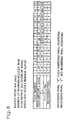
- Fig. 6 is an explanatory diagram showing the scanning parameters of the first embodiment.
- This recording mode is an overlap mode in which the nozzle pitch k is 6 dots, the working nozzle number N is 48, the scan repeat number S is 2 and the effective nozzle number Neff is 24.
- the table in Fig. 6 shows the parameters related to each of pass 1 to pass 13.
- the feed amounts of the 12 sub-scans constituting one cycle are divided into two groups each including 6 sub-scans. The two groups have different arrangements, or sequences, of sub-scan feed amounts.
- the table of Fig. 6 also shows the summation ⁇ L of the sub-scan feed amounts L up to each pass, and the offset F. From these parameters, it is clear that the recording mode of the first embodiment satisfies the conditions c1' to c3' described above.
- the pixel positions to be recorded in each pass are indicated at the bottom-most row of the table of Fig. 6. In this row, "0" denotes that the odd numbered pixel positions in this pass are to be recorded, and "1" denotes that the even numbered pixel positions are to be recorded.
- an intermitted overlap mode is adopted in which every other pixel positions are to be recorded intermittently.
- the first embodiment can be used in bi-directional printing or uni-directional printing.
- bi-directional printing the even numbered passes are carried out in the forward direction, and the odd numbered passes are carried out in the reverse direction.
- uni-directional printing each pass is always carried out in the forward direction. This situation is the same as for the other subsequent embodiments.
- Fig. 7 shows the ordinal numbers of the nozzles that record raster lines in each pass in the first embodiment.
- the term "raster line number" shown at the left in Fig. 7 are ordinal numbers starting from the top-most end position at which the nozzles of the print head 36 are positioned; the top-most end position may be in a region where recording is not possible (Fig. 5(A)).
- the upper 234 raster lines are omitted to simplify the Fig., and only raster lines 235-275 are shown.
- the nozzles that record at odd numbered pixel positions are indicated by solid square boxes, and the nozzles that record at even numbered pixel positions are indicated by broken square boxes.
- recording of dots on each raster line is performed with two different nozzles; one nozzle for recording at odd numbered pixel positions and another nozzle for recording at even numbered pixel positions.
- the even numbered pixel positions are recorded by nozzle #30 in pass 4
- the odd numbered pixel positions are recorded by nozzle #1 in pass 0.
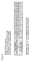
- Fig. 8 is an explanatory diagram showing the scanning parameters of a comparative example.
- the recording mode of the comparative example is the same as that of the first embodiment, with the exception that the sub-scan feed amount sequence is different.
- the sequence of the former six sub-scan feed amounts for passes 2-7 is the same as that of the latter six sub-scan feed amounts for passes 8-13.
- the recording mode of the comparative example is an overlap mode that satisfies the aforementioned conditions c1' to c3'.
- Fig. 9 shows the ordinal numbers of the nozzles that record raster lines in each pass in the comparative example.
- raster lines 229-275 are shown as in Fig. 7.
- the combinations of nozzles that record dots on each raster line are fixed.
- the nozzle that records the same raster line as nozzle #1 is always nozzle #25
- the nozzle that records on the same raster line as nozzle #2 is always nozzle #26.
- nozzle pair The combination of two nozzles that record the same raster line in an overlap mode when the scan repeat number S is 2 is referred to below as a "nozzle pair.”
- the nozzle that constitutes a nozzle pair with a certain nozzle is referred to as the "partner nozzle.”
- partner nozzle In the first embodiment shown in Fig. 7, a nozzle pair is formed by nozzle #1 and nozzle #30 that record on the 244th raster line.
- nozzle #28 and nozzle #26 are present in addition to nozzle #30 as partner nozzles that form a nozzle pair together with nozzle #1.
- Figs. 10(A) and 10(B) are explanatory diagrams showing the partner nozzles for nozzle #1 and upper- and lower-adjacent raster line recording nozzle each nozzle pair, pertaining to the first embodiment and comparative example.
- the term "upper-adjacent raster line recording nozzle” refers to the nozzle that is used for recording the raster line just above a particular raster line that is to be recorded by the nozzle pair.
- the term “lower-adjacent raster line recording nozzle” refers to the nozzle that is used for recording the raster line just below the particular raster line. For example, in Fig.
- nozzle #30 is the partner nozzle for nozzle #1
- nozzle #37 and nozzle #10 are upper-adjacent raster line recording nozzles.
- nozzle #37 alone is indicated as an upper-adjacent raster line recording nozzle when nozzle #30 is the partner nozzle, and nozzle #10 is omitted.
- all of the partner nozzles are indicated in the table of Figs. 10(A) and 10(B), some of the upper- and lower-adjacent raster line nozzles are omitted.
- nozzles As shown in Fig. 10(A), 8 different nozzles are used as partner nozzles for nozzle #1 in the first embodiment. On the other hand, in the comparative example shown in Fig. 10(B), only nozzle #25 is used as the partner nozzle for nozzle #1. These conditions apply also to nozzles other than nozzle #1.
- Figs. 11(A)-11(C) are explanatory diagrams showing the scanning parameters for the second through fourth embodiments.
- the recording mode for the second through fourth embodiments are the same as in the first embodiment, with the exception that the sub-scan feed amount sequences are different.
- Figs. 12(A)-12(C) are explanatory diagrams presenting a comparison of the partner nozzle for nozzle #1, and the upper- and lower-adjacent raster line recording nozzles with respect to the second through fourth embodiments.
- the second embodiment six different nozzles are used as the partner nozzle with nozzle #1.
- eight different nozzles are used as the partner nozzle for nozzle #1 in the same manner as in the first embodiment shown in Fig. 10(A). Consequently, in the second through fourth embodiments as well, there is the advantage that image quality degradation due to banding can be mitigated in overlap mode in the same manner as in the first embodiment.
- the recording mode to be adopted can be determined based on a comparison of printing results obtained by printing the same test image with the four different recording modes using the scanning parameters of the first through fourth embodiments, which are stored in advance in the memory (not shown) of the system controller (Fig. 2).
- Fig. 13 is an explanatory diagram showing the scanning parameters for the fifth embodiment.
- the recording mode for the fifth embodiment is the same as that for the first: through fourth embodiments, with the exception that the sub-scanning feed amount sequence is different.
- the fifth embodiment is different from the first through fourth embodiments in the range of the feed amount value. Specifically, a feed amount in the range of 8-62 dots is used for the fifth embodiment, whereas a feed amount range of 15-32 dots (first and second embodiments) or a feed amount range of 14-32 dots (third and fourth embodiments) is used for the first through fourth embodiments.
- the advantage of the fifth embodiment is as follows.
- the banding occurrence period tends to depend on the sub-scan feed amounts. Specifically, the banding occurrence period increases with increasing sub-scan feed amount, and decreases with decreasing sub-scan feed amount. Consequently, when the sub-scan feed amount is maintained within a comparatively narrow range as in the first through fourth embodiments, the banding occurrence period will be in a comparatively narrow range regardless of the cause of banding.
- the banding occurrence period is within a comparatively narrow range in this manner, it is easy to detect with the naked eye, and tends to degrade image quality.
- the banding occurrence period will also be distributed over a comparatively wide range, so that banding is not readily detected by the naked eye, which can mitigate image degradation.
- the ratio of the largest value and smallest value when a comparatively broad range of values are used for the sub-scan feed amount, it is preferable for the ratio of the largest value and smallest value to be about 4 or greater.
- the ratio of the largest value and smallest value is about 8 (62/8), whereas the ratio in the first through fourth embodiments is about 2 (32/15).
- Fig. 14 is an explanatory diagram showing a comparison of the partner nozzles for nozzle #1 and the upper- and lower-adjacent raster line recording nozzles in the fifth embodiment.
- 11 different nozzles are used for the partner nozzle for nozzle #1.
- more nozzle pairs are used in the fifth embodiment than in the first through fourth embodiments, which is preferable from the standpoint of mitigating image quality degradation due to the banding.
- Figs. 15(A) and 15(B) are explanatory diagrams showing the scanning parameters for the sixth embodiment.
- Fig. 16 is an explanatory diagram showing the ordinal numbers of the nozzles that record raster lines in each pass in the sixth embodiment.
- this recording mode is an overlap mode wherein the nozzle pitch k is 4 dots, the working nozzle number N is 48, the scan repeat number S is 2, and the effective nozzle number Neff is 24.
- the recording mode of the sixth embodiment is also characterized by having a modification pattern for the offset F shown in Fig. 15(B).
- the value of the offset F is increased by 1 ⁇ 0, 1, 2, 3 ⁇ , and is then decreased by 1 ⁇ 3, 2, 1, 0 ⁇ .
- the sub-scan feed amount sequence is not only different, but the offset F arrangement is also different. This stands in contrast to the offset F in the first through fifth embodiments above, where a constant sequence ⁇ 2, 5, 3, 1, 4, 0 ⁇ of the offset F is repeated.
- this offset F sequence it is possible to decrease cumulative errors in sub-scan feed.
- a sub-scan feed mechanism can be conceived wherein the cumulative error in sub-scan feed increases with increasing value of the offset F, and decreases with decreasing value of the offset F.
- the cumulative sub-scan feed error increases from passes 2-5 in Fig. 15(B), but decreases in passes 6-9. As a result, it is possible to further reduce banding.
- Figs. 17(A) and 17(B) are explanatory diagrams of the scanning parameters for the seventh embodiment.
- Fig. 18 is an explanatory diagram showing the ordinal numbers of the nozzles that record raster lines in each pass in the seventh embodiment.
- the recording mode is different from that of the sixth embodiment shown in Fig. 15(A) only in the sub-scan feed amounts.
- this mode has the second characteristic that the sequence of the offset F is different between the first half and the second half of one cycle. Consequently, the seventh embodiment can mitigate image degradation due to the banding in the same manner as in the sixth embodiment described above.
- the pattern of the offset F is reversed in the first half and second half of one cycle in the sixth and seventh embodiments, so that the patterns for the first half and second half are symmetrical.
- the sequence of the offset F need not be reversed in the second half relative to the first half, but it is preferable for the sub-scan feed amounts be established so that the sequence of the offset F is different in the first half and second half.
- the sequences of the offset F are reversed, the effect of decreasing banding due to cumulative error in sub-scan feeding described above can be further enhanced.
- the scan repeat number S is 2, but the present invention can be utilized in cases where the scan repeat number S is any integer of 2 or greater.
- the present invention can be used in cases where the nozzle pitch k [dots] is any integer of 2 or greater.
- the feed amounts of the S ⁇ k sub-scans are divided into S groups each including k feed amounts for consecutive k sub-scans, and at least one of the S groups of sub-scans has a different sequence of feed amounts from those of the other groups.
- the sub-scan feed amounts to be established so that the offset F arrangement for at least one of the S groups of sub-scans has a different arrangement from those of the other groups, and it is particularly desirable for the offset F arrangement to be reversed from those for its adjacent groups.
- an intermittent overlap mode is adopted, but it is also possible to use a complete overlap mode where all of the pixel positions on the main scan lines that are scanned can be serviced in each pass.
- the present invention can also be adopted for drum scanning type printers.
- drum scanning type printers the direction of drum rotation is the main scan direction, and the direction of carriage travel is the sub-scan direction.
- the present invention can be used not only with ink jet printers, but with printing devices in which printing onto the surface of a printing medium is carried out using a print head having multiple nozzles. These types of printing devices include facsimile devices and copy devices.
- part of the configuration that is realized in hardware can be converted into software, and conversely, part of the configuration that is realized in software can be converted into hardware.
- some of the functions of the system controller 54 (Fig. 2) can be implemented by the host computer 100.
- Computer programs that perform this type of function are offered in various types of computer readable recording media such as floppy disks and CD-ROMs.
- the host computer 100 reads the computer program from the recording medium, and transmits it to an internal memory device or external memory device.
- the computer program can be supplied to the host computer 100 from a program supply device via a communication path.
- the function of the computer program is executed, the computer program that has been stored in the internal memory device is executed by the microprocessor of the host computer 100.
- the computer program that has been stored on the storage medium can be directly executed by the host computer 100.
- the host computer 100 is a general term that includes a hardware device and operation system, and refers to a hardware device that is operated under the control of the operating system.
- the computer program executes various parts of the aforementioned functions in this host computer 100. Some of the above functions can also be executed by the operating system without using an application program.
- the term "computer readable recording medium” is not restricted to a portable recording medium such as a flexible disk or CD-ROM, and also includes internal storage devices in the computer such as RAM and ROM, as well as external storage devices attached to the computer, such as hard disks.
- the present invention can be employed in printers or facsimile devices that discharge ink from nozzles.
Landscapes
- Engineering & Computer Science (AREA)
- Quality & Reliability (AREA)
- Ink Jet (AREA)
- Dot-Matrix Printers And Others (AREA)
Abstract
Printing is carried out on a printing medium during main scanning
using a printing device which comprises a print head having one or more
nozzle arrays each including a plurality of nozzles for forming dots of same
color. The plurality of nozzles for forming dots of the same color have a
constant nozzle pitch k×D in the sub-scan direction, where k is an integer of
2 or greater and D is a dot pitch that corresponds to a printing resolution in
the sub-scan direction. Each main scan line is scanned S times, where S is
an integer of 2 or greater, using different nozzles. A combination of
different values is used as feed amounts for S×k sub-scans. When the feed
amounts for the S×k sub-scans are divided into S groups each containing k
feed amounts for consecutive k sub-scans, a sequence of sub-scan feed
amounts in at least one of the S groups of sub-scans is different from
sequences in the other groups.
Description
The present invention relates to a printing technology using a print
head having multiple nozzles.
In recent years, ink jet printers that discharge ink from a head are
widely used as computer output devices. Ink jet printers employ a print
head having multiple nozzles for each ink.
One printing mode is established whereby sub-scan feed amounts and
the number of nozzles used is controlled during printing with the printer.
In such cases, there is some constraint in terms of sub-scanning feed
amounts and number of nozzles used in order to perform recording at pixel
positions on the printing medium without unnecessary duplications or
omissions.
In this connection, it is desirable that as many of the mounted nozzles
as possible are used in the execution of printing in order to improve printing
speed. Towards this end, numerous different values for the sub-scan feed
amount are used in combination in the technology described in JP-A-1998-278247
disclosed by the applicant of this application. In addition, this
document also describes an "overlap mode" in which recording of each main
scan line is completed in two or more main scans. With overlap mode in
which recording on each main scan line is completed in two main scans, the
respective main scan lines are each scanned with two different nozzles.
However, with previous overlap mode, there has been the problem
that there are restricted combinations of nozzles that carry out recording of
a single main scan line. For example, main scan lines that are recorded
using nozzle # 1 are always recorded with nozzle # 25, and main scan lines
that are recorded using nozzle # 2 are always recorded with nozzle # 26. The
number of nozzle combinations is thus restricted to one.
Because the number of combinations of nozzles used for recording a
single main scan line is restricted to one, striated regions of image quality
degradation referred to as "banding" appears in the main scan lines. For
example, due to manufacture differences in nozzles # 1 and #25 that perform
recording of the same main scan line, there are cases where dots are
recorded at shifted positions in the same direction along the sub-scanning
direction relative to the theoretical position (intended position). In such
cases, a gap (specifically, banding) arises between a main scan line and its
adjacent main scan line, resulting in image degradation.
This invention was developed in order to solve the above problems
with conventional technologies, and has an object of offering a technology
for mitigating image degradation in overlap mode.
In order to solve at least some of the problems described above, the
present invention carries out printing on a printing medium during main
scanning using a printing device which comprises a print head having one
or more nozzle arrays each including a plurality of nozzles for forming dots
of same color. The plurality of nozzles for forming dots of the same color
have a constant nozzle pitch k×D in the sub-scan direction, where k is an
integer of 2 or greater and D is a dot pitch that corresponds to a printing
resolution in the sub-scan direction. Each main scan line is scanned S times,
where S is an integer of 2 or greater, using different nozzles. A combination
of different values is used as feed amounts for S×k sub-scans. When the
feed amounts for the S×k sub-scans are divided into S groups each
containing k feed amounts for consecutive k sub-scans, a sequence of sub-scan
feed amounts in at least one of the S groups of sub-scans is different
from sequences in the other groups.
In the present invention, because the sequences of the S groups of
sub-scan feed amounts are not the same, combinations of nozzles for
recording the same main scan line are not fixed to only one, and multiple
combinations are used. This results in reduction of banding and mitigation
of image quality degradation.
It is preferable that intermittent pixel positions at a ratio of 1 to S
pixels on a main scan line are serviced for dot formation in each of S main
scans performed on the main scan line, and all of the pixel positions on the
main scan line are serviced for dot formation by the S main scans.
In this case, the banding caused by the configuration where the
combinations of nozzles for recording the same main scan line are fixed to
only one tends to be particularly noticeable. Consequently, the
aforementioned effect is particularly remarkable in such cases.
It is preferable that a ratio of the largest and smallest values of the
S×k sub-scan feed amounts is set at about 4 or greater.
In this configuration, even if banding should occur for whatever
reason, the banding occurrence period varies with the value of the sub-scan
feed amount, and so banding is not readily seen. The image quality
degradation is further reduced consequently.
When a offset F is defined as a remainder obtained by dividing a
cumulative value of sub-scan feed amounts by the integer k, a sequence of
the offset F for at least one of the S groups of sub-scan feed amounts may be
different from sequences for the other groups.
The offset F sequence is related very strongly to cumulative error
occurring in the sub-scan feed, and using different offset F sequences tends
to decrease cumulative error in the sub-scan feed, allowing mitigation of
banding.
It is preferable that the sequence of the offset F for each group of sub-scan
feed amounts is reversed from the sequence of the offset F for adjacent
groups.
In this configuration, it is possible to additionally decrease the
cumulative error in the sub-scan feed, thus making it possible to
additionally reducing banding.
The effect of the above configuration related to the offset F sequence
is particularly remarkable when dots are formed with a print head using
pigment ink.
The present invention can be realized in various configurations, such
as a printing device and printing method, a computer program for
implementing the functions of the device or method, a computer readable
recording medium storing the computer program, and a data signal
embodied in a carrier wave that includes the computer program.
Fig. 1 is a general oblique view showing the main structure of a color
ink jet printer 20 used as an embodiment of the present invention.
Fig. 2 is a block diagram showing the electrical configuration of the
printer 20.
Fig. 3 is an explanatory diagram showing the nozzle array on the
bottom surface of the print head 36.
Figs. 4(A) and 4(B) are explanatory diagrams showing the basic
conditions for general dot recording mode.
Figs. 5(A) and 5(B) are explanatory diagrams showing the basic
conditions for overlap recording mode.
Fig. 6 is an explanatory diagram showing the scanning parameters of
the first embodiment.
Fig. 7 is an explanatory diagram showing ordinal numbers of the
nozzles that record respective raster lines on each pass in the first
embodiment.
Fig. 8 is an explanatory diagram showing the scanning parameters
for a comparative example.
Fig. 9 is an explanatory diagram showing ordinal numbers of the
nozzles that record respective raster lines on each pass in the comparative
example.
Figs. 10(A) and 10(B) are explanatory diagrams showing partner
nozzles of nozzle # 1 and nozzles for recording adjacent raster lines above
and below, pertaining to the first embodiment and the comparative example
respectively.
Figs. 11(A)-11(C) are explanatory diagrams showing the scanning
parameters of the second through fourth embodiments.
Figs. 12(A)-12(C) are explanatory diagrams showing partner nozzles
of nozzle # 1 and nozzles for recording adjacent raster lines above and below,
pertaining to the second through fourth embodiments and the comparative
example respectively.
Fig. 13 is an explanatory diagram showing the scanning parameters
for the fifth embodiment.
Fig. 14 is an explanatory diagram showing partner nozzles of nozzle
# 1 and nozzles for recording adjacent raster lines above and below,
pertaining to the fifth embodiment.
Figs. 15(A) and 15(B) are explanatory diagrams showing the scanning
parameters for the sixth embodiment.
Fig. 16 is an explanatory diagram showing ordinal numbers of the
nozzles that record respective raster lines on each pass in the sixth
embodiment.
Figs. 17(A) and 17(B) are explanatory diagrams showing the scanning
parameters for the seventh embodiment.
Fig. 18 is an explanatory diagram showing ordinal numbers of the
nozzles that record respective raster lines on each pass in the seventh
embodiment.
Modes of implementation of the present invention are described below
based on embodiments in the following order.
Fig. 1 is a general oblique view showing the main structure of a color
ink jet printer 20 used as a embodiment of the present invention. This
printer 20 is equipped with a paper stacker 22, a paper feed roll 24 that is
driven by a step motor not shown, a platen 26, a carriage 28, a step motor
30, a ribbed belt 32 that is driven by this step motor 30, and a guide rail 34
for the carriage 28. A print head 36 equipped with numerous nozzles is
mounted on this carriage 28.
The printing paper P is taken up onto a paper feed roller 24 from the
paper stacker 22, and is transported in the sub-scan direction on the surface
of the platen 26. The carriage 28 is pulled by a pulling belt 32 that is driven
by the step motor 30, and is thus moved in the main scan direction along the
guide rail 34. The main scan direction is perpendicular to the sub-scan
direction.
Fig. 2 is a block diagram showing the electrical configuration of the
printer 20. The printer 20 is equipped with a receiving buffer memory 50
for receiving signals supplied from the host computer 100, an image buffer
52 that stores printing data, and a system controller 54 that controls
operation of the entire printer 20. The system controller 54 are coupled to a
main scan driver 61 that drives the carriage motor 30, a sub-scan driver 62
that drives the paper feed motor 31, and a head driver 63 that drives the
print head 36.
The printer driver (not shown) of the host computer 100 sets various
parameter values that control printing operations based on the recording
mode that has been specified by the user (described below). This printer
driver also generates printing data for performing printing according to this
recording mode based on these parameter values, and the data is
transferred to the printer 20. The printing data thus transferred is
temporarily stored in the receiving buffer memory 50. The system
controller 54 in the printer 20 reads the required data from the printing
data in the receiving buffer memory 50, and control signals are sent to
respective drivers 61, 62 and 63 based on this data.
The printing data received by the receiving buffer memory 50 is then
divided into each color component and the image data of the various
resulting color components is stored in the image buffer 52. The head driver
63 reads the image data for each color component from the image buffer 52
in accordance with the control signals from the system controller 54, and the
nozzle array for each color situated on the print head 36 is driven in
accordance therewith. The head driver 63 can generate numerous different
types of drive signal waveforms. The internal configuration and functioning
of the head driver 63 will be described later in detail.
Fig. 3 is an explanatory diagram showing the nozzle array provided
on the lower surface of the print head 36. There are provided, on the bottom
surface of the head 36, black ink nozzle group KD for discharging black ink,
dark cyan ink nozzle group CD for discharging dark cyan ink, light cyan ink
nozzle group CL for discharging light cyan ink, dark magenta ink nozzle
group MD for discharging dark magenta ink, light magenta ink nozzle group
ML for discharging light magenta ink, and yellow ink nozzle group YD for
discharging yellow ink.
The first large upper case letter in the designations of the nozzle
groups designate the ink color, and the suffix "D" denotes ink with
comparatively high density, whereas the suffix "L" denotes ink of
comparatively low density.
The numerous nozzles of each nozzle group are arranged with a
constant nozzle pitch k along the sub-scan direction SS. The nozzle pitch k
is set to a value that is an integral multiple of the print resolution (referred
to as "dot pitch"). In addition, piezo-electric elements (not shown in Figs.)
are provided as drive elements that drive each of the nozzles, thereby
causing discharge of ink droplets. During printing, the print head 36
travels along the main scan direction MS along with the carriage 28 (Fig. 1),
and as this occurs, ink droplets are discharged from each nozzle.
Before presenting a detailed description of the recording mode used in
the embodiments of the present invention, the basic parameters used in
ordinary recording mode will be described. In this specification, the terms
"recording mode" and "printing mode" are synonymous.
Figs. 4(A) and 4(B) are explanatory diagrams showing the basic
parameters for ordinary dot printing modes. Fig. 4(A) shows an example of
the sub-scan feeding when four nozzles are used, and Fig. 4(B) shows the
parameters for the recording mode thereof. In Fig. 4(A), the solid circles
enclosing the numbers denote the positions of the four nozzles in the sub-scan
direction on each pass. The term "pass" refers to a single main scan.
The numerals 0-3 enclosed in circles denote the nozzle numbers. The
positions of the four nozzles move in the sub-scan direction after completion
of a single main scan. Actually, feeding in the sub-scan direction is achieved
by movement of the paper carried out by the paper feed motor 31 (Fig. 2).
As indicated at the left side of Fig. 4(A), the sub-scan feed amount L
in this example is a constant value of four dots. Consequently, when sub-scan
feeding occurs, the positions of the four nozzles shift four dots in the
sub-scan direction. All of the dot positions (also referred to as "pixel
positions") on each of the raster lines in a single main scan is serviced by
the nozzle. In this specification, the number of main scans occurring on
each raster line (referred to also as "main scan line") is referred to as the
"scan repeat number S".
At the right side of Fig. 4(A), the numbers of the nozzles that record
dots on each raster line are indicated. Actual dot recording is prohibited on
the raster lines that are drawn by broken lines extending to the right in the
main scan direction from the circle indicating nozzle positions in the sub-scan
direction because at least one of the previous and subsequent raster
lines cannot be recorded. On the other hand, the raster lines that are drawn
by solid lines extending in the main scan direction are in regions where the
previous and subsequent raster lines can be recorded with dots. The region
where actual recording is carried out in this manner is referred to as the
effective recording region below (also referred to as "effective printing
region", "printing execution region" and "recording execution region").
In Fig. 4(B), each of the parameters related to this dot recording mode
are shown. The dot recording mode parameters includes a nozzle pitch k
[dots], a working nozzle number N, a scan repeat number S, an effective
nozzle number Neff, and sub-scan feed amounts L [dots].
In the example of Figs. 4(A) and 4(B), the nozzle pitch k is 3 dots, and
the working nozzle number N is 4. The working nozzle number N is the
number of nozzles actually used among the multiple nozzles mounted. The
scan repeat number S refers to the number of repetitions of main scans on
each raster line. For example, when the scan repeat number S is 2, main
scanning is executed twice on each raster line. Ordinarily, the dots are
formed intermittently at every other dot positions for a single scan. In Figs.
4(A) and 4(B), the scan repeat number S is 1, and the effective nozzle
number Neff is a value obtained by dividing the working nozzle number N
by the scan repeat number S. This effective nozzle number Neff can be
thought of as the net number of raster lines on which dot recording are
completed by a single main scan.
The table of Fig. 4(B) includes the sub-scan feed amount L for each
pass, the summation ΣL thereof, and a nozzle offset F. The term "offset F"
used herein is a value that expresses the separation of the nozzle positions
in the sub-scan direction in units of dots relative to reference positions,
taken as offset 0, which are periodic positions of the nozzles at the initial
pass 1 (the position of every fourth dot in Fig. 4(A)). For example, as shown
in Fig. 4(A), after pass 1, the position of the nozzles shifts by the sub-scan
feed amount L (4 dots) in the sub-scan direction. On the other hand, the
nozzle pitch k is 3 dots. Consequently, the offset F of the nozzles in pass 2 is
1 (Fig. 4(A)). Similarly, the positions of the nozzles on pass 3 have moved by
ΣL = 8 dots from the initial positions, and the offset F is 2 consequently.
The positions of the nozzles on pass 4 have moved ΣL = 12 dots from the
initial positions, and the offset F is 0. Because the offset F of the nozzles
returns to 0 on pass 4 after the third sub-scan feed, three sub-scans are
considered to constitute one cycle of sub-scans. By repeating this cycle, all
of the dots on the raster lines of the effective recording area can be recorded.
As is clear from the example of Figs. 4(A) and 4(B), when the nozzle
positions are separated from the initial positions by an integral multiple of
the nozzle pitch k, the offset F is zero. In addition, the offset F is given by
the remainder (ΣL)%k obtained by dividing the summation ΣL of the sub-scan
feed amounts L by the nozzle pitch k. The operator "%" expresses the
remainder of the division. The initial nozzle positions are considered
periodic positions, and the offset F can be thought of as expressing the
amount of positional shift from the initial positions of the nozzles.
If the scan repeat number S is 1, the following conditions are required
so that there are no duplications or omissions in the recording of raster lines
in the effective recording region:
The above conditions can be understood when envisioned in the
following manner. Because there are (k-1) raster lines between adjacent
nozzles, in order to return to the reference position of the nozzles (position
at which offset F=0) upon recording on these (k-1) raster lines in one cycle,
the number of sub-feeds in one cycle must be k. If the number of sub-feeds
in one cycle is less than k, there will be omissions in the recorded raster
lines, and if the number of sub-scan feeds in one cycle is greater than k,
there will be overlap in the recorded raster lines. The first condition c1
above is thus established.
When the number of sub-scans in one cycle is k, there will be no
omissions or duplications in recorded raster lines when the offset value F
after each sub-scan feed assumes different values within the range 0 to (k-1).
The second condition c2 above is thus established.
If the first and second conditions above are satisfied, then k raster
lines are recorded by the respective N nozzles during one cycle.
Consequently, N×k raster lines are recorded during one cycle. On the other
hand, if the third condition c3 is satisfied, then as shown in Fig. 4(A), the
nozzle position after one cycle (after k number of sub-scan feeds) is
separated by N×k raster lines from the initial nozzle position. Consequently,
omissions or duplications in the recorded raster lines can be avoided in the
range of these N×k raster lines if the first through third conditions c1 to c3
are satisfied.
Figs. 5(A) and 5(B) are explanatory diagrams showing the basic
conditions for a dot recording mode where the scan repeat number S is 2 or
greater. When the scan repeat number S is 2 or greater, main scanning is
carried out s times on the same raster line. The dot recording mode with
the scan repeat number S of 2 or greater is referred to as an "overlap mode".
The parameters of the dot recording mode shown in Figs. 5(A) and
5(B) are different from that shown in Fig. 4(B) in the scan repeat number S
and sub-scan feed amount L. As is clear from Fig. 5(A), the sub-scan feed
amount L in the dot recording mode of Figs. 5(A) and 5(B) is a constant
value of 2 dots. The position of the nozzles on the even numbered passes is
indicated by diamond shapes in Fig. 5(A). Ordinarily, as shown to the right
in Fig. 5(A), the dot positions recorded on even number passes are shifted by
one dot in the main scan direction relative to the dot positions recorded on
odd number passes. Consequently, the dots on the raster line are recorded
intermittently by two different nozzles. For example, the top-most raster
line in the effective recording range is intermittently recorded at every other
dot with nozzle # 2 on pass 2, and is intermittently recorded at every other
dot by nozzle # 0 on pass 5. With this overlap mode, the nozzles are driven
with intermittent timing in order to prevent recording of (S-1) dot after
recording of one dot during the one main scan.
The overlap mode in which intermittent pixel positions on a raster
line are subject to dot recording during each main scan pass is referred to as
"intermittent overlap mode". All pixel positions, instead of intermittent
pixel positions, on a raster line may be serviced during each main scan.
Specifically, when S main scans are carried out on a single raster line,
overlapping of dots on the same pixel position can be allowed. This type of
overlap mode is referred to as "superimposed overlap mode" or "total overlap
mode".
With the intermittent overlap mode, the positions on the same raster
recorded by plural nozzles are shifted with respect to each other in the main
scan direction, and so the shift amount in the main scan direction for each
main scan can be conceived in various other ways in addition to that shown
in Fig. 5(A). For example, the dot positions indicated by circles can be
recorded on pass 2 without shifting in the main scanning direction, and dot
positions indicated by the diamond shapes can be recorded on pass 5 by
allowing a shift in the main scan direction.
The bottom-most row of the table of Fig. 5(B) shows the offset F for
each pass in one cycle. One cycle includes six passes, and each value of the
offset F in the range of 0-2 appears twice from pass 2 to pass 7. In addition,
the change in offset F in the three passes from pass 2 to pass 4 is the same
as the change in offset F in the three passes from pass 5 to pass 7. As
shown at the left in Fig. 5(A), the six passes constituting one cycle can be
divided into two sub-cycles, each including three passes. In this case, one
cycle is completed by a repetition of s sub-cycles.
In general, when the scan repeat number S is a positive integer of 2
or greater, the first through third conditions c1-c3 indicated above are
rewritten as c1'-c3' below.
Fig. 6 is an explanatory diagram showing the scanning parameters of
the first embodiment. This recording mode is an overlap mode in which the
nozzle pitch k is 6 dots, the working nozzle number N is 48, the scan repeat
number S is 2 and the effective nozzle number Neff is 24.
The table in Fig. 6 shows the parameters related to each of pass 1 to
pass 13. The feed amount L (dots) for each of the 12 (=S×k) sub-scans that
constitute one cycle is 20, 21, 22, 28, 27, 32, 32, 27, 28, 16, 15 and 20; plural
different values are used here. As is indicated by the broken line between
pass 7 and pass 8, the feed amounts of the 12 sub-scans constituting one
cycle are divided into two groups each including 6 sub-scans. The two
groups have different arrangements, or sequences, of sub-scan feed amounts.
The table of Fig. 6 also shows the summation ΣL of the sub-scan feed
amounts L up to each pass, and the offset F. From these parameters, it is
clear that the recording mode of the first embodiment satisfies the
conditions c1' to c3' described above.
The pixel positions to be recorded in each pass are indicated at the
bottom-most row of the table of Fig. 6. In this row, "0" denotes that the odd
numbered pixel positions in this pass are to be recorded, and "1" denotes
that the even numbered pixel positions are to be recorded. In the first
embodiment, an intermitted overlap mode is adopted in which every other
pixel positions are to be recorded intermittently.
The first embodiment can be used in bi-directional printing or uni-directional
printing. In bi-directional printing, the even numbered passes
are carried out in the forward direction, and the odd numbered passes are
carried out in the reverse direction. In uni-directional printing, each pass is
always carried out in the forward direction. This situation is the same as
for the other subsequent embodiments.
Fig. 7 shows the ordinal numbers of the nozzles that record raster
lines in each pass in the first embodiment. The term "raster line number"
shown at the left in Fig. 7 are ordinal numbers starting from the top-most
end position at which the nozzles of the print head 36 are positioned; the
top-most end position may be in a region where recording is not possible
(Fig. 5(A)). The upper 234 raster lines are omitted to simplify the Fig., and
only raster lines 235-275 are shown. The nozzles that record at odd
numbered pixel positions are indicated by solid square boxes, and the
nozzles that record at even numbered pixel positions are indicated by
broken square boxes. It can be seen that recording of dots on each raster
line is performed with two different nozzles; one nozzle for recording at odd
numbered pixel positions and another nozzle for recording at even
numbered pixel positions. For example, with the 244th raster line, the even
numbered pixel positions are recorded by nozzle # 30 in pass 4, and the odd
numbered pixel positions are recorded by nozzle # 1 in pass 0.
Fig. 8 is an explanatory diagram showing the scanning parameters of
a comparative example. The recording mode of the comparative example is
the same as that of the first embodiment, with the exception that the sub-scan
feed amount sequence is different. In addition, among the feed
amounts of the 12 (=S×k) sub-scans constituting one cycle, the sequence of
the former six sub-scan feed amounts for passes 2-7 is the same as that of
the latter six sub-scan feed amounts for passes 8-13. The recording mode of
the comparative example is an overlap mode that satisfies the
aforementioned conditions c1' to c3'.
Fig. 9 shows the ordinal numbers of the nozzles that record raster
lines in each pass in the comparative example. In Fig. 9 as well, raster lines
229-275 are shown as in Fig. 7. In the comparative example, the
combinations of nozzles that record dots on each raster line are fixed. For
example, the nozzle that records the same raster line as nozzle # 1 is always
nozzle # 25, and the nozzle that records on the same raster line as nozzle # 2
is always nozzle # 26. On the other hand, in the first embodiment shown in
Fig. 7, there are three nozzles that record on the same raster line as nozzle
#1: nozzle #30 (244th raster line), nozzle 28 (260th raster line) and nozzle 26
(275th raster line).
The combination of two nozzles that record the same raster line in an
overlap mode when the scan repeat number S is 2 is referred to below as a
"nozzle pair." The nozzle that constitutes a nozzle pair with a certain nozzle
is referred to as the "partner nozzle." In the first embodiment shown in Fig.
7, a nozzle pair is formed by nozzle # 1 and nozzle # 30 that record on the
244th raster line. In addition, nozzle # 28 and nozzle # 26 are present in
addition to nozzle # 30 as partner nozzles that form a nozzle pair together
with nozzle # 1.
Figs. 10(A) and 10(B) are explanatory diagrams showing the partner
nozzles for nozzle # 1 and upper- and lower-adjacent raster line recording
nozzle each nozzle pair, pertaining to the first embodiment and comparative
example. The term "upper-adjacent raster line recording nozzle" refers to
the nozzle that is used for recording the raster line just above a particular
raster line that is to be recorded by the nozzle pair. The term "lower-adjacent
raster line recording nozzle" refers to the nozzle that is used for
recording the raster line just below the particular raster line. For example,
in Fig. 7, the 244th raster line is recorded by nozzle # 1 and nozzle # 30, and
the upper adjacent raster line is recorded by nozzle # 37 and nozzle # 10. In
this case, nozzle # 30 is the partner nozzle for nozzle # 1, and nozzle # 37 and
nozzle # 10 are upper-adjacent raster line recording nozzles. In Fig. 10(A),
nozzle # 37 alone is indicated as an upper-adjacent raster line recording
nozzle when nozzle # 30 is the partner nozzle, and nozzle # 10 is omitted.
Although all of the partner nozzles are indicated in the table of Figs. 10(A)
and 10(B), some of the upper- and lower-adjacent raster line nozzles are
omitted.
As shown in Fig. 10(A), 8 different nozzles are used as partner
nozzles for nozzle # 1 in the first embodiment. On the other hand, in the
comparative example shown in Fig. 10(B), only nozzle # 25 is used as the
partner nozzle for nozzle # 1. These conditions apply also to nozzles other
than nozzle # 1.
The nozzle pairs are fixed when the same sequence of feed amounts
for k (=6) sub-scans is repeated S(=2) times, as in the comparative example.
Because the nozzle pairs are always the same, image quality degradation
can occur. Specifically, if the dot forming positions of the nozzle pair is
shifted in opposite directions along the sub-scan direction relative to the
ideal position (intended position), "banding" will occur in the vicinity of the
raster line, resulting in the possibility of image quality degradation. On the
other hand, if different sequences of sub-scan feed amounts are used for the
two groups of k (=6) sub-scans, as in the first embodiment, then plural
nozzles are used as the partner nozzle for each nozzle. In such a case, dot
recording is carried out using various nozzle pairs, so that "banding" caused
by manufacture differences in the nozzles mentioned above will not readily
occur. Consequently, image quality degradation due to "banding" in overlap
mode can be mitigated.
Figs. 11(A)-11(C) are explanatory diagrams showing the scanning
parameters for the second through fourth embodiments. The recording
mode for the second through fourth embodiments are the same as in the
first embodiment, with the exception that the sub-scan feed amount
sequences are different. In addition, as is the case with the first
embodiment, different sub-sequences are used for the sub-scan feed
amounts for the first 6 passes 2-7, and the sub-scan feed amount sequence
for the latter 6 passes 8-13 among the 12 (=S×k) sub-scans constituting one
cycle.
Figs. 12(A)-12(C) are explanatory diagrams presenting a comparison
of the partner nozzle for nozzle # 1, and the upper- and lower-adjacent raster
line recording nozzles with respect to the second through fourth
embodiments. In the second embodiment, six different nozzles are used as
the partner nozzle with nozzle # 1. In addition, in the third and fourth
embodiments, eight different nozzles are used as the partner nozzle for
nozzle # 1 in the same manner as in the first embodiment shown in Fig.
10(A). Consequently, in the second through fourth embodiments as well,
there is the advantage that image quality degradation due to banding can
be mitigated in overlap mode in the same manner as in the first
embodiment.
Which of the first through fourth embodiments attains the highest
image quality depends on manufacture variation in each nozzle in the
printing device. Consequently, the recording mode to be adopted can be
determined based on a comparison of printing results obtained by printing
the same test image with the four different recording modes using the
scanning parameters of the first through fourth embodiments, which are
stored in advance in the memory (not shown) of the system controller (Fig.
2).
Fig. 13 is an explanatory diagram showing the scanning parameters
for the fifth embodiment. The recording mode for the fifth embodiment is
the same as that for the first: through fourth embodiments, with the
exception that the sub-scanning feed amount sequence is different. In
addition, as is the case with the first through fourth embodiments, different
sub-sequences are used for the sub-scan feed amounts for the first 6 passes
2-7, and the sub-scan feed amounts for the latter 6 passes 8-13 among the
12 (=S×k) sub-scans constituting one cycle.
The fifth embodiment is different from the first through fourth
embodiments in the range of the feed amount value. Specifically, a feed
amount in the range of 8-62 dots is used for the fifth embodiment, whereas a
feed amount range of 15-32 dots (first and second embodiments) or a feed
amount range of 14-32 dots (third and fourth embodiments) is used for the
first through fourth embodiments.
The advantage of the fifth embodiment is as follows. In general,
when banding occurs for any reason, the banding occurrence period tends to
depend on the sub-scan feed amounts. Specifically, the banding occurrence
period increases with increasing sub-scan feed amount, and decreases with
decreasing sub-scan feed amount. Consequently, when the sub-scan feed
amount is maintained within a comparatively narrow range as in the first
through fourth embodiments, the banding occurrence period will be in a
comparatively narrow range regardless of the cause of banding. When the
banding occurrence period is within a comparatively narrow range in this
manner, it is easy to detect with the naked eye, and tends to degrade image
quality. On the other hand, when the sub-scan feed amount occurs over a
comparatively broad range, as in the fifth embodiment, the banding
occurrence period will also be distributed over a comparatively wide range,
so that banding is not readily detected by the naked eye, which can mitigate
image degradation.
As shown in the fifth embodiment, when a comparatively broad range
of values are used for the sub-scan feed amount, it is preferable for the ratio
of the largest value and smallest value to be about 4 or greater. In the fifth
embodiment, the ratio of the largest value and smallest value is about 8
(62/8), whereas the ratio in the first through fourth embodiments is about 2
(32/15).
Fig. 14 is an explanatory diagram showing a comparison of the
partner nozzles for nozzle # 1 and the upper- and lower-adjacent raster line
recording nozzles in the fifth embodiment. In the fifth embodiment, 11
different nozzles are used for the partner nozzle for nozzle # 1. Specifically,
more nozzle pairs are used in the fifth embodiment than in the first through
fourth embodiments, which is preferable from the standpoint of mitigating
image quality degradation due to the banding.
Figs. 15(A) and 15(B) are explanatory diagrams showing the scanning
parameters for the sixth embodiment. Fig. 16 is an explanatory diagram
showing the ordinal numbers of the nozzles that record raster lines in each
pass in the sixth embodiment. As shown in Fig. 15(A), this recording mode
is an overlap mode wherein the nozzle pitch k is 4 dots, the working nozzle
number N is 48, the scan repeat number S is 2, and the effective nozzle
number Neff is 24. In this recording mode as well, the sub-scan feed
amount sequence for the first 4 passes 2-5 is different from that for the
latter 4 passes 6-9 among the 8 (=S×k) sub-scans constituting one cycle.
Consequently, although not shown in the figure, numerous nozzle pairs are
used in the sixth embodiment in the same manner as in the first through
fifth embodiments, and image quality degradation due to the banding is
thus mitigated.
The recording mode of the sixth embodiment is also characterized by
having a modification pattern for the offset F shown in Fig. 15(B). In the
sixth embodiment, the value of the offset F is increased by 1 {0, 1, 2, 3}, and
is then decreased by 1 {3, 2, 1, 0}. Specifically, in the first half of the cycle
and the second half of the cycle, the sub-scan feed amount sequence is not
only different, but the offset F arrangement is also different. This stands in
contrast to the offset F in the first through fifth embodiments above, where
a constant sequence {2, 5, 3, 1, 4, 0} of the offset F is repeated.
When this offset F sequence is adopted, it is possible to decrease
cumulative errors in sub-scan feed. For example, a sub-scan feed
mechanism can be conceived wherein the cumulative error in sub-scan feed
increases with increasing value of the offset F, and decreases with
decreasing value of the offset F. When this type of mechanism is used, the
cumulative sub-scan feed error increases from passes 2-5 in Fig. 15(B), but
decreases in passes 6-9. As a result, it is possible to further reduce banding.
Figs. 17(A) and 17(B) are explanatory diagrams of the scanning
parameters for the seventh embodiment. Fig. 18 is an explanatory diagram
showing the ordinal numbers of the nozzles that record raster lines in each
pass in the seventh embodiment. As shown in Fig. 17(A), the recording
mode is different from that of the sixth embodiment shown in Fig. 15(A)
only in the sub-scan feed amounts. This recording mode also has the same
fundamental characteristic in that the sub-scan feed amount sequence for
the first four passes 2-5 is different from that for the latter four passes 6-9
among the 8 (=S×k) sub-scans constituting one cycle. In addition, this mode
has the second characteristic that the sequence of the offset F is different
between the first half and the second half of one cycle. Consequently, the
seventh embodiment can mitigate image degradation due to the banding in
the same manner as in the sixth embodiment described above.
As can be seen from a comparison of Fig. 15(B) and Fig. 17(B), the
pattern of the offset F is reversed in the first half and second half of one
cycle in the sixth and seventh embodiments, so that the patterns for the
first half and second half are symmetrical. The sequence of the offset F
need not be reversed in the second half relative to the first half, but it is
preferable for the sub-scan feed amounts be established so that the sequence
of the offset F is different in the first half and second half. However, when
the sequences of the offset F are reversed, the effect of decreasing banding
due to cumulative error in sub-scan feeding described above can be further
enhanced.
The influence of cumulative sub-scan feed error on banding tends to
increase when pigment ink is used relative to when dye ink is used. The
suspected reason is that pigment ink does not spread very much on the
surface of the paper, so that gaps between raster lines resulting from sub-scan
feed errors are more readily produced. Consequently, the merit of an
offset F arrangement of the type described in the sixth and seventh
embodiments is particularly remarkable with printing devices that employ
pigment ink.
The present invention is not restricted to the above embodiments and
modes of implementation, and can be implemented in various configurations
within a scope that does not exceed the gist of the invention. For example,
the following modifications are possible.
In each of the above embodiments, the scan repeat number S is 2, but
the present invention can be utilized in cases where the scan repeat number
S is any integer of 2 or greater. In addition, the present invention can be
used in cases where the nozzle pitch k [dots] is any integer of 2 or greater.
In such a case, the feed amounts of the S×k sub-scans are divided into S
groups each including k feed amounts for consecutive k sub-scans, and at
least one of the S groups of sub-scans has a different sequence of feed
amounts from those of the other groups.
In addition, regarding the offset F arrangement, it is preferable for
the sub-scan feed amounts to be established so that the offset F
arrangement for at least one of the S groups of sub-scans has a different
arrangement from those of the other groups, and it is particularly desirable
for the offset F arrangement to be reversed from those for its adjacent
groups.
In the various embodiments described above, an intermittent overlap
mode is adopted, but it is also possible to use a complete overlap mode
where all of the pixel positions on the main scan lines that are scanned can
be serviced in each pass.
Ordinarily, banding occurring as a result of a combination of nozzles
tends to increase in intermittent overlap mode, and thus the effects are
particularly dramatic when the present invention is used in intermittent
overlap mode.
The present invention can also be adopted for drum scanning type
printers. With drum scanning type printers, the direction of drum rotation
is the main scan direction, and the direction of carriage travel is the sub-scan
direction. The present invention can be used not only with ink jet
printers, but with printing devices in which printing onto the surface of a
printing medium is carried out using a print head having multiple nozzles.
These types of printing devices include facsimile devices and copy devices.
In the embodiments described above, part of the configuration that is
realized in hardware can be converted into software, and conversely, part of
the configuration that is realized in software can be converted into
hardware. For example, some of the functions of the system controller 54
(Fig. 2) can be implemented by the host computer 100.
Computer programs that perform this type of function are offered in
various types of computer readable recording media such as floppy disks
and CD-ROMs. The host computer 100 reads the computer program from
the recording medium, and transmits it to an internal memory device or
external memory device. Alternatively, the computer program can be
supplied to the host computer 100 from a program supply device via a
communication path. When the function of the computer program is
executed, the computer program that has been stored in the internal
memory device is executed by the microprocessor of the host computer 100.
In addition, the computer program that has been stored on the storage
medium can be directly executed by the host computer 100.
In this specification, the host computer 100 is a general term that
includes a hardware device and operation system, and refers to a hardware
device that is operated under the control of the operating system. The
computer program executes various parts of the aforementioned functions in
this host computer 100. Some of the above functions can also be executed by
the operating system without using an application program.
In the present invention, the term "computer readable recording
medium" is not restricted to a portable recording medium such as a flexible
disk or CD-ROM, and also includes internal storage devices in the computer
such as RAM and ROM, as well as external storage devices attached to the
computer, such as hard disks.
The present invention can be employed in printers or facsimile
devices that discharge ink from nozzles.
Claims (18)
- A printing device for carrying out printing on a printing medium during main scanning, comprising:a print head having one or more nozzle arrays each including a plurality of nozzles for forming dots of same color;a main scan drive section that carries out main scanning by moving at least either of the printing medium and print head;a sub-scan drive section that carries out sub-scanning by moving at least either of the printing medium and the print head;a head drive section that carries out dot formation by driving at least some of the plurality of nozzles during main scan; anda controller for controlling printing operations;wherein the plurality of nozzles for forming dots of the same color have a constant nozzle pitch k×D in the sub-scan direction, where k is an integer of 2 or greater and D is a dot pitch that corresponds to a printing resolution in the sub-scan direction; andthe controller carries out the control such that:each main scan line is scanned S times, where S is an integer of 2 or greater, using different nozzles;a combination of different values is used as feed amounts for S×k sub-scans; andwhen the feed amounts for the S×k sub-scans are divided into S groups each containing k feed amounts for consecutive k sub-scans, a sequence of sub-scan feed amounts in at least one of the S groups of sub-scans is different from sequences in the other groups.
- A printing device according to Claim 1, wherein intermittent pixel positions at a ratio of 1 to S pixels on a main scan line are serviced for dot formation in each of S main scans performed on the main scan line, and all of the pixel positions on the main scan line are serviced for dot formation by the S main scans.
- A printing device according to Claim 1, wherein a ratio of the largest and smallest values of the S×k sub-scan feed amounts is set at about 4 or greater.
- A printing device according to any one of Claims 1-3, wherein, when a offset F is defined as a remainder obtained by dividing a cumulative value of sub-scan feed amounts by the integer k, a sequence of the offset F for at least one of the S groups of sub-scan feed amounts is different from sequences for the other groups.
- A printing device according to Claim 4, wherein the sequence of the offset F for each group of sub-scan feed amounts is reversed from the sequence of the offset F for adjacent groups.
- A printing device according to Claim 4 or 5, wherein the print head forms dots using pigment ink.
- A printing method for carrying out printing on a printing medium during main scanning using a printing device, the printing device comprising a print head having one or more nozzle arrays each including a plurality of nozzles for forming dots of same color, the printing method comprising the steps of:(a) carrying out main scanning by moving at least either of the printing medium and print head, and carrying out dot formation by driving at least some of the plurality of nozzles during main scan; and(b) carrying out sub-scanning by moving at least either of the printing medium and the print head;wherein the plurality of nozzles for forming dots of the same color have a constant nozzle pitch k×D in the sub-scan direction, where k is an integer of 2 or greater and D is a dot pitch that corresponds to a printing resolution in the sub-scan direction,each main scan line is scanned S times, where S is an integer of 2 or greater, using different nozzles,a combination of different values is used as feed amounts for S×k sub-scans, andwhen the feed amounts for the S×k sub-scans are divided into S groups each containing k feed amounts for consecutive k sub-scans, a sequence of sub-scan feed amounts in at least one of the S groups of sub-scans is different from sequences in the other groups.
- A printing method according to Claim 7, wherein intermittent pixel positions at a ratio of 1 to S pixels on a main scan line are serviced for dot formation in each of S main scans performed on the main scan line, and all of the pixel positions on the main scan line are serviced for dot formation by the S main scans.
- A printing method according to Claim 7, wherein a ratio of the largest and smallest values of the S×k sub-scan feed amounts is set at about 4 or greater.
- A printing method according to any one of Claims 7-9, wherein, when a offset F is defined as a remainder obtained by dividing a cumulative value of sub-scan feed amounts by the integer k, a sequence of the offset F for at least one of the S groups of sub-scan feed amounts is different from sequences for the other groups.
- A printing method according to Claim 10, wherein the sequence of the offset F for each group of sub-scan feed amounts is reversed from the sequence of the offset F for adjacent groups.
- A printing method according to Claim 10 or 11, wherein the print head forms dots using pigment ink.
- A computer program product for causing a computer including a printing device to carry out printing on a printing medium during main scanning, the printing device comprising a print head having one or more nozzle arrays each including a plurality of nozzles for forming dots of same color, the computer program product comprising:a computer readable medium; anda computer program stored on the computer readable medium,wherein the plurality of nozzles for forming dots of the same color have a constant nozzle pitch k×D in the sub-scan direction, where k is an integer of 2 or greater and D is a dot pitch that corresponds to a printing resolution in the sub-scan direction, andthe computer program including a computer program for causing the computer to effect printing such that:each main scan line is scanned S times, where S is an integer of 2 or greater, using different nozzles,a combination of different values is used as feed amounts for S×k sub-scans, andwhen the feed amounts for the S×k sub-scans are divided into S groups each containing k feed amounts for consecutive k sub-scans, a sequence of sub-scan feed amounts in at least one of the S groups of sub-scans is different from sequences in the other groups.
- A computer program product according to Claim 13, wherein intermittent pixel positions at a ratio of 1 to S pixels on a main scan line are serviced for dot formation in each of S main scans performed on the main scan line, and all of the pixel positions on the main scan line are serviced for dot formation by the S main scans.
- A computer program product according to Claim 13, wherein a ratio of the largest and smallest values of the S×k sub-scan feed amounts is set at about 4 or greater.
- A computer program product according to any one of Claims 13-15, wherein, when a offset F is defined as a remainder obtained by dividing a cumulative value of sub-scan feed amounts by the integer k, a sequence of the offset F for at least one of the S groups of sub-scan feed amounts is different from sequences for the other groups.
- A computer program product according to Claim 16, wherein the sequence of the offset F for each group of sub-scan feed amounts is reversed from the sequence of the offset F for adjacent groups.
- A computer program product according to Claim 16 or 17, wherein the print head forms dots using pigment ink.
Applications Claiming Priority (5)
| Application Number | Priority Date | Filing Date | Title |
|---|---|---|---|
| JP22925299 | 1999-08-13 | ||
| JP22925299 | 1999-08-13 | ||
| JP2000124369A JP3485065B2 (en) | 1999-08-13 | 2000-04-25 | Print processing that performs sub-scanning combining multiple feed amounts |
| JP2000124369 | 2000-04-25 | ||
| PCT/JP2000/005426 WO2001012441A1 (en) | 1999-08-13 | 2000-08-11 | Print processing for performing sub-scanning combining a plurality of feed amounts |
Publications (2)
| Publication Number | Publication Date |
|---|---|
| EP1129852A1 true EP1129852A1 (en) | 2001-09-05 |
| EP1129852A4 EP1129852A4 (en) | 2007-07-25 |
Family
ID=26528713
Family Applications (1)
| Application Number | Title | Priority Date | Filing Date |
|---|---|---|---|
| EP00951970A Withdrawn EP1129852A4 (en) | 1999-08-13 | 2000-08-11 | PRINT PROCESSING FOR SUB-SCAN COMBINING A PLURALITY OF POWER SUPPLIES |
Country Status (4)
| Country | Link |
|---|---|
| US (1) | US6435651B1 (en) |
| EP (1) | EP1129852A4 (en) |
| JP (1) | JP3485065B2 (en) |
| WO (1) | WO2001012441A1 (en) |
Cited By (2)
| Publication number | Priority date | Publication date | Assignee | Title |
|---|---|---|---|---|
| EP1375169A1 (en) * | 2002-06-26 | 2004-01-02 | Océ-Technologies B.V. | Printing device and control method thereof |
| US7347521B2 (en) | 2002-06-26 | 2008-03-25 | Oce-Technologies B.V. | Printing device and control method thereof |
Families Citing this family (3)
| Publication number | Priority date | Publication date | Assignee | Title |
|---|---|---|---|---|
| WO2001042016A1 (en) * | 1999-12-06 | 2001-06-14 | Fujitsu Limited | Ink-jet printer |
| JP4325170B2 (en) | 2002-10-16 | 2009-09-02 | セイコーエプソン株式会社 | Printing in different modes depending on the image size |
| JP2010179576A (en) * | 2009-02-06 | 2010-08-19 | Seiko Epson Corp | Dot recording system, dot recording method, and computer program |
Family Cites Families (7)
| Publication number | Priority date | Publication date | Assignee | Title |
|---|---|---|---|---|
| US4198642A (en) | 1978-01-09 | 1980-04-15 | The Mead Corporation | Ink jet printer having interlaced print scheme |
| JPH0752465A (en) | 1993-06-30 | 1995-02-28 | Canon Inc | Inkjet recording device |
| JP3486906B2 (en) * | 1996-06-19 | 2004-01-13 | セイコーエプソン株式会社 | Inkjet printer |
| US6302517B1 (en) * | 1997-03-18 | 2001-10-16 | Seiko Epson Corporation | Printing apparatus and printing method using multiple nozzle groups |
| JP3482869B2 (en) * | 1997-04-08 | 2004-01-06 | セイコーエプソン株式会社 | Dot recording method and dot recording apparatus, and recording medium recording program for the same |
| JP4193216B2 (en) | 1997-04-08 | 2008-12-10 | セイコーエプソン株式会社 | Dot recording method and dot recording apparatus |
| JP3440804B2 (en) * | 1998-01-23 | 2003-08-25 | セイコーエプソン株式会社 | Printing apparatus, printing method, and recording medium |
-
2000
- 2000-04-25 JP JP2000124369A patent/JP3485065B2/en not_active Expired - Fee Related
- 2000-08-11 US US09/806,498 patent/US6435651B1/en not_active Expired - Lifetime
- 2000-08-11 WO PCT/JP2000/005426 patent/WO2001012441A1/en not_active Ceased
- 2000-08-11 EP EP00951970A patent/EP1129852A4/en not_active Withdrawn
Cited By (2)
| Publication number | Priority date | Publication date | Assignee | Title |
|---|---|---|---|---|
| EP1375169A1 (en) * | 2002-06-26 | 2004-01-02 | Océ-Technologies B.V. | Printing device and control method thereof |
| US7347521B2 (en) | 2002-06-26 | 2008-03-25 | Oce-Technologies B.V. | Printing device and control method thereof |
Also Published As
| Publication number | Publication date |
|---|---|
| US6435651B1 (en) | 2002-08-20 |
| EP1129852A4 (en) | 2007-07-25 |
| WO2001012441A1 (en) | 2001-02-22 |
| JP3485065B2 (en) | 2004-01-13 |
| JP2001121688A (en) | 2001-05-08 |
Similar Documents
| Publication | Publication Date | Title |
|---|---|---|
| JP3412506B2 (en) | Dot recording method and apparatus, and recording medium recording a program therefor | |
| JP4598249B2 (en) | Non-uniform overlap printing | |
| EP0917955B1 (en) | Dot recording using a plurality of subscanning feed values | |
| US6530646B2 (en) | Color printing using a vertical nozzle array head | |
| US6267467B1 (en) | Color printing using a vertical nozzle array head | |
| US6226101B1 (en) | Dot recording using specific schemes at the end of recording medium | |
| US6435651B1 (en) | Print processing for performing sub-scanning combining a plurality of feed amounts | |
| US6357856B1 (en) | Printing with a vertical nozzle array head | |
| US6843546B2 (en) | Draft printing with multiple same-hue ink nozzles | |
| US6416162B1 (en) | Color printing using a vertical nozzle array head | |
| JP2009262342A (en) | Liquid ejecting apparatus and liquid ejecting method | |
| JP2004306617A (en) | Printing apparatus and printing method | |
| US6695433B2 (en) | Non-uniform overlapping printing | |
| JP3829587B2 (en) | Draft printing using nozzles that eject ink of the same hue as nozzles that eject the same type of ink | |
| JP3775143B2 (en) | Color printing apparatus and printing method using vertical array head, and recording medium | |
| JP3491162B2 (en) | Dot recording method and apparatus, and recording medium recording a program therefor | |
| JP3738570B2 (en) | Dot recording method and apparatus, and recording medium recording a program therefor | |
| JP3740918B2 (en) | Color printing apparatus and printing method using vertical array head, and recording medium | |
| JP4013482B2 (en) | Overlap printing using multiple types of drive waveforms | |
| JP2010264765A (en) | Non-uniform overlap printing | |
| JP3707321B2 (en) | Color printing apparatus and printing method using vertical array head, and print head therefor | |
| JP2008024008A (en) | Non-uniform overlap printing | |
| JP2001138502A (en) | Printing that matches the sub-scan feed amount between the middle and the end of the print medium |
Legal Events
| Date | Code | Title | Description |
|---|---|---|---|
| PUAI | Public reference made under article 153(3) epc to a published international application that has entered the european phase |
Free format text: ORIGINAL CODE: 0009012 |
|
| 17P | Request for examination filed |
Effective date: 20010504 |
|
| AK | Designated contracting states |
Kind code of ref document: A1 Designated state(s): AT BE CH CY DE DK ES FI FR GB GR IE IT LI LU MC NL PT SE |
|
| AX | Request for extension of the european patent |
Free format text: AL;LT;LV;MK;RO;SI |
|
| A4 | Supplementary search report drawn up and despatched |
Effective date: 20070622 |
|
| 17Q | First examination report despatched |
Effective date: 20071031 |
|
| STAA | Information on the status of an ep patent application or granted ep patent |
Free format text: STATUS: THE APPLICATION IS DEEMED TO BE WITHDRAWN |
|
| 18D | Application deemed to be withdrawn |
Effective date: 20080311 |