EP1129271B1 - Agencement de cisaillement pour tubes ombilicaux sous-marins - Google Patents
Agencement de cisaillement pour tubes ombilicaux sous-marins Download PDFInfo
- Publication number
- EP1129271B1 EP1129271B1 EP99956870A EP99956870A EP1129271B1 EP 1129271 B1 EP1129271 B1 EP 1129271B1 EP 99956870 A EP99956870 A EP 99956870A EP 99956870 A EP99956870 A EP 99956870A EP 1129271 B1 EP1129271 B1 EP 1129271B1
- Authority
- EP
- European Patent Office
- Prior art keywords
- umbilical
- arrangement
- outer body
- tubes
- inner body
- Prior art date
- Legal status (The legal status is an assumption and is not a legal conclusion. Google has not performed a legal analysis and makes no representation as to the accuracy of the status listed.)
- Expired - Lifetime
Links
- 238000010008 shearing Methods 0.000 title description 20
- 238000005520 cutting process Methods 0.000 claims description 12
- 238000009826 distribution Methods 0.000 claims description 7
- 230000014759 maintenance of location Effects 0.000 claims description 3
- 239000000463 material Substances 0.000 claims description 3
- 239000007787 solid Substances 0.000 claims description 3
- 239000012530 fluid Substances 0.000 description 11
- 238000009434 installation Methods 0.000 description 11
- 238000004519 manufacturing process Methods 0.000 description 11
- 239000002184 metal Substances 0.000 description 9
- 229920001169 thermoplastic Polymers 0.000 description 9
- 239000004416 thermosoftening plastic Substances 0.000 description 9
- 230000002028 premature Effects 0.000 description 6
- 230000000750 progressive effect Effects 0.000 description 5
- 239000000126 substance Substances 0.000 description 4
- OKKJLVBELUTLKV-UHFFFAOYSA-N Methanol Chemical compound OC OKKJLVBELUTLKV-UHFFFAOYSA-N 0.000 description 3
- 230000000712 assembly Effects 0.000 description 3
- 238000000429 assembly Methods 0.000 description 3
- 238000002347 injection Methods 0.000 description 3
- 239000007924 injection Substances 0.000 description 3
- 239000013535 sea water Substances 0.000 description 3
- 235000004507 Abies alba Nutrition 0.000 description 2
- 241000191291 Abies alba Species 0.000 description 2
- 229910000831 Steel Inorganic materials 0.000 description 2
- 229910001347 Stellite Inorganic materials 0.000 description 2
- 230000006978 adaptation Effects 0.000 description 2
- AHICWQREWHDHHF-UHFFFAOYSA-N chromium;cobalt;iron;manganese;methane;molybdenum;nickel;silicon;tungsten Chemical compound C.[Si].[Cr].[Mn].[Fe].[Co].[Ni].[Mo].[W] AHICWQREWHDHHF-UHFFFAOYSA-N 0.000 description 2
- 230000013011 mating Effects 0.000 description 2
- 238000012986 modification Methods 0.000 description 2
- 230000004048 modification Effects 0.000 description 2
- 238000011084 recovery Methods 0.000 description 2
- 239000010959 steel Substances 0.000 description 2
- 238000013022 venting Methods 0.000 description 2
- XLYOFNOQVPJJNP-UHFFFAOYSA-N water Substances O XLYOFNOQVPJJNP-UHFFFAOYSA-N 0.000 description 2
- 239000003643 water by type Substances 0.000 description 2
- 241001317177 Glossostigma diandrum Species 0.000 description 1
- 230000000740 bleeding effect Effects 0.000 description 1
- 230000007797 corrosion Effects 0.000 description 1
- 238000005260 corrosion Methods 0.000 description 1
- 238000005552 hardfacing Methods 0.000 description 1
- 230000002706 hydrostatic effect Effects 0.000 description 1
- 239000003112 inhibitor Substances 0.000 description 1
- 230000005764 inhibitory process Effects 0.000 description 1
- 230000001681 protective effect Effects 0.000 description 1
- 238000005067 remediation Methods 0.000 description 1
- 230000001629 suppression Effects 0.000 description 1
- 238000003466 welding Methods 0.000 description 1
Images


Classifications
-
- E—FIXED CONSTRUCTIONS
- E21—EARTH DRILLING; MINING
- E21B—EARTH DRILLING, e.g. DEEP DRILLING; OBTAINING OIL, GAS, WATER, SOLUBLE OR MELTABLE MATERIALS OR A SLURRY OF MINERALS FROM WELLS
- E21B33/00—Sealing or packing boreholes or wells
- E21B33/02—Surface sealing or packing
- E21B33/03—Well heads; Setting-up thereof
- E21B33/035—Well heads; Setting-up thereof specially adapted for underwater installations
- E21B33/038—Connectors used on well heads, e.g. for connecting blow-out preventer and riser
-
- E—FIXED CONSTRUCTIONS
- E21—EARTH DRILLING; MINING
- E21B—EARTH DRILLING, e.g. DEEP DRILLING; OBTAINING OIL, GAS, WATER, SOLUBLE OR MELTABLE MATERIALS OR A SLURRY OF MINERALS FROM WELLS
- E21B29/00—Cutting or destroying pipes, packers, plugs, or wire lines, located in boreholes or wells, e.g. cutting of damaged pipes, of windows; Deforming of pipes in boreholes or wells; Reconditioning of well casings while in the ground
- E21B29/12—Cutting or destroying pipes, packers, plugs, or wire lines, located in boreholes or wells, e.g. cutting of damaged pipes, of windows; Deforming of pipes in boreholes or wells; Reconditioning of well casings while in the ground specially adapted for underwater installations
-
- E—FIXED CONSTRUCTIONS
- E21—EARTH DRILLING; MINING
- E21B—EARTH DRILLING, e.g. DEEP DRILLING; OBTAINING OIL, GAS, WATER, SOLUBLE OR MELTABLE MATERIALS OR A SLURRY OF MINERALS FROM WELLS
- E21B33/00—Sealing or packing boreholes or wells
- E21B33/02—Surface sealing or packing
- E21B33/03—Well heads; Setting-up thereof
- E21B33/035—Well heads; Setting-up thereof specially adapted for underwater installations
- E21B33/0355—Control systems, e.g. hydraulic, pneumatic, electric, acoustic, for submerged well heads
-
- E—FIXED CONSTRUCTIONS
- E21—EARTH DRILLING; MINING
- E21B—EARTH DRILLING, e.g. DEEP DRILLING; OBTAINING OIL, GAS, WATER, SOLUBLE OR MELTABLE MATERIALS OR A SLURRY OF MINERALS FROM WELLS
- E21B43/00—Methods or apparatus for obtaining oil, gas, water, soluble or meltable materials or a slurry of minerals from wells
- E21B43/01—Methods or apparatus for obtaining oil, gas, water, soluble or meltable materials or a slurry of minerals from wells specially adapted for obtaining from underwater installations
- E21B43/017—Production satellite stations, i.e. underwater installations comprising a plurality of satellite well heads connected to a central station
-
- Y—GENERAL TAGGING OF NEW TECHNOLOGICAL DEVELOPMENTS; GENERAL TAGGING OF CROSS-SECTIONAL TECHNOLOGIES SPANNING OVER SEVERAL SECTIONS OF THE IPC; TECHNICAL SUBJECTS COVERED BY FORMER USPC CROSS-REFERENCE ART COLLECTIONS [XRACs] AND DIGESTS
- Y10—TECHNICAL SUBJECTS COVERED BY FORMER USPC
- Y10T—TECHNICAL SUBJECTS COVERED BY FORMER US CLASSIFICATION
- Y10T83/00—Cutting
- Y10T83/97—Miscellaneous
Definitions
- This invention generally concerns the field of subsea production systems, but in particular is for an arrangement for breaking away subsea umbilicals in the event they are snagged. Still more particularly, this invention concerns an arrangement for shearing metallic or metal reinforced subsea umbilicals.
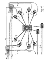
- FIG. 1 A typical prior arrangement of a subsea production system 5 with a cluster of subsea wells 10 is illustrated in Figure 1.
- a number of subsea wells are drilled in a cluster around a central subsea gathering manifold 12.
- Well jumper piping 11 couple the wells 10 to the subsea manifold 12.
- Subsea christmas trees installed on the wells control the flow of oil and/or gas from the wells. Production from each subsea tree is routed into the manifold 12 via jumper piping 11, and then it is transported back to shore via export pipelines 14 laid on the seabed.
- Hydraulically actuated valves and chokes mounted on the subsea trees, and actuated valves mounted on the manifold 12, provide an arrangement to regulate and control the flow of produced fluids. Hydraulic fluids for operating the valves and chokes are delivered to the subsea production system via one or more main hydraulic supply umbilicals 16 laid on the seabed, as shown in Figure 1. Distribution umbilicals 18 deliver fluids from the main umbilicals 16 to the individual subsea trees of wells 10 (and sometimes directly to the manifold 12 as well). Both the main umbilicals 16 and the distribution umbilicals 18 typically consist of several individual hoses or tubes enclosed within a protective sheathing. Umbilicals containing a dozen or more tubes are not uncommon.
- the umbilicals may also deliver corrosion inhibitors, hydrate suppression chemicals, and/or other service fluids to the subsea system.
- one or more tubes in the umbilical serve as vent lines for bleeding annulus pressure from the well casing and/or for depressurizing the manifold 12 and flowlines 14 (for hydrate control and/or remediation).
- thermoplastic hose In the past, hydraulic umbilicals servicing subsea production systems have been constructed of thermoplastic hose. While thermoplastic hose was adequate for subsea applications in shallow to medium depth waters, it is not suitable for use in deep water where ambient hydrostatic pressure can be several thousand pounds per square inch. Some of the fluids contained within the umbilical tubes are significantly less dense than seawater, for example: methanol used for hydrate inhibition. In deep water the tubes containing low density fluids are subjected to a significant external pressure differential. Thermoplastic hose has limited resistance to collapse and is therefore unsuitable for such applications. Umbilical tubes used as "vent" lines may also be subjected to high external collapse pressure during venting operations when internal pressure falls well below seawater ambient pressure.
- thermoplastic hoses are clearly not suitable for such venting operations, due to the collapse problem mentioned above.
- metallic tubes or metal reinforced hoses are replacing thermoplastic hoses in umbilicals serving subsea production systems in deep and ultradeep waters.
- thermoplastic hose umbilicals Although the new metallic tube umbilicals provide excellent collapse resistance, they could pose a serious threat to a subsea system unless adequate snag load protection is incorporated into the system design. With thermoplastic hose umbilicals, snag loads are a lesser concern because such hoses have relatively low tensile strengths. If a subsea umbilical were to be snagged, the thermoplastic hoses typically break away without damaging the attached subsea equipment. This is not the case for umbilicals constructed of metallic tubes, or metal reinforced hoses, because each tube has a tensile strength in the range of 1471 kPa (15 kip) or more.
- the high ductility and elongation of the metal tubing usually results in several tubes being loaded before the first tube has parted.
- several tubes may be transmitting load to the subsea equipment during the progressive break away, increasing the total snag load acting on the subsea equipment.
- thermoplastic hose umbilicals have been equipped with Guillotine type cutter devices which are designed to shear the entire umbilical assembly in the event of a snag.
- One typical guillotine-type umbilical shearing device is commercially available from Oceaneering Company of Tomball, Texas.
- the Oceaneering guillotine style "weaklink" is normally installed on the unarmored umbilical jumper between the Umbilical Termination Assembly (UTA) and the Subsea Installation.
- the jumper is installed through the guillotine perpendicular to the jumper axis. Tensile loads are reacted through a chain assembly (shorter than the umbilical jumper) attached to the UTA and the subsea installation.
- Another guillotine weaklink device provides a large tapered guillotine blade to shear the multiple tubes spaced in a horizontal pattern through an opening facing the guillotine blade. Both devices use a cable or chain to actuate the guillotine cutter blade to sever the umbilical in the event of a snag. Intentional slack is provided in the umbilical to ensure that the cable or chain will become taut (and thereby actuate the guillotine blade to cut the umbilical) before excessive tensile loads are reacted into the attached subsea equipment. With the prior art Oceaneering, guillotine cutter device, the guillotine blade must shear several tubes within the umbilical simultaneously.
- US-A-4,653,776 describes a safety joint for an umbilical which separates the umbilical and severs internal control hoses when a predetermined tension is exceeded, including the general features of the pre-characterizing part of claim 1 which follows.
- the control hoses are severed by opposing cutting edges on mating slots formed by an inner cutting tube and an outer cutting tube which separate when the safety joint separates.
- the safety joint can be installed at any point along the umbilical without cutting the control hoses during installation.
- a primary object of this invention is to provide an effective and reliable load limiting break away device for a subsea umbilical.
- Another object is to provide a compact, reliable reduced force break away device for a metal tube subsea umbilical system.
- Another object of the invention is to provide a breakaway device which not only limits the maximum snag load transmitted into attached subsea equipment, but also allows pre-selection of the order in which individual tubes of the umbilical are severed, thereby ensuring a more controlled break away function; for example with hydraulic lines powering fail-closed valves on subsea trees and manifold being severed first for enabling such valves to close (thereby shutting in the subsea wells) prior to severing lines which are (or could be) exposed to well bore pressure.
- Another object of the invention is to provide a break away device which also incorporates an integral safety device that resists premature actuation and/or tube damage during normal installation operations.
- the object identified above as well as other features and advantages of the invention are incorporated in a break away device which includes inner and outer bodies for severing individual tubes of a subsea umbilical in the event of a snag of the umbilical in accordance with the claims which follow.
- the outer body has a longitudinal cavity through it with upper and lower slots through body walls which are spaced 180° from each other.
- the outer body has a first connection arrangement at a first end.
- the upper slot has a blade secured adjacent to a second end of the outer body which faces inwardly in the slot toward the first end.
- the inner body is positioned for telescopic movement within the cavity of the outer body with a first end of the inner body inserted into the cavity of the outer body with a second end extending outwardly from the second end of the outer body.
- the inner body has a second connection arrangement at the second end.
- the inner body is formed from a solid bar with a plurality of holes, one hole for each of the plurality of umbilical tubes. The holes have their axes aligned with upper and lower slots of the outer body.
- a plurality of individual jumper tubes are connected between first end and second end umbilical termination devices.
- the jumper tubes extend through upper and lower slots of the outer body with only one tube provided for each hole of the inner body.
- a first tension resistant member such as a cable is connected between the first connection arrangement of the outer body and the first umbilical termination device, and a second tension resistant member is connected between the second connection arrangement of the inner body and the second umbilical termination device.
- first and second umbilical termination devices When large opposing forces act on the first and second umbilical termination devices, for example when a main subsea umbilical is snagged on the sea floor by an anchor of a vessel or the like, the inner body is pulled out of the cavity the outer body with the blade in the top slot severing jumper tubes and uncoupling the first and second umbilical termination devices.
- the first and second termination devices may be umbilical termination heads of an "in-line" umbilical on the sea floor.
- the termination devices may be an umbilical termination head connected to a main supply umbilical and an electro-hydraulic distribution module connected to subsea wells.
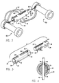
- Figures 2, 3, and 4 illustrate the preferred embodiment of the umbilical break away device 20 of the invention.
- the main elements of the device are an inner body 22 with multiple cross drilled holes 24 and an outer body 32 with slots which define slotted openings at its top and bottom.
- a full length slot 34 is positioned at the bottom of outer body 32.
- Partial longitudinal slots 36, 38 are placed on the top of outer body 32 at 180° from the bottom slot 34.
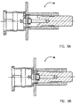
- Outer body 32 is formed from a hollow steel bar with thick walls, for example 1.90 cm to 2.54 cm (3 ⁇ 4" to 1") thick.
- Inner body 22 is formed from a solid round steel bar, for example 6.35 to 7.62 cm (21 ⁇ 2" to 3") diameter.
- a hollow rectangle outer body and a rectangular inner body may alternatively be used.
- the inner body 22 is placed in a telescoping relationship inside the hollow outer body 34 with holes 24 aligned with slots 34 and 38.
- Individual umbilical tubes 40 are passed via bottom slot 34, through the cross drilled holes 24 in the inner body 22, and through the slot 38 in the outer body 32.
- Each of the holes 24 have a diameter which is slightly larger than the outer diameter of a control line tubing 40 that passes through them.
- a downwardly facing shearing blade 39 is secured (as by welding) in the top slot 38 of outer body 32 so as to face control lines extending transversely thereto from holes 24 in inner body 22.
- Stellite weld overlay 31 is provided on shearing blade 39 and about the openings of holes 24 on the top surface of inner body 22.
- Attachment structures are provided at one end 26 of the inner body 22 and at an opposite end 35 of the outer body 32, for attachment of actuation cables which are appropriately anchored to adjacent subsea equipment as described below.
- actuation cables 60, 62 are anchored to the multiple quick connect (MQC) couplers 50, 52 which connect opposite ends of umbilical jumper control lines 40 of the Umbilical Termination Assembly.
- MQC multiple quick connect
- the outer body 32 of the break away device 20 slides, in a telescoping manner, relative to the inner body 22.
- the cutting surface of shearing blade 39 at one end of the upper slot 38 in the outer body 32 sequentially shears individual umbilical tubes 40 passing through the cross drilled holes 24 in the inner body 22. Because a true shearing action is used, the force required to cut an individual tube 40 is reduced by 40-50 percent compared to that required to fail the tube in pure tension.
- the slot 34 in the bottom of the outer body 32 extends across the full length of the outer body 32 such that the tubing is cut in a "single shear" mode, rather than "double shear", thereby reducing the cutting force required.
- a close sliding fit is provided between the inner body 22 and outer body 32 to ensure a clean shearing action with minimal tendency to extrude tubing material into the gap.
- the shape of the cutting blade 39 surface in the outer body slot 38 is preferably configured as an angular cutting edge, although a square shoulder may alternatively be provided.
- An angular cutting edge with particular arrangements may provide a more efficient cutting action and reduce the tendency for the outer body 32 to lift away from the inner body 22 as the tubing 40 is sheared as compared to an alternative square shoulder design.
- Hardfacing material such as stellite and/or a hard metal weld overlay may be provided to strengthen the cutting surface at the end of the upper slot, as well as on the top surface of the inner body, as shown in Figure 3.
- a small diameter shear pin 61 is installed through aligned holes 21, 30 between the inner and outer bodies 22, 32(see Figures 2 and 3).
- the shear pin 61 is typically sized to fail at a load approximately equal to, or slightly higher than, the shear value of the smallest tube 40 passing through the break away device 20. If an umbilical snag occurs, tension from the snagged umbilical first shears the pin 61, and then sequentially shears the umbilical tubes 40 in a controlled manner, typically one tube at a time.
- the pattern of the cross drilled holes 24 through the inner body 22 are staggered and placed in two rows of holes 24 (e.g., row 24' and row 24"), for a one at a time tube shearing action with alternating shearing of tubes in the rows as they approach blade 39. Notice that smaller and larger diameter holes are provided for larger diameter tubes 40' and smaller diameter tubes 40". Other patterns can also be used to provide a combination of shearing actions. For example, where both large and small tubing sizes are involved, an optimum break away unit design combines staggered holes for multiple shearing of the smaller diameter tubes and in-line holes for individual shearing of the large diameter tubes. The in-line hole pattern provides the smallest possible break away force, because tubes are sheared in line, one after another. In contrast, the staggered design allows all the tubes to be severed with a shorter total stroke length, which may be preferable under certain conditions.
- the break away device 20 can be configured using round bodies, as shown in Figures 5A, 5B, 5C and 5D.
- the break away device 20 can be configured using square or rectangular bodies, as mentioned above.
- the square or rectangular body design is indicated when a staggered hole pattern and multiple tube shearing action is preferred.
- the simpler round body design is indicated where an easily manufactured and cost effective configuration is desired.
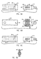
- FIGs 6, 7A and 7B show the preferred embodiment of the Umbilical Termination Assembly Jumper (UTAJ) break away device 20 of the invention incorporated into an Umbilical Termination Assembly (UTA) 17 which connects the main Umbilical Termination Head (UTH) 70 to the Electro-Hydraulic Distribution Module (EHDM) 72. See Figure 1 for placement of the UTA 17 in a subsea system.
- the UTH 70 and the EHDM 72 are mounted on top of the UTA support frame 74, which is mounted to a mud mat assembly 76 to prevent the unit from sinking into the seabed.
- Figure 6 shows these components in exploded and schematic form, while Figure 7 illustrates the actual hardware configurations in side and top views.
- the UTAJ jumper 78 includes a bundle of individual tubes which deliver fluids from the main umbilical 16 to the EHDM 72.
- One end of the UTAJ jumper 78 is attached to the UTH 70 by means of a multiple quick connector (MQC) 50.
- MQC multiple quick connector
- the opposite end of the jumper 78 is attached to the EHDM 72, also using an MQC, referenced here as 52.
- the MQC assemblies 50, 52 contain hydraulic couplers for up to 13 umbilical tubes, and incorporate attachment devices for connecting the actuation cables 60, 62 (See Figure 2) for the progressive tube shearing break away device 20.
- the main umbilical 16 and its end termination (UTH) 70 are mounted on a sliding carriage 80 (the UTH mount frame).
- the entire apparatus is designed and arranged to slide off of the UTA support frame assembly 74 in the event of a snag of umbilical 16.
- Reference number 82 points to an arrow in the direction of travel when UTH assembly 70 is snagged.
- the arrangement is best illustrated in Figures 7A and 7B.
- the UTA 17 is securely mounted onto the UTH mount frame 80, which rides in rails on the UTA support frame 74. If the umbilical were to be snagged, the umbilical 16, the UTH 70, and the UTH mount frame 80 slide in the direction of arrow 82.
- a small retention device typically a shear pin or frangible bolt, secures the UTH mount frame 80 to the UTA support frame 74 and prevents premature movement of the umbilical during normal operations.
- the shear pin or frangible bolt (indicated schematically by line 84 in Figure 6) is typically sized to break at a load equal to, or slightly higher than, the shear value of the smallest tube passing through the break away device.
- one or more ROV releasable latch pins 86 are used to structurally connect the sliding components 80 to the stationary components 74 of the Umbilical Termination Assembly 17.
- the releasable latch pins 86 prevent premature actuation of the break away device 20 during installation (and provides for possible recovery) of the umbilical 16 and its termination hardware.
- the latch 86 is a large structural retaining pin which is designed and arranged for actuation by an ROV (remotely operated vehicle) using the same torque tool which operates the MQC end connector 50 on the umbilical jumper assembly.
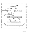
- Figures 8 and 9 illustrate the design of the ROV releasable latch pins 86 and their location within the UTA assembly.
- the latch assemblies are located on the UTA support frame 74, positioned such that they align with the mating hole 87 in the UTH mount frame 80 (see Figure 6).
- the latch pins 86 Prior to installation of the umbilical 16 and the UTA 17, the latch pins 86 are rotated into their extended position, as shown in Figure 9A, such that the large diameter "nose” of the pins engage the holes 87 in the UTH mount frame 80.
- the pins are designed and arranged to withstand the very large umbilical tensile loads (several tons) which are experienced during umbilical installation and recovery. These pins 86 rigidly secure the main umbilical 16 and UTH 70 to the UTA foundation structure 74 during installation to ensure that the break away device 20 is not accidentally actuated.
- an ROV retracts the large latch pin 86 (as illustrated in Figure 9B) prior to first operation of the subsea production system. With the latch pin 86 retracted, the break away device 20 is enabled to protect the subsea system from an umbilical snag.
- the UTH 70 and its mount frame 80 slide off of the UTA support frame74 once the load exceeds that required to break the small retention bolt 84. Thereafter, further movement of the umbilical 16 and UTH 70 cause the UTAJ jumper assembly 78 to elongate. As this occurs, the actuation cables 60, 62 (see Figure 2), attached to the inner 22 and outer 32 bodies of the break away device 20 become taut. When the load in the actuation cables reaches a sufficient level, the shear pin 61 within the break away device is severed. Thereafter, the individual tubes 40, etc., in the UTAJ jumper assembly 78 are sheared in a predictable and controlled manner, thereby protecting the subsea equipment from damage and allowing the subsea valves to close in the wells.
- two break away devices 20 may be configured to actuate simultaneously (when small tubing sizes and shear forces allow).
- the break away devices 20 can be arranged and designed to be actuated sequentially (using staggered lengths of actuation cables) to minimize break away loads when large tubing sizes and shear forces must be accommodated.
- the order of tube failure during a snag event is important. It is desirable for the tubes supplying hydraulic control fluids to the subsea equipment to fail first. In this manner, the fail-safe valves on the subsea trees and/or manifold move to their "safe" position immediately upon loss of hydraulic pressure from the severed umbilical tube(s). Certain other umbilical tubes, such as chemical injection lines and/or vent lines, should be severed last to minimize the potential for backflow of well fluids into the environment. This approach also helps minimize seawater ingress into the wells or manifold system. Accordingly, tubes 40 supplying hydraulic control fluids should be positioned nearest blade 39 while chemical injection lines and/or vent lines should be positioned farthest from blade 39.
- the progressive tube shearing type break away device 20 of this invention allows the user to predetermine the exact order of tube failure during a snag event by placing specific tubes into the appropriate cross drilled holes in the inner body.
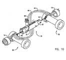
- the break away device 20 of the invention may be incorporated into the umbilical termination assembly (UTA) as described above, or, it may be installed directly into the umbilical itself, as a mid-line installation as illustrated in Figure 10.
- a large ROV removable latch pin 86' is used to secure the inner 22 and outer 32 bodies of the break away device 20 against premature actuation during installation of the umbilical.
- the pin 86' (constructed as illustrated in Figures 9A, 9B) is retracted by an ROV to "arm" or enable the break away device prior to placing the subsea system into operation.
- a small diameter shear pin between the inner and outer bodies prevents premature actuation of the mid-line break away device and/or accidental tube damage during normal operations.
- the progressive tube shearing type break away device 20 of the invention can also be used to provide snag load protection for any large diameter or armored subsea electrical cables serving the subsea production system.
- the electrical cables and their associated armor have significant tensile strength and therefore create a potential snag load hazard for the subsea equipment to which they are attached.
- These electrical cables are sometimes integrated into the main umbilical, along with the hydraulic and chemical injection tubes, or they may be laid as a completely separate electrical umbilical. In either event, the progressive shearing type break away device of the invention may be easily adapted for use on the electrical cables to provide reliable snag load protection for the attached subsea equipment.
Claims (13)
- Agencement de rupture (20) limitant une charge pour un tube ombilical sous-marin, qui comporte une pluralité de tubes individuels (40) comprenant :caractérisé en ce queun corps extérieur (32) ayant une cavité longitudinale, ledit corps extérieur présentant une fente supérieure (38) à travers les parois de corps de ladite cavité, ledit corps extérieur ayant un premier agencement de connexion à une première extrémité, ladite fente supérieure dudit corps extérieur présentant une lame (39) fixée adjacente à une seconde extrémité du corps extérieur qui est située en regard intérieurement dans ladite fente vers ladite première extrémité;un corps intérieur (22) positionné dans ladite cavité du corps extérieur pour un mouvement télescopique, ledit corps intérieur ayant une première extrémité insérée dans ladite cavité dudit corps extérieur avec une seconde extrémité s'étendant extérieurement depuis ladite seconde extrémité dudit corps extérieur, ledit corps intérieur (22) présentant un second agencement de connexion à ladite seconde extrémité,une pluralité de tubes de jonction individuels (40) connectés entre la première extrémité et des seconds dispositifs de terminaison ombilicaux (50, 52) et s'étendant à travers ladite fente supérieure (38) dudit corps extérieur, etun premier organe (60) résistant à la traction, connecté entre ledit premier agencement de connexion du corps extérieur et ledit premier dispositif de terminaison ombilical (50) et un second organe (62) résistant à la traction, connecté entre ledit second agencement de connexion dudit corps intérieur et ledit second dispositif de terminaison ombilical (52),de sorte que de grandes forces opposées sur lesdits premier et second dispositifs de terminaison ombilicaux (50, 52) provoquent l'extraction dudit corps intérieur hors de ladite cavité dudit corps extérieur avec le sectionnement des tubes de jonction (40) par ladite lame (39) et le désaccouplement des premier et second dispositifs de terminaison ombilicaux,
ledit corps intérieur est formé d'une barre solide avec une pluralité de trous (24) à raison d'un trou pour chacun de ladite pluralité de tubes individuels (40), lesdits trous ayant leurs axes alignés avec des fentes supérieure et inférieure (38, 34) dudit corps extérieur qui sont espacées l'une de l'autre de 180°, et en ce que lesdits tubes de jonction s'étendent à travers lesdites fentes supérieure et inférieure (38, 34) dudit corps extérieur à travers l'un desdits trous (24) du corps intérieur. - Agencement selon la revendication 1 dans lequel
lesdits premier et second dispositifs de terminaison (50, 52) sont des têtes de terminaison ombilicales d'un tube ombilical sur le fond de la mer. - Agencement selon la revendication 1 dans lequel
ledit premier dispositif de terminaison (50) est une tête de terminaison ombilicale connectée à un tube ombilical d'alimentation principal,
ladite seconde tête de terminaison ombilicale (70) est disposée et réalisée pour se séparer dudit module de distribution électro- hydraulique quand une force provenant d'un obstacle est appliquée au tube ombilical principal. - Agencement selon la revendication 1 dans lequel
ladite pluralité de trous (24) sont positionnés le long d'une seule ligne longitudinale dudit corps intérieur (22). - Agencement selon la revendication 1 dans lequel
ladite pluralité de trous (24) sont positionnés le long de deux lignes parallèles longitudinales du corps intérieur (22). - Agencement selon la revendication 5 dans lequel
lesdits trous (24) desdites deux lignes longitudinales parallèles sont décalés les uns des autres en fonction de la longueur longitudinale le long des deux lignes, de sorte que lorsque ledit corps intérieur (22) est tiré dudit corps extérieur (32), un tube d'une ligne est d'abord sectionné, puis un tube de l'autre ligne est ensuite sectionné et ainsi de suite jusqu'à ce que tous les tubes aient été sectionnés et que le corps intérieur se sépare du corps extérieur. - Agencement selon la revendication 1 dans lequel
lesdits corps intérieur et extérieur (22, 32) sont de section transversale circulaire. - Agencement selon la revendication 1 dans lequel
lesdits corps intérieur et extérieur (22, 32) sont de section transversale rectangulaire. - Agencement selon la revendication 1 dans lequel
ladite lame (39) présente une face de coupe qui est inclinée par rapport à un axe transversal dudit corps extérieur (32). - Agencement selon la revendication 1 dans lequel
un matériau de surface dur recouvre ladite lame (39) et une surface de
sommet dudit corps intérieur (22) autour d'orifices desdits tubes. - Agencement selon la revendication 1 comprenant de plus,
une goupille de cisaillement (61) placée dans des trous alignés (21, 30) desdits corps intérieur et extérieur (22, 32) quand ledit corps intérieur est placé dans ledit corps extérieur, et ladite goupille de cisaillement est disposée et réalisée pour se rompre là où des forces prédéterminées agissent sur ladite première extrémité dudit corps extérieur et sur ladite seconde extrémité dudit corps intérieur. - Agencement selon la revendication 3 dans lequel
ladite tête de terminaison ombilicale (70) et ledit module de distribution électro- hydraulique sont montés sur un cadre de support (74), et
ladite tête de terminaison ombilicale est fixée de manière amovible audit cadre par une goupille commandée par ROV. - Agencement selon la revendication 12 comprenant en outre
une petite attache (84) de rétention placée entre ladite tête de terminaison ombilicale (70) et ledit cadre de support (74), dans lequel ladite attache est disposée et réalisée pour se rompre quand une force prédéterminée agit sur ladite tête de terminaison ombilicale pour déplacer ladite tête de terminaison ombilicale à partir dudit cadre de support.
Applications Claiming Priority (3)
| Application Number | Priority Date | Filing Date | Title |
|---|---|---|---|
| US10686198P | 1998-11-03 | 1998-11-03 | |
| US106861P | 1998-11-03 | ||
| PCT/US1999/025822 WO2000026496A1 (fr) | 1998-11-03 | 1999-11-03 | Agencement de cisaillement pour tubes ombilicaux sous-marins |
Publications (3)
| Publication Number | Publication Date |
|---|---|
| EP1129271A1 EP1129271A1 (fr) | 2001-09-05 |
| EP1129271A4 EP1129271A4 (fr) | 2002-01-09 |
| EP1129271B1 true EP1129271B1 (fr) | 2003-03-12 |
Family
ID=22313653
Family Applications (1)
| Application Number | Title | Priority Date | Filing Date |
|---|---|---|---|
| EP99956870A Expired - Lifetime EP1129271B1 (fr) | 1998-11-03 | 1999-11-03 | Agencement de cisaillement pour tubes ombilicaux sous-marins |
Country Status (6)
| Country | Link |
|---|---|
| US (1) | US6397948B1 (fr) |
| EP (1) | EP1129271B1 (fr) |
| AU (1) | AU1338900A (fr) |
| BR (1) | BR9914477A (fr) |
| NO (1) | NO20012149L (fr) |
| WO (1) | WO2000026496A1 (fr) |
Cited By (1)
| Publication number | Priority date | Publication date | Assignee | Title |
|---|---|---|---|---|
| NO20141245A1 (no) * | 2014-10-17 | 2016-04-18 | Aker Solutions As | Svakt-ledds arrangement konstruert for plassering i en umbilikal |
Families Citing this family (27)
| Publication number | Priority date | Publication date | Assignee | Title |
|---|---|---|---|---|
| GB9919024D0 (en) * | 1999-08-13 | 1999-10-13 | Coflexip | Methods and apparatus for the emergency actuation of control systems |
| US6789627B2 (en) * | 2000-05-15 | 2004-09-14 | Schlumberger Technology Corporation | Control line cutting tool and method |
| US6526858B1 (en) * | 2000-10-20 | 2003-03-04 | Corning Cable Systems Llc | Cable breakaway assembly |
| US6928765B2 (en) * | 2002-05-03 | 2005-08-16 | Blue Water Concepts, Inc. | Tension activated, hydraulically controlled rope severing device |
| US6880640B2 (en) * | 2002-07-29 | 2005-04-19 | Offshore Systems Inc. | Steel tube flying lead jumper connector |
| CA2563738C (fr) | 2004-05-03 | 2013-02-19 | Exxonmobil Upstream Research Company | Systeme et batiment permettant de supporter des champs marins |
| US7721807B2 (en) * | 2004-09-13 | 2010-05-25 | Exxonmobil Upstream Research Company | Method for managing hydrates in subsea production line |
| US20060201679A1 (en) * | 2005-03-09 | 2006-09-14 | Williams Michael R | Support member for subsea jumper installation, and methods of using same |
| GB0615884D0 (en) * | 2006-08-10 | 2006-09-20 | Subsea 7 Ltd | Method and frame |
| US7631608B1 (en) | 2006-08-25 | 2009-12-15 | The United States Of America As Represented By The Secretary Of The Navy | Underwater cable cutter apparatus |
| US9299480B2 (en) * | 2007-11-13 | 2016-03-29 | Chevron U.S.A. Inc. | Subsea power umbilical |
| NO329101B1 (no) * | 2008-05-20 | 2010-08-23 | Framo Eng As | Arrangement for styring av en fluidstrom |
| US8141909B2 (en) * | 2008-08-12 | 2012-03-27 | Aker Subsea Inc. | Umbilical field connect |
| US8028466B1 (en) * | 2009-04-21 | 2011-10-04 | Schrock Edwin B | Thwartable bottom link for vertical line |
| EP2690249B1 (fr) * | 2012-07-25 | 2015-03-11 | Vetco Gray Controls Limited | Systèmes de commande d'intervention / de reconditionnement |
| US9624745B2 (en) | 2013-06-28 | 2017-04-18 | Oil Tools Of Norway | Downhole umbilical release assembly |
| GB2515575B (en) * | 2013-06-28 | 2016-08-10 | Oil Tools Of Norway As | Downhole umbilical release assembly |
| GB201414733D0 (en) * | 2014-08-19 | 2014-10-01 | Statoil Petroleum As | Wellhead assembly |
| GB2540617A (en) * | 2015-07-24 | 2017-01-25 | Ge Oil & Gas Uk Ltd | Sacrificial breakaway mechanism |
| NO341495B1 (en) | 2016-07-22 | 2017-11-27 | Kvaerner As | An arrangement of an unmanned and remotely operated production facility |
| GB2553354B (en) * | 2016-09-05 | 2019-09-18 | Equinor Energy As | Laying method for pair of mechanically coupled umbilical terminations |
| US10577884B2 (en) | 2017-03-31 | 2020-03-03 | General Electric Company | Blowout prevention system including blind shear ram |
| NO344304B1 (en) * | 2017-12-12 | 2019-10-28 | Fmc Kongsberg Subsea As | Subsea actuator for actuating a subsea rotating component, as well as a method of operating an actuator |
| US20190301260A1 (en) | 2018-03-28 | 2019-10-03 | Fhe Usa Llc | Remotely operated fluid connection |
| US11959358B2 (en) * | 2019-06-10 | 2024-04-16 | Downing Wellhead Equipment, Llc | Bleeding off a hydraulic fracturing manifold used in oil and gas extraction operations |
| CN112643124B (zh) * | 2020-12-22 | 2022-03-04 | 江苏省镔鑫钢铁集团有限公司 | 一种精轧螺纹钢冷剪剪切装置及剪切工艺 |
| US20220371708A1 (en) * | 2021-05-21 | 2022-11-24 | Systems Analysis & Integration, Inc. | Underwater cutting device |
Family Cites Families (9)
| Publication number | Priority date | Publication date | Assignee | Title |
|---|---|---|---|---|
| US2755550A (en) | 1955-10-07 | 1956-07-24 | Lockheed Aircraft Corp | Reefing line cutter |
| US3633667A (en) * | 1969-12-08 | 1972-01-11 | Deep Oil Technology Inc | Subsea wellhead system |
| US3621744A (en) * | 1970-06-04 | 1971-11-23 | Thiokol Chemical Corp | Cable cutter |
| US3882748A (en) * | 1974-03-25 | 1975-05-13 | Us Navy | Cable cutter assembly |
| EP0146647B1 (fr) * | 1983-12-17 | 1987-11-04 | Leybold Aktiengesellschaft | Méthode de transformation des valeurs mesurées d'un vacuomètre de frottement de gaz et un vacuomètre de frottement de gaz pourvu d'un circuit pour la mise en oeuvre de ce procédé |
| US4653776A (en) * | 1986-03-07 | 1987-03-31 | Multiflex International, Inc. | Umbilical safety joint |
| US4923005A (en) * | 1989-01-05 | 1990-05-08 | Otis Engineering Corporation | System for handling reeled tubing |
| US5177317A (en) | 1992-01-09 | 1993-01-05 | Teledyne Industries, Inc. | Cable cutter assembly |
| US5703315A (en) * | 1996-04-25 | 1997-12-30 | Loral Vought Systems Corporation | Device and method for transversely cutting a band |
-
1999
- 1999-11-03 AU AU13389/00A patent/AU1338900A/en not_active Abandoned
- 1999-11-03 BR BR9914477-8A patent/BR9914477A/pt not_active Application Discontinuation
- 1999-11-03 WO PCT/US1999/025822 patent/WO2000026496A1/fr active IP Right Grant
- 1999-11-03 EP EP99956870A patent/EP1129271B1/fr not_active Expired - Lifetime
- 1999-11-03 US US09/433,413 patent/US6397948B1/en not_active Expired - Fee Related
-
2001
- 2001-04-30 NO NO20012149A patent/NO20012149L/no not_active Application Discontinuation
Cited By (5)
| Publication number | Priority date | Publication date | Assignee | Title |
|---|---|---|---|---|
| NO20141245A1 (no) * | 2014-10-17 | 2016-04-18 | Aker Solutions As | Svakt-ledds arrangement konstruert for plassering i en umbilikal |
| WO2016060571A1 (fr) * | 2014-10-17 | 2016-04-21 | Aker Subsea As | Agencement à liaison faible et procédé comprenant un agencement à liaison faible |
| GB2546675A (en) * | 2014-10-17 | 2017-07-26 | Aker Solutions As | Weak link arrangement and a method comprises a weak link arrangement |
| NO342204B1 (no) * | 2014-10-17 | 2018-04-16 | Aker Solutions As | Svakt-ledds arrangement konstruert for plassering i en umbilikal |
| GB2546675B (en) * | 2014-10-17 | 2021-02-24 | Aker Solutions As | Weak link arrangement and a method comprises a weak link arrangement |
Also Published As
| Publication number | Publication date |
|---|---|
| AU1338900A (en) | 2000-05-22 |
| WO2000026496A1 (fr) | 2000-05-11 |
| US6397948B1 (en) | 2002-06-04 |
| EP1129271A1 (fr) | 2001-09-05 |
| BR9914477A (pt) | 2001-10-30 |
| EP1129271A4 (fr) | 2002-01-09 |
| NO20012149D0 (no) | 2001-04-30 |
| NO20012149L (no) | 2001-04-30 |
Similar Documents
| Publication | Publication Date | Title |
|---|---|---|
| EP1129271B1 (fr) | Agencement de cisaillement pour tubes ombilicaux sous-marins | |
| US20110284237A1 (en) | Drilling riser release method | |
| RU2579062C2 (ru) | Способ и система локализации неуправляемого потока текучих сред коллектора в окружающую среду | |
| EP0709545B1 (fr) | Système de forage à trou mince dans des eaux profondes | |
| US7891429B2 (en) | Riserless modular subsea well intervention, method and apparatus | |
| EP2609284B1 (fr) | Système de sécurisation d'un puits sous-marin | |
| US9353602B2 (en) | Riser weak link | |
| US7487836B2 (en) | Riserless modular subsea well intervention, method and apparatus | |
| CN103154424A (zh) | 海底自由站立式立管系统和方法 | |
| US20120273219A1 (en) | Emergency disconnect system for riserless subsea well intervention system | |
| US20100236786A1 (en) | System and method for performing intervention operations with a subsea y-tool | |
| BR102013009192A2 (pt) | ferramenta de cimentação de espaço anular para operação de abandono de poço submarino | |
| US9260931B2 (en) | Riser breakaway connection and intervention coupling device | |
| US20100307760A1 (en) | Subsea wireline intervention system | |
| MX2013003989A (es) | Montajes submarinos maritimos. | |
| US4653776A (en) | Umbilical safety joint | |
| EP2601375B1 (fr) | Procédé et système permettant d'effectuer des opérations de puits | |
| WO2021110988A1 (fr) | Dispositif de fixation pour lignes sous-marines | |
| US11555358B1 (en) | Method and apparatus for protection of control lines and other equipment | |
| US11028663B1 (en) | Process and apparatus for installing a payload onto a subsea structure | |
| Dines et al. | An operational subsea wireline system | |
| Cobb et al. | A Subsea Wireline Service System | |
| Harris | Floating Drilling Experience in Santa Barbara Channel, California | |
| Society for Underwater Technology (SUT) et al. | Building In Cost Saving-Diver Reconnectable Umbilical Weak Link Protection System | |
| Moreira | The Use of Dynamically Positioned Units in Subsea Completions Offshore Brazil |
Legal Events
| Date | Code | Title | Description |
|---|---|---|---|
| PUAI | Public reference made under article 153(3) epc to a published international application that has entered the european phase |
Free format text: ORIGINAL CODE: 0009012 |
|
| 17P | Request for examination filed |
Effective date: 20010216 |
|
| AK | Designated contracting states |
Kind code of ref document: A1 Designated state(s): AT BE CH CY DE DK ES FI FR GB GR IE IT LI LU MC NL PT SE |
|
| AX | Request for extension of the european patent |
Free format text: AL;LT;LV;MK;RO;SI |
|
| RIN1 | Information on inventor provided before grant (corrected) |
Inventor name: ROGALA, STANLEY, J. Inventor name: JOAN, SYLVESTER, A. Inventor name: WENDT, DAVID, E. Inventor name: ROSS, CHRISTINA, A. Inventor name: JOHANSEN, JOHN, A. Inventor name: WILLIAMS, MICHAEL, R. |
|
| A4 | Supplementary search report drawn up and despatched |
Effective date: 20011127 |
|
| AK | Designated contracting states |
Kind code of ref document: A4 Designated state(s): AT BE CH CY DE DK ES FI FR GB GR IE IT LI LU MC NL PT SE |
|
| RIC1 | Information provided on ipc code assigned before grant |
Free format text: 7E 21B 7/00 A, 7E 21B 29/12 B, 7B 23D 23/00 B |
|
| 17Q | First examination report despatched |
Effective date: 20020410 |
|
| REG | Reference to a national code |
Ref country code: DE Ref legal event code: 8566 |
|
| RAP1 | Party data changed (applicant data changed or rights of an application transferred) |
Owner name: FMC TECHNOLOGIES, INC. |
|
| GRAH | Despatch of communication of intention to grant a patent |
Free format text: ORIGINAL CODE: EPIDOS IGRA |
|
| GRAH | Despatch of communication of intention to grant a patent |
Free format text: ORIGINAL CODE: EPIDOS IGRA |
|
| GRAA | (expected) grant |
Free format text: ORIGINAL CODE: 0009210 |
|
| AK | Designated contracting states |
Designated state(s): GB |
|
| REG | Reference to a national code |
Ref country code: GB Ref legal event code: FG4D |
|
| PLBE | No opposition filed within time limit |
Free format text: ORIGINAL CODE: 0009261 |
|
| STAA | Information on the status of an ep patent application or granted ep patent |
Free format text: STATUS: NO OPPOSITION FILED WITHIN TIME LIMIT |
|
| 26N | No opposition filed |
Effective date: 20031215 |
|
| PGFP | Annual fee paid to national office [announced via postgrant information from national office to epo] |
Ref country code: GB Payment date: 20041004 Year of fee payment: 6 |
|
| PG25 | Lapsed in a contracting state [announced via postgrant information from national office to epo] |
Ref country code: GB Free format text: LAPSE BECAUSE OF NON-PAYMENT OF DUE FEES Effective date: 20051103 |
|
| GBPC | Gb: european patent ceased through non-payment of renewal fee |
Effective date: 20051103 |