EP1128619A2 - Displaying interference-free signals - Google Patents
Displaying interference-free signals Download PDFInfo
- Publication number
- EP1128619A2 EP1128619A2 EP01301520A EP01301520A EP1128619A2 EP 1128619 A2 EP1128619 A2 EP 1128619A2 EP 01301520 A EP01301520 A EP 01301520A EP 01301520 A EP01301520 A EP 01301520A EP 1128619 A2 EP1128619 A2 EP 1128619A2
- Authority
- EP
- European Patent Office
- Prior art keywords
- signal
- producing
- symbol interference
- inter symbol
- isi
- Prior art date
- Legal status (The legal status is an assumption and is not a legal conclusion. Google has not performed a legal analysis and makes no representation as to the accuracy of the status listed.)
- Withdrawn
Links
- 238000005259 measurement Methods 0.000 claims description 20
- 238000001914 filtration Methods 0.000 claims description 9
- 238000000034 method Methods 0.000 claims description 9
- 238000013507 mapping Methods 0.000 claims 3
- 238000001514 detection method Methods 0.000 claims 2
- 230000005540 biological transmission Effects 0.000 description 4
- 230000000694 effects Effects 0.000 description 3
- 238000001228 spectrum Methods 0.000 description 3
- 238000004891 communication Methods 0.000 description 2
- 238000012937 correction Methods 0.000 description 2
- 230000001419 dependent effect Effects 0.000 description 2
- 238000011161 development Methods 0.000 description 2
- 238000010586 diagram Methods 0.000 description 2
- 238000010295 mobile communication Methods 0.000 description 2
- 238000012360 testing method Methods 0.000 description 2
- 238000003745 diagnosis Methods 0.000 description 1
- 238000005516 engineering process Methods 0.000 description 1
- 230000010363 phase shift Effects 0.000 description 1
- 238000007493 shaping process Methods 0.000 description 1
- 230000008054 signal transmission Effects 0.000 description 1
- 238000012795 verification Methods 0.000 description 1
Images





Classifications
-
- H—ELECTRICITY
- H04—ELECTRIC COMMUNICATION TECHNIQUE
- H04L—TRANSMISSION OF DIGITAL INFORMATION, e.g. TELEGRAPHIC COMMUNICATION
- H04L25/00—Baseband systems
- H04L25/02—Details ; arrangements for supplying electrical power along data transmission lines
- H04L25/03—Shaping networks in transmitter or receiver, e.g. adaptive shaping networks
- H04L25/03006—Arrangements for removing intersymbol interference
Definitions
- the present invention relates to displaying signals in the presence of interference and in particular to methods of displaying signal quality in digital data transmission systems in which inter-symbol interference (ISI) is present and cannot be practically removed by passing the signal through a filter. More specifically, the present invention relates to the display of signal quality in PSK transmission systems having ISI, such as GSM-EDGE.
- ISI inter-symbol interference
- PSK Phase Shift Keying
- EMM Error-Vector-Magnitude
- ISI inter-symbol interference
- GSM Global System for Mobile Communications
- GSM-EDGE represents an extension of GSM technology which allows for increased data rates in the same spectrum by changing the modulation from GMS's constant envelope GMSK 8-PSK to a system using 3 ⁇ /8 8-PSK with symbol rotation, using both phase and amplitude modulation, but using the same sets of GSM filters. While GSM-EDGE offers increased data rates, it also suffers from significant in increases inter-symbol interference, as the transmit filter was chosen to produce a spectrum similar to that produced by earlier 0.3 GMSK waveforms, without regard to its ISI properties..
- This inter-symbol interference has the effect of making a raw constellation display very difficult to use as an indicator of signal quality. What is needed is a method of displaying signal quality in systems having inherent inter-symbol interference.
- Signal quality in an input signal containing inter-symbol interference is displayed by modeling the signal as comprising an ideal signal component plus an ISI component plus an error component, and subtracting out the ISI, leaving the ideal signal plus the error.
- the signal component is recovered from the input signal through demodulation.
- the recovered bit sequence is used to generate a correction signal equal but opposite to the ISI.
- the correction signal is added to the input signal in a feedforward fashion, resulting in the input signal minus ISI, plus any residual errors.
- the signal with these residual errors is then displayed.
- the error signal is derived from the input signal, and combined with a regenerated ideal signal, producing the signal with error, without ISI.
- GSM (originally Groupe Spécial Mobile, now known as Global System for Mobile Communications) is a digital communications system in world wide use. GSM uses 0.3 GMSK modulation with transmit filters specified by an international standard to transmit signals including voice and data. These standards include ETSI GSM 05.04, 05.05, 11.10, and 11.21.
- EMM Error-Vector-Magnitude
- ISI inter-symbol interference
- Fig. 2 shows a typical I-Q diagram of a 16-PSK signal without ISI.
- the symbols form a fairly tight constellation in the I-Q space.
- the transmit filter introduces ISI, which the measurement filter cannot remove -- in fact, the measurement filter increases the amount of ISI present.
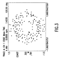
- Fig. 3 shows a 16-PSK signal with ISI present from the transmit filter.
- Fig. 1 shows a block diagram of an EVM instrument as known to the art.
- Input signal 100 passes first to frequency compensation network 110, which corrects the signal for frequency.
- the signal is then passed through measurement filter 120, defined by the particular standard, and then through compensator 130 to adjust phase, amplitude origin offset, and droop.
- the output of compensator 130 is measured signal output 140.
- the signal from frequency compensator 110 is passed to data detector 150, which resolves the signal into bits. These bits are passed to symbol mapper 160, which regenerates ideal symbols from the detected bit stream.
- These ideal symbols are then passed through transmit filter 170 and measurement filter 180, producing signal 190, which is the ideal signal plus the ISI introduced by the transmit and measurement filters.
- transmit filter 170 and measurement filter 180 may be convolved to produce one filter.
- This filtering is commonly implemented using a digital signal processor in a manner known to the art, which produces filters with very close to ideal characteristics.
- Compensation network 110 and compensator 130 are designed as is known in the art to minimize the RMS error present.
- Measured signal 140 may be modeled as an ISI-free signal plus any ISI, plus error.
- Ideal signal 190 may be modeled as the ISI-free signal plus ISI. Subtracting these two signals 200 on a sample by sample basis produces error signal 210, as (ISI-free signal plus ISI plus error) minus (ISI-free signal plus ISI) leaves error.
- Measured signal 140 may be sampled at one sample per symbol (the symbol rate is determined by the particular standard) and displayed to produce the I-Q plot shown as Fig 2.
- measured signal 140 is ISI free in original GSM.
- ISI introduced by the transmit filter is not removed by the measurement or receive filters, and is in fact increased.
- an I-Q display of measured signal 140 for a GSM-EDGE signal produces a plot similar to Fig. 3.
- measured signal 140 may be modeled as the ISI-free signal plus ISI plus error.
- Ideal signal 190 may be modeled as the ISI-free signal plus ISI. The difference 200 between these signals produces error signal 210.
- signal 410 which is the ISI-free signal plus the error, but without ISI present.
- Signal 410 may be sampled at one sample per symbol to produce an ISI free I-Q display.
- many or all of the elements of Fig. 4 may be implemented in one or more digital signal processor chips.
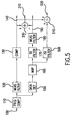
- FIG. 5 A second embodiment of the present invention is shown in Fig. 5. Recall that signal 140 may be modeled as the ISI-free signal plus ISI plus error. The ideal symbols without ISI is also present at the output of symbol mapper 160. These ideal symbols are passed through ISI generating filter 500, producing a signal which consists only of ISI. This filter is produced by taking the negative of the impulse response of the convolution of the transmit and measurement filters, with the center tap set to zero. Preferably implemented using a digital signal processor, ISI generating filter 500 produces a signal containing ISI, but with the center tap set to zero, without the current symbol.
- This ISI signal is then summed 510 with measured signal 140, producing signal 520 which may be modeled as the ISI-free signal plus ISI plus error, minus ISI, which results in the ideal signal plus the error.
- Signal 510 may be sampled at one sample per symbol and displayed on an I-Q plane.
- the elements of this embodiment of the present invention are particularly suitable for implementation using a digital signal processor.
Landscapes
- Engineering & Computer Science (AREA)
- Power Engineering (AREA)
- Computer Networks & Wireless Communication (AREA)
- Signal Processing (AREA)
- Digital Transmission Methods That Use Modulated Carrier Waves (AREA)
- Dc Digital Transmission (AREA)
- Noise Elimination (AREA)
- Detection And Prevention Of Errors In Transmission (AREA)
- Monitoring And Testing Of Transmission In General (AREA)
Abstract
Description
Claims (14)
- In an instrument for displaying an input signal which may contain inter symbol interference, the method of producing a representation of the input signal without inter symbol interference comprising:producing a first measured signal from the input signal,producing a second ISI-free signal from the input signal,producing a third ideal signal with inter symbol interference from the second signal,subtracting the third ideal signal with inter symbol interference from the first measured signal producing a fourth error signal,and adding the fourth error signal to the second ISI-free signal producing a representation of the input signal without inter symbol interference.
- In an instrument for displaying an input signal which may contain inter symbol interference, the method of producing a representation of the input signal without inter symbol interference comprising:producing a first measured signal from the input signal,producing a second ISI-free signal from the input signal,producing a third ideal signal with inter symbol interference from the second signal,subtracting the third ideal signal with inter symbol interference from the first measured signal producing a fourth error signal,producing a fifth signal consisting of inter symbol interference from the second ideal signal, andsubtracting the fifth signal consisting of inter symbol interference from the first measured signal, producing a representation of the input signal without inter symbol interference.
- The method of Claim 1 or 2, where the step of producing the first measured signal further comprises:frequency compensating the input signal,filtering the compensated input signal by a measurement filter, andcompensating the filtered signal to produce the first measured signal.
- The method of any preceding claim where the step of producing the second ISI-free signal comprises:detecting a series of bits from the input signal, andmapping the detected series of bits onto a series of symbols.
- The method of any preceding claim where the step of producing the third ideal signal with inter symbol interference from the second ISI-free signal comprises:filtering the second ISI-free signal by a transmit filter, andfurther filtering the resulting signal by a measurement filter.
- The method of any of claims 1 to 4, where the step of producing the third ideal signal with inter symbol interference from the second ISI-free signal comprises filtering the second ideal signal with a filter which is the convolution of a transmit filter and a measurement filter.
- The method of claim 2 where the step of producing the fifth signal consisting of only inter symbol interference from the second ideal signal comprises filtering the second ideal signal by a filter which is the impulse response of the convolution of the transmit and measurement filters with the center tap set to zero.
- In an instrument for displaying an input signal which may contain inter symbol interference, apparatus for producing a representation of the input signal without inter symbol interference, comprising:first signal processing means for producing a measured signal from the input signal,second signal processing means for producing an ISI-free signal from the input signal,third signal processing means for producing an ideal signal with inter symbol interference from the output of the second signal processing means,means for subtracting the ideal signal with inter symbol interference from the measured signal, producing an error signal, andsumming means for summing the error signal with the ideal signal, producing a representation of the input signal without inter symbol interference.
- In an instrument for displaying an input signal which may contain inter symbol interference, apparatus for producing a representation of the input signal without inter symbol interference, comprising:first signal processing means for producing a measured signal from the input signal,second signal processing means for producing an ISI-free signal from the input signal,third signal processing means for producing an ideal signal with inter symbol interference from the output of the second signal processing means,means for subtracting the ideal signal with inter symbol interference from the measured signal, producing an error signal,fourth signal processing means for producing a signal consisting of inter symbol interference from the ISI-free signal, andsubtracting means for subtracting the inter symbol interference signal from the measured signal, producing a representation of the input signal without inter symbol interference.
- The apparatus of claim 8 or 9 where the first signal processing means further comprises:frequency compensation means connected to the input signal,measurement filter means connected to the frequency compensation means, andcompensation means connected to the measurement filter means, producing the measured signal.
- The apparatus of any of claims 8 to 10, where the second signal processing means further comprises:data detection means for detecting a series of symbols from the input signal, andsymbol mapping means for mapping the series of bits from the data detection means onto an ideal series of symbols.
- The apparatus of any of claims 8 to 11 where the third signal processing means further comprises:transmit filter means for filtering the ideal signal, andmeasurement filter means for filtering the output of the transmit filter.
- The apparatus of any of claims 8 to 11, where the third signal processing means further comprises filter means which is the convolution of the transmit filter and the measurement filter.
- The apparatus of claim 9 where the fourth signal processing means comprises filtering means which is the impulse response of the convolution of the transmit and measurement filters with the center tap set to zero.
Applications Claiming Priority (2)
| Application Number | Priority Date | Filing Date | Title |
|---|---|---|---|
| US09/510,490 US6597751B1 (en) | 2000-02-23 | 2000-02-23 | Method of displaying signals in the presence of inter symbol interference |
| US510490 | 2000-02-23 |
Publications (2)
| Publication Number | Publication Date |
|---|---|
| EP1128619A2 true EP1128619A2 (en) | 2001-08-29 |
| EP1128619A3 EP1128619A3 (en) | 2003-01-02 |
Family
ID=24030953
Family Applications (1)
| Application Number | Title | Priority Date | Filing Date |
|---|---|---|---|
| EP01301520A Withdrawn EP1128619A3 (en) | 2000-02-23 | 2001-02-21 | Displaying interference-free signals |
Country Status (4)
| Country | Link |
|---|---|
| US (1) | US6597751B1 (en) |
| EP (1) | EP1128619A3 (en) |
| JP (1) | JP2001285214A (en) |
| CN (1) | CN1245821C (en) |
Families Citing this family (4)
| Publication number | Priority date | Publication date | Assignee | Title |
|---|---|---|---|---|
| US7020070B2 (en) * | 2001-04-10 | 2006-03-28 | Telefonaktiebolaget L M Ericsson (Publ) | Selectively controlled modulation distortion of an IQ-baseband signal |
| TWI235560B (en) * | 2003-10-31 | 2005-07-01 | Ind Tech Res Inst | Apparatus and method for synchronization of OFDM systems |
| US7375741B2 (en) * | 2005-03-24 | 2008-05-20 | Himax Technologies Limited | Circuit and method for eliminating image interfering with desired channel |
| US9654327B2 (en) * | 2015-05-27 | 2017-05-16 | Xilinx, Inc. | Channel adaptive ADC-based receiver |
Family Cites Families (4)
| Publication number | Priority date | Publication date | Assignee | Title |
|---|---|---|---|---|
| US3621139A (en) * | 1970-05-11 | 1971-11-16 | North American Rockwell | Data receiver with intersymbol interference correction |
| US5408503A (en) * | 1992-07-03 | 1995-04-18 | U.S. Philips Corporation | Adaptive viterbi detector |
| US5606464A (en) * | 1995-01-31 | 1997-02-25 | Lucent Technologies Inc. | Cancellation of precursor intersymbol interference in magnetic recording channels |
| CA2220740C (en) * | 1996-11-12 | 2002-03-19 | Samsung Electronics Co., Ltd. | Symbol decoding apparatus with plural data slicers and an adaptive ntsc co-channel interference filter |
-
2000
- 2000-02-23 US US09/510,490 patent/US6597751B1/en not_active Expired - Fee Related
- 2000-12-25 CN CNB001364618A patent/CN1245821C/en not_active Expired - Fee Related
-
2001
- 2001-02-20 JP JP2001043200A patent/JP2001285214A/en active Pending
- 2001-02-21 EP EP01301520A patent/EP1128619A3/en not_active Withdrawn
Also Published As
| Publication number | Publication date |
|---|---|
| CN1245821C (en) | 2006-03-15 |
| US6597751B1 (en) | 2003-07-22 |
| JP2001285214A (en) | 2001-10-12 |
| EP1128619A3 (en) | 2003-01-02 |
| CN1310538A (en) | 2001-08-29 |
Similar Documents
| Publication | Publication Date | Title |
|---|---|---|
| US6246717B1 (en) | Measurement test set and method for in-service measurements of phase noise | |
| AU764818B2 (en) | Signaling using phase rotation techniques in a digital communications system | |
| EP1601129B1 (en) | Method of determining true error vector magnitude in a wireless lan | |
| US6275523B1 (en) | In-service measurement of transmitter nonlinearities | |
| MXPA01013125A (en) | Method for estimating signal-to-noise ratio of digital carriers in an am compatible digital audio broadcasting system. | |
| CN103248593A (en) | Method and system for frequency offset estimation and elimination | |
| US6389572B1 (en) | Method of extracting bits from modulated waveforms | |
| US6373903B1 (en) | Apparatus and method for increasing the effective data rate in communication systems utilizing phase modulation | |
| US6597751B1 (en) | Method of displaying signals in the presence of inter symbol interference | |
| EP1013040A1 (en) | Data transmission method and radio system | |
| CN117834034B (en) | Self-adaptive modulation and demodulation method for 100g industrial grade single-wave optical module | |
| EP1130866B1 (en) | Correction of quadrature and gain errors in homodyne receivers | |
| KR19990082417A (en) | Coherent modulation of the CPM signal | |
| EP1758282A1 (en) | Test apparatus | |
| US7729441B2 (en) | Method and system for data transmission with decreased bit error rate | |
| US7831224B2 (en) | Radio-frequency IC for a mobile radio transmitter | |
| US7366233B1 (en) | Assembly for measurement demodulation and modulation error detection of a digitally modulated receive signal | |
| EP3014776B1 (en) | Systems and methods for equalization in radio frequency signal paths | |
| US20080031377A1 (en) | Method and system for data transmission with decreased bit error rate | |
| US8223907B2 (en) | Method for deriving parasitic signals from modulated digital signals | |
| JPH09261285A (en) | Multilevel VSB demodulator | |
| US8594165B2 (en) | Half-symbol constellation display | |
| Pascual Iserte et al. | Lab Sessions | |
| JP3601646B2 (en) | Band edge equalization method and apparatus | |
| Nilsson et al. | Live Demonstration of Mismatch Compensation for Time-Interleaved ADCs |
Legal Events
| Date | Code | Title | Description |
|---|---|---|---|
| PUAI | Public reference made under article 153(3) epc to a published international application that has entered the european phase |
Free format text: ORIGINAL CODE: 0009012 |
|
| AK | Designated contracting states |
Kind code of ref document: A2 Designated state(s): AT BE CH CY DE DK ES FI FR GB GR IE IT LI LU MC NL PT SE TR |
|
| AX | Request for extension of the european patent |
Free format text: AL;LT;LV;MK;RO;SI |
|
| RAP1 | Party data changed (applicant data changed or rights of an application transferred) |
Owner name: AGILENT TECHNOLOGIES, INC. (A DELAWARE CORPORATION |
|
| PUAL | Search report despatched |
Free format text: ORIGINAL CODE: 0009013 |
|
| AK | Designated contracting states |
Kind code of ref document: A3 Designated state(s): AT BE CH CY DE DK ES FI FR GB GR IE IT LI LU MC NL PT SE TR |
|
| AX | Request for extension of the european patent |
Free format text: AL;LT;LV;MK;RO;SI |
|
| 17P | Request for examination filed |
Effective date: 20030610 |
|
| AKX | Designation fees paid |
Designated state(s): DE FR GB |
|
| RAP1 | Party data changed (applicant data changed or rights of an application transferred) |
Owner name: AGILENT TECHNOLOGIES, INC. |
|
| GRAP | Despatch of communication of intention to grant a patent |
Free format text: ORIGINAL CODE: EPIDOSNIGR1 |
|
| STAA | Information on the status of an ep patent application or granted ep patent |
Free format text: STATUS: THE APPLICATION IS DEEMED TO BE WITHDRAWN |
|
| 18D | Application deemed to be withdrawn |
Effective date: 20080408 |