EP1128616A2 - Communication system, communication device and communication method - Google Patents
Communication system, communication device and communication method Download PDFInfo
- Publication number
- EP1128616A2 EP1128616A2 EP01301549A EP01301549A EP1128616A2 EP 1128616 A2 EP1128616 A2 EP 1128616A2 EP 01301549 A EP01301549 A EP 01301549A EP 01301549 A EP01301549 A EP 01301549A EP 1128616 A2 EP1128616 A2 EP 1128616A2
- Authority
- EP
- European Patent Office
- Prior art keywords
- packet
- communication device
- status
- transmitting
- receiving
- Prior art date
- Legal status (The legal status is an assumption and is not a legal conclusion. Google has not performed a legal analysis and makes no representation as to the accuracy of the status listed.)
- Withdrawn
Links
Images














Classifications
-
- H—ELECTRICITY
- H04—ELECTRIC COMMUNICATION TECHNIQUE
- H04L—TRANSMISSION OF DIGITAL INFORMATION, e.g. TELEGRAPHIC COMMUNICATION
- H04L12/00—Data switching networks
- H04L12/28—Data switching networks characterised by path configuration, e.g. LAN [Local Area Networks] or WAN [Wide Area Networks]
- H04L12/40—Bus networks
-
- H—ELECTRICITY
- H04—ELECTRIC COMMUNICATION TECHNIQUE
- H04L—TRANSMISSION OF DIGITAL INFORMATION, e.g. TELEGRAPHIC COMMUNICATION
- H04L12/00—Data switching networks
- H04L12/28—Data switching networks characterised by path configuration, e.g. LAN [Local Area Networks] or WAN [Wide Area Networks]
- H04L12/40—Bus networks
- H04L12/40052—High-speed IEEE 1394 serial bus
- H04L12/40058—Isochronous transmission
-
- H—ELECTRICITY
- H04—ELECTRIC COMMUNICATION TECHNIQUE
- H04L—TRANSMISSION OF DIGITAL INFORMATION, e.g. TELEGRAPHIC COMMUNICATION
- H04L12/00—Data switching networks
- H04L12/64—Hybrid switching systems
- H04L12/6418—Hybrid transport
Definitions
- This invention relates to a communication system, a communication device and a communication method to be used for transmission of data among a plurality of devices connected to a serial bus.
- magneto-optical disc devices adapted to recording data to and reproducing data from a magneto-optical disc such as an MD and optical disc devices adapted to reproducing signals from an optical disc such as a CD and provided with an interface for exchanging data with a serial bus according to a predetermined protocol are known.
- Such devices that are provided with an interface to be connected to a serial bus can transmit data as a stream to any desired device that is connected to the network comprising the serial bus.
- a device trying to exchange data streams operates as controller that controls the partner device as target.
- the controller has to bear a heavy load of checking and managing all the conditions for exchanging data streams.
- a communication system comprising:
- a communication system comprising:
- a communication device comprising:
- a communication device comprising:
- a communication method comprising: a first step of transmitting data to a data transmission bus as a periodical packet; and a second step of monitoring the periodical packet being transmitted in said first step and starting to receive the packet upon detecting the transmission of the packet as a packet available to it.
- a communication method comprising:
- a communication system comprising:
- a communication device comprising:
- a communication device comprising:
- a communication method comprising:
- a communication method comprising:
- processing operations can be conducted in a distributed fashion as the devices operate in a concerted manner so that it is no longer necessary for a single controller to control all the devices and all the processing operations. For example, if a plurality of streams are running on the bus, each device trying to catch a stream can determine the stream it actually catches.
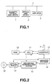
- FIG. 1 is a schematic block diagram of the first embodiment of communication system according to the invention and including a recording/reproduction device comprising a magneto-optical disc device 1 for recording data on and reproducing data from a magneto-optical disc such as an main body, an optical disc device 2 for reproducing data from an optical disc such as CD and an amplifier 3 for outputting sound.
- a recording/reproduction device comprising a magneto-optical disc device 1 for recording data on and reproducing data from a magneto-optical disc such as an main body, an optical disc device 2 for reproducing data from an optical disc such as CD and an amplifier 3 for outputting sound.
- the magneto-optical disc device 1 and the optical disc device 2 are referred to as the first devices adapted to transmit data as packets, whereas the amplifier is referred to as the second device adapted to receive packets.
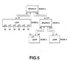
- the CPU 11 sends a control instruction to the serial bus 4 by way of the interface 10.
- the IEEE1394 Standards specifying a serial bus 4 to be used for a recording/reproduction device is based on the CSR (control & status register) architecture having an address space of 64 bits as defined in ISO/IEC13213.
- FIG. 4 is a schematic illustration of the structure of the address space of the CSR architecture.
- the 16 bits of the higher orders represent the node ID of the node on each IEEE1394 bus and the remaining 48 bits are used to define the address space given to each node.
- the higher order 16 bits are further divided into 10 bits representing the bus ID and 6 bits representing the physical ID (node ID in a rigorous sense of the word).
- 1023 buses and 63 nodes because the value expressed by 1s for all the bits is used for a special purpose.
- a tree recognition process is brought in and the entire topology of the network is transformed into a single tree in that process.
- one of the node of the tree is specified as root and all the physical connections connected to the root are directed toward the root node.
- the node that secured the bus as a result of a bus arbitration conducted in a time period of each cycle when the bus is not used for isochronous transmission transmits an asynchronous packet.
- an asynchronous transmission while it is guaranteed that data will be transmitted reliably but the timing of transmission will not necessarily be same always.
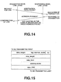
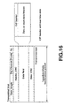
- the CIP header is located at the top of the data field of a synchronous packet and contains information on the type of the real time data contained in the data field that follows it.
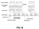
- the protocol is designed to transmit a source packet from an application on a device to the application on another device.
- the source packet of the transmitter side is based on the assumption that it has a fixed length that is determined as a function of the data type.
- the data rate is invariable.
- a time stamp field necessary for restoring the real time data is provided in the CIP header.
- a real time data is transferred by using the format A of FIG. 19.
- the hatched area in format A is used to determine if the amplifier 3 can reproduce the real time data or not and will be described in greater detail hereinafter.
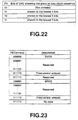
- a number to be used for dividing into data blocks is defined in terms of FN value. More specifically, "00” signifies no division and "01” signifies a division into two data blocks, while “10” signifies a division into 4 blocks and "11” signifies a division into 8 blocks.
- FMT is equal to "111111 2 " (no data)
- the fields of DBS, FN, QPC, SPH and DBC are ignored and no data block will be transferred.
- the highest order bit of FMT specifies SYT_available/SYT_not_available.
- FDF is defined for each FMT.
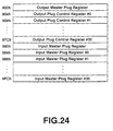
- each device does not possess both a plurality of oMPRs and a plurality of iMPRs at the same time, it can possess both a plurality of oPCRs and a plurality of iPCRs that correspond to respective plugs at the same time.
- the PCRs shown in FIG. 24 include a total of 31 oPCRs and a total of 31 iPCRs.
- the flow of isochronous data is controlled by operating the registers corresponding to the plugs involved in the data flow.
- FIGS. 25A through 25D are schematic illustrations of oMPR, oPCR, iMPR and iPCR, showing their respective configurations. More specifically, FIG. 25A shows the configuration of oMPR and FIG. 25B shows that of oPCR, while FIG. 25C shows the configuration of iMPR and FIG. 25D shows that of iPCR.
- the 2-bit data rate capacility area at the MSB side of oMPR and that of iMPR store respective codes indicating the maximum transmission rates at which the device can transmit and receive isochronous data respectively.
- the broadcast channel base of oMPR indicates the number of the channel that is used for broadcast outputs.
- the on-line area of at the MSB side of oPCR and that of iPCR indicate the operating condition of each of the plugs. More specifically, if the value there is 1, it indicates that the plug is ON-LINE. On the other hand, if the value there is 0, it indicates that the plug is OFF-LINE.
- the value of the broadcast connection counter of oPCR and that of iPCR indicate the presence (1) or absence (0) of a broadcast connection.
- the value of the 6-bit point-to-point connection counter of oPCR and that of iPCR indicate the number of point-to-point connections that the respective plugs have.
- the value of the 6-bit channel number of oPCR and that of iPCR indicate the number of isochronous channels that the respective plugs have.
- the value of the 2-bit data rate of oPCR indicates the real transmission rate of packets of output from the plug.
- the code stored in the 4-bit overhead ID of oPCR indicates the band width of the overhead of isochronous communication.
- the value of the 10-bit payload area of the oPCR indicates the maximum value of the data contained in an isochronous packet that the plug can handle.
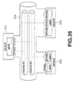
- FIG. 26 is a schematic illustration of point-to-point connection of devices that can be used for the purpose of the invention. Referring to FIG. 26, first device 101, second device 102 and third device 103 are connected to each other by way of a serial bus conforming to the IEEE1394 Standard.
- the iPCR[0] of the first device 101 and the oPCR[1] of the third device 103 are connected to each other by point-to-point connection by way of channel #1.
- Each of the broken lines in FIG. 26 indicates an isochronous data flow.
- the iPCR[1] of the first device 101 and the oPCR[0] of the second device 102 are connected to each other by point-to-point connection by way of channel #1.
- a broadcast connection is used to link an input plug or an output plug to an isochronous channel.
- the connection of an output plug and an isochronous channel is referred to as broadcast-out connection, whereas the connection of an input plug and an isochronous channel is referred to as broadcast-in connection.
- a broadcast connection can be established only by a device having a plug but can be released by some other device.
- a broadcast-out connection can be established at an output plug and a broadcast-in connection can be established at an input plug.
- a broadcast connection and a plurality of point-to-point connections can be connected to a single plug at the same time.
- a same isochronous channel is used to all the connections to a plug and used to transfer a same isochronous data flow.
- a plurality of independent applications can establish respective point-to-point connections between a same input plug and a same output plug.
- FIG. 27 is a schematic illustration of broadcast connection of devices that can be used for the purpose of the invention.
- first device 111, second device 112, third device 113, fourth device 114 and fifth device 115 are connected to bus 116 conforming to the IEEE1394 Standard.
- bus 116 conforming to the IEEE1394 Standard.
- Each of the broken lines in FIG. 27 indicates an isochronous data flow.
- the iPCR[1] of the first device 111 and the oPCR[0] of the fifth device 115 are connected to each other by two point-to-point connections.
- the iPCR[1] of the second device 113 and the oPCR[0] of the fifth device 115 are connected to each other by a point-to-point connection.
- the iPCR[0] of the fourth device 114 and the oPCR[0] of the fifth device 115 are connected to each other by way of three point-to-point connections.
- the oPCR[0] of the fifth device 115 is connected to the channel #1 by broadcast-out connection. Additionally, the iPCR[1] of the first device 111, the iPCR[0] of the second device 112, the iPCR[0] of the third device 113 and the iPCR[0] of the fourth device 114 are connected to the channel #1 by broadcast-in connection.
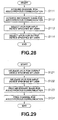
- Step S111 the node operating as isochronous resource manager for establishing input/output connections is requested to acquire a channel for isochronous communications. Then, the node operating as isochronous resource manager sets 0 to the bit corresponding to an idle channel in the channels available register of CSR in response to the request. Then, in Step S112, the node operating as isochronous resource manager is requested to acquire a band necessary for isochronous communications. Then, the node operating as isochronous resource manager decreases the value of the band widths available register of CSR by a numerical value corresponding to the requested band in response to the request.
- FIG. 29 is a flow chart of an operation of releasing an input/output connection that can be used for the purpose of the invention.
- Step S121 the channel number of the oPCR[k] and the point-to-point connection counter of the output device are cleared and thus the oPCR[k] is freed to become an idle oPCR.
- Step S122 the channel of the iPCR[j] and the point-to-point counter of the input device specified by the user are cleared and thus the iPCR[j] is freed to become an idle iPCR.
- An AV/C command set to be used for controlling AV devices will be described below as an example of FCP.
- FIG. 30 is a schematic illustration of a stack model of an AV/C command.
- a physical layer 111 there are shown a physical layer 111, a link layer 112, a transaction layer 113 and a serial bus management 114 that conform to the IEEE1394 Standard.
- FCP 115 conforms to the IEC61883 Standard and AV/C command set 116 conforms to the 1394TA specification.
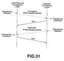
- FIG. 31 is a schematic illustration of the relationship between a command of the FCP 115 of FIG. 30 and a response to it.
- a controller and a target that is controlled by the controller.
- a command of the FCP and a response to it are exchanged between two nodes in a write transaction of asynchronous communication according to the IEEE1394 Standard.
- the target Upon receiving data, the target sends an acknowledgement to the controller to confirm the reception of the data.
- FIG. 33 is a schematic illustration of the data structure of a packet of an AV/C command.
- An AV/C command set is used to control AV devices, whose CTS (ID of the command set) is "0000".
- An AV/C command frame and an AV/C response frame are exchanged between two nodes by using the FCP.
- the response to a command is realized within 100ms.
- the upper half shows the header of the packet and the lower half shows the data block of the packet, while destination_ID shows the destination of the packet.
- commands for controlling the functional feature from outside
- command for inquiring the status of a specific functional feature from outside
- commands for inquiring the presence or absence of support for opcode and those (SPECIFIC INQUIRY) for inquiring the presence or absence of support for opcode and operands)
- NOTIFY for requesting a notification on the change in the status from outisde.
- the response to a command may vary depending on the type of command.
- the response to a CONTROL command may be NOT IMPLEMENTED, ACCEPTED, REJECTED or INTERIM.
- the response to a STATUS command may be NOT IMPLEMENTED, REJECTED, IN TRANSITION or STABLE.
- the response to a GENERAL INQUIRY or SPECIFIC INQUIRY command may be IMPLEMENTED or NOT IMPLEMENTED.
- the response to a NOTIFY command may be NOT IMPLEMENTED, REJECTED, INTERIM or CHANGED.
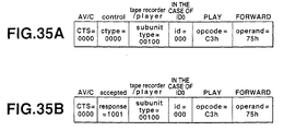
- the field of subunit type is provided to identify the function of the subunit in the device, which may be Tape Recorder/Player or Tuner. If a plurality of subunits of a same type exist, they are discriminated by means of respective subunit ID that are used for addressing.
- the field of opcode is provided to show indicate command and that of operand shows the parameter of the command.
- the field of Additional operands and that of padding are used additionally whenever necessary.
- the field of data CRC cyclic redundancy check
- FIGS. 34A through 34C are schematic illustrations of specific examples of AV/C commands.
- FIG. 34A shows an example of ctype/response.
- the upper half shows commands and the lower half shows response thereto.
- "0000", "0001", "0010”, “0011” and "0100” are allocated respectively to CONTROL, STATUS, SPECIFIC INQUIRY, NOTIFY and GENERAL INQUIRY, while "0101" and "0111” are reserved for a use in the future.
- FIG. 34B shows an example of subunit type.
- "00000”, “00011”, “00100”, “00101”, “00111”, “11100” and “11110” are allocated respectively to Video Monitor, Disc Recorder/Player, Tape Recorder/Player, Tuner, Video Camera, Vendor unique and subunit type extended to next byte. While “11111” is allocated to unit, it is used to something to be sent to the device such as ON/OFF of the power supply.
- FIG. 34C shows an example of opcode.
- An opcode table is provided for each subunit type and the example shown in FIG. 34C is one that is used when the subunit type is Tape Recorder/Player.
- An operand is defined for each opcode.
- "00h”, "50h”, “51h”, “52h”, “60h, “61h”, “62h”, “C1h”, C2h”, C3h” and “C4h” are allocated respectively to VENDOR-DEPENDENT, SEARCH MODE, TIME CODE, ATN, OPEN MIC, READ MIC, WRITE MIC, LOAD MEDIUM, RECORD, PLAY AND WIND.
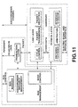
- the magneto-optical disc device 1 or the optical disc device 2 of the recording/reproduction device sends out a data stream to the serial bus 4 and the amplifier 3 receives the stream on the serial bus 4 and outputs it.
- the amplifier 3 reproduces the data transmitted to it in synchronism with the operation of the magneto-optical disc device 1 or the optical disc device 2.
- the magneto-optical disc device 1 receives an instruction for a reproducing operation in the form of an AV/C command in Step S11. More specifically, the CPU 11 of the magneto-optical disc device 1 shown in FIG. 2 receives an instruction in the form of an AV/C command by way of the interface 10 connected to the serial bus 4. Note that the AV/C command is transmitted from a controller (not shown) connected to the serial bus 4.
- Step S12 upon receiving the instruction and if possible, the magneto-optical disc device 1 transmits an isochronous packet containing the data reproduced from the magneto-optic disc to the serial bus 4.
- the CPU 11 is adapted to read data from a magneto-optical disc that may be an MD by means of an optical pickup 14.
- the data read by the CPU 11 are then turned into PCM audio data by the recording/reproduction system 13 and the encoder/decoder 16.
- the PCM audio data are then transmitted to the serial bus 40 by way of the interface 10 as an isochronous packet.
- the CPU 11 If it is impossible for the recording/reproduction device to start reproducing data because, for example, it is not provided with an magneto-optical disc device 1, the CPU 11 transmits an AV/C command to tell that the attempt for transmitting the data has failed. The command is also transmitted to the serial bus 4 by way of the interface 10.
- Step S21 the amplifier 3 constantly monitors the serial bus 4 for an isochronous packet. More specifically, the CPU 31 of the amplifier 3 monitors the serial bus 4 for an isochronous packet by way of the interface 35 connected to the serial bus 4.
- Step S22 If the CPU 31 finds an isochronous packet it can outputs in Step S22, it proceeds to Step S23. If, on the other hand, the CPU 31 does not find any isochronous packet it can outputs, it returns to Step S21. Due to Step S22, data of the type that the amplifier 3 cannot output will be excluded from the operation of the recording/reproduction device.
- the CPU 31 operating as means for determining if the amplifier 3 can output an isochronous packet or not reads the channels available register possessed by the isochronous resource manager of the serial bus 4 to find out the number of the channel through which an isochronous packet is output. Then, it confirms the CIP corresponding to the number of the channel through which an isochronous packet is output.
- the hatched area is used to determine if the CPU 31 can output an isochronous packet or not. More specifically, if the requirements of
- Step S23 the CPU 31 of the amplifier 3 determines if the isochronous packet that is determined to be capable of being output in Step S22 can be acquired or not. In order for the amplifier 3 to be able of acquire the isochronous packet, it is necessary that the amplifier 3 is not occupied by some other channel.
- the CPU proceeds to Step S24 if it is determined that the isochronous packet can be output, whereas the CPU 31 returns to Step S21 if it is determined that the isochronous packet cannot be output.
- Step S24 the CPU 31 of the amplifier 3 acquires and outputs the isochronous packet. More specifically, it is so controlled by the CPU 31 that the PCM audio data of the isochronous packet obtained by way of the interface 35 are output by way of the D/A conversion circuit 36.
- the acquisition of the isochronous packet by the amplifier 3 is carried out either by connecting the output plug of the output device indicated by SID of CIP header and its own plug on a point-to-point connection basis or by connecting the former to the channel being monitored on a broadcast-in connection basis.
- the magneto-optical disc device 1 receives an AV/C command in Step S31 and moves into a replay mode in Step S32. Then, in Step S33, it outputs the reproduced data to the serial bus 4 as isochronous packet.
- the amplifier 3 confirms the status of the magneto-optical disc device 1 as that of target in Step S41.
- the amplifier 3 acquires the right of reading the disc status descriptor by using READ OPEN that is one of the subfunctions of the OPEN DESCRIPTOR command for each connected device and an AV/C command.
- OPEN DESCRIPTOR command is in a format having opcode for storing OPEN DESCRIPTOR for acquiring the right of accessing the descriptor and operand containing descriptor_identifier for identifying the data to be accessed and the subfunction for indicating the operation to be executed by the target.
- the operation to be executed by the target is determined by the subfunction. More specifically, CLOSE (00 16 ) cancels the use of the descriptor and READ OPEN (00 16 ) opens the descriptor exclusively for reading and WRITE OPEN (00 16 ) opens the descriptor for both reading and writing.
- Step S42 the amplifier 3 reads Disc Status Descriptor from Source Plug Status Area Information Block-Plug Status Information Block-Operation Mode Information Block and confirms that it is in the replay mode to be used for the ongoing reproduction.
- OPEN DESCRIPTOR command is in a format having opcode for storing READ DESCRIPTOR for reading data from the descriptor and operand containing descriptor_identifier for identifying the data to be accessed, read_result_descriptor read out so as to be stored by the target, data_length indicating the length of the data read by the target and the starting point address to be read.
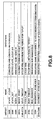
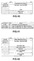
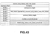
- Source Plug Status Area Information Block contains compound_length indicating the number of the remaining bytes of the block, "8802 16 " indicating source_plug_status_area_information_block as info_block_type, primary_fields_length, number_of_source_plug and plug_status_info_block.
- the number_of_source_plug field is used to identify the number of source plugs and indicates the number of plug status information blocks (plug_status_info_block) nested in the information block (info_block). On the other hand, each of the plug status information blocks (plug_status_info_block) indicates the status of the corresponding plug.
- Plug Status Information Block contains compound_length, "880516" indicating plug_status_info_block as info_block_type, primary_field_length, plug_number and secondary_fields, which is an info block defined so as to be nested in plug_status_info_block after the plug_number field.
- plug_status_info_block include one containing "8806 16 " for Info Block Type and "operating_mode_info_block" for Infor Block Name.
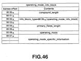
- Operating Mode Information Block for indicating the operating mode contains compound_length, "8806 16 " indicating operating_mode_info_block as info_block_type, primary_field_length and operating_mode_specific_information.
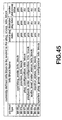
- the operating_mode field contains "C3 16 " indicating that the plug is replaying (play) the AV object. Therefore, it is possible to detect if the current mode is a replay mode or not by reading this operating_mode.
- the amplifier 3 closes the disc status descriptor by means of CLOSE command and releases the right of reading.
- Step S43 when the target device is in a replay mode
- Step S41 when the target device is not in a replay mode.
- Step S43 the amplifier 3 determines if it should acquire the isochronous packet or not.
- the amplifier 3 proceeds to Step S44 if it is determined that it should acquire the isochronous packet, whereas it returns to Step S41 if it is determined that it should not acquire the isochronous packet.
- Step S44 the amplifier 3 acquires the isochronous packet transmitted from the magneto-optical disc device 1 and outputs it.
- the amplifier 3 can input data either by connecting the output plug of the target device and its own input plug on a point-to-point connection basis or by connecting its own input plug to the output channel indicated by the output plug of the target device on a broadcast-in connection basis.
- this second mode of carrying out the invention it is possible to determine if the packet can be output or not on the basis of the value of the hatched area in the CIP header shown in A of FIG. 19 as in the case of the first mode of carrying out the invention.
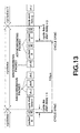
- the magneto-optical disc device 1 receives an instruction for data reproduction in the form of an AV/C command in Step S51 and notifies the amplifier 3 of the fact that it is transmitting an isochronous packet in Step S52.
- NOTIFY command that is one of available AV/C commands can be used for the notification.
- FIG. 49 is a schematic illustration of the relationship between NOTIFY command and a response to it.
- NOTIFY command (A in FIG. 49) is a command for requesting a notification on the change in the status to be made to the outside and therefore can be used to detect any change in the status of the target device (magneto-optical disc device 1).
- the target device Upon receiving the NOTIFY command, the target device returns INTERIM response (B in FIG. 49) to the controller device (amplifier 3). If there arises a change in the status of the target device, the target device returns CHANGED response (C in FIG. 49) to the controller device.
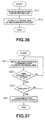
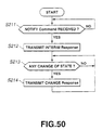
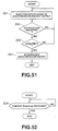
- FIG. 50 is a flow chart of a processing operation of the target device to be performed for the above process.
- the target device or the magneto-optical disc device 1 determines if it receives NOTIFY command from the controller device, or the amplifier 3. More specifically, NOTIFY command is Disc Status NOTIFY command.
- the magneto-optical disc device 1 Upon receiving the NOTIFY command, the magneto-optical disc device 1 transmits INTERIM command to the amplifier 3. If the magneto-optical disc device 1 does not receive NOTIFY command, it returns to Step S211.
- the magneto-optical disc device 1 After transmitting INTER command in Step S212, the magneto-optical disc device 1 determines if there is any change in the status or not in Step S213. If an AV/C command is transmitted as an instruction for a reproducing operation to the magneto-optical disc device 1 to change the status, the magneto-optical disc device 1 proceeds to Step S214, where it transmits CHANGE command to indicate the change in the status. If there is not any change in the status, the magneto-optical disc device 1 returns to Step S213.
- Step S53 shown in FIG. 48 the magneto-optical disc device 1 transmits the reproduced data to the serial bus 4 as isochronous packet.
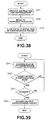
- the amplifier 3 waits for the output of the isochronous packet from the magneto-optical disc device 1 in Step S61.
- this notification is made by means of CHANGE command that is designed to be used to notify that the magneto-optical disc device is moved into a replay status.
- Step S61 Before starting the operation of Step S61, it is necessary for the amplifier 3 to transmits NOTIFY command to the magneto-optical disc device 1 to confirm that INTERIM RESPONSE is sent back as response. Therefore, this step corresponds to Step S211 and Step S212 in FIG. 50.
- Step S62 the amplifier 3 determines if it receives a notification from the magneto-optical disc device 1 telling that the latter has already started a replay operation or not.
- the amplifier 3 proceeds to Step S63 when it receives such a notification but returns to Step S61 when it does.
- the amplifier 3 determines if it receives CHANG RESPONSE indicating a change in the status from the magneto-optical disc device 1 or not in Step S62. It may be needless to say that the change in the status, if ever, should correspond to the replay operation to be conducted.
- Step S63 the amplifier 3 determines if it is in a status where it can receive an isochronous stream or not. If it is determined in Step S62 that the amplifier 3 can receive an isochronous stream, it proceeds to Step S64, where it acquires and outputs the isochronous stream. If, on the other hand, it is determined in Step S62 that the amplifier cannot receive an isochronous stream, it returns to the first step of Step S61.
Landscapes
- Engineering & Computer Science (AREA)
- Computer Networks & Wireless Communication (AREA)
- Signal Processing (AREA)
- Small-Scale Networks (AREA)
Abstract
Description
a first step of transmitting data to a data transmission bus as a periodical packet; and a second step of monitoring the periodical packet being transmitted in said first step and starting to receive the packet upon detecting the transmission of the packet as a packet available to it.
DBS = 0216 = 000000102 signifies that, if met, the size of the data block is 2 quadlets. The requirement of
FN = 016 signifies that, if met, the source packet is not divided into a plurality of data blocks as shown in FIG. 20. The requirement of
QPC = 016 signifies that, if met, the number of quadlets to be annexed to each source packet is equal to 0. The requirement of
SPH = 016 signifies that, if met, the packet does not have any source packet header. The requirement of
FMP = 1016 = 000100002 signifies that, if met, it indicates audio/music data that can be output by the
FDF = 0016 through 0216 = 000000002 through 000000102 indicates, if met, AM824 data with sampling frequencies of 32kHz (00), 44.1kHz (01) and 48kHz (02) in the field defined for a format that satisfies the requirement of
FMP = 1016 = 000100002.
Claims (40)
- A communication system of a plurality of devices connected to a predetermined bus, said system comprising:a first device adapted to transmit data as a periodical packet to the bus;a second device having a packet transmission monitoring means for monitoring a transmission of a periodical packet from said first device by way of the bus and a packet receiving means for receiving the periodical packet from said first device; andupon detecting the transmission of a packet available to said packet transmission monitoring means, said second device starts receiving said packet by said receiving means.
- The communication system according to claim 1, wherein said packet is an isochronous packet transmitted periodically by way of a channel having a predetermined band width.
- The communication system according to claim 1, wherein said packet has a field for describing the type of the format of the packet and said packet transmission monitoring means determines whether the packet is available or not on the basis of the value in said field.
- A communication system of a plurality of devices connected to a predetermined bus, said system comprising:a first device adapted to transmit data as a periodical packet to the bus;a second device having a status monitoring means for monitoring that status of said first device and a packet receiving means for receiving the periodical packet from said first device; andupon detecting the status of said first device read for transmitting a periodical packet, said second device starts receiving said packets by said receiving means.
- The communication system according to claim 4, wherein said packet is an isochronous packet transmitted periodically by way of a channel having a predetermined band width.
- The communication system according to claim 4, wherein said status is an operation mode of said first device and, upon detecting the operation mode to be for replaying by said status monitoring means, the second device starts receiving said packet by said receiving means.
- The communication system according to claim 6, wherein said status monitoring means acquires from said first device the reading right for reading the status of said first device and releases the reading right after reading said status.
- The communication system according to claim 4, wherein said second device further has a determining means for determining whether the packet is available or not on the basis of the header of said packet.
- A communication device to be connected to some other communication device by way of a predetermined bus, said communication device comprising:a packet transmission monitoring means for monitoring any transmission of a periodical packet from said other communication device by way of a bus;a packet receiving means for receiving a periodical packet from said other communication device; anda control means for causing said packet receiving means to receive the periodical packet from said other communication device upon detecting the packet as an available packet by said packet transmission monitoring means.
- The communication device according to claim 9, wherein said packet is an isochronous packet transmitted periodically by way of a channel having a predetermined band width.
- The communication device according to claim 9, wherein said packet has a field for describing the type of the format of the packet and said packet transmission monitoring means determines whether the packet is available or not on the basis of the value in said field.
- A communication device to be connected to some other communication device by way of a predetermined bus, said communication device comprising:a status monitoring means for monitoring the status of said other communication device;a packet receiving means for receiving a packet from said other communication device; anda control means for causing said packet receiving means to receive a packet by said packet receiving means upon detecting the status of said other communication device of being ready for transmitting a periodical packet.
- The communication device according to claim 12, wherein said packet is an isochronous packet transmitted periodically by way of a channel having a predetermined band width.
- The communication device according to claim 12, wherein said status is an operation mode of said first device and, upon detecting the operation mode to be for replaying by said status monitoring means, the second device starts receiving said packet by said receiving means.
- The communication device according to claim 12, wherein said status monitoring means acquires from said first device the reading right for reading the status of said first device and releases the reading right after reading said status.
- The communication device according to claim 12, wherein said second device further has a determining means for determining whether the packet is available or not on the basis of the header of said packet.
- A communication method for data communication to be conducted among devices connected to each other by way of a predetermined bus, said method comprising:a packet transmittimg step of transmitting data to the data transmission bus as a periodical packet;a monitoring step of monitoring the periodical packet being transmitted in said first step; anda packet receiving of starting to receive the packet upon detecting the transmission of the packet as a packet available to it.
- The communication method according to claim 17, wherein said packet is an isochronous packet transmitted periodically by way of a channel having a predetermined band width.
- A communication method for data communication to be conducted among devices connected to each other by way of a predetermined bus, said method comprising:a packet transmitting step of transmitting data to a data transmission bus as a periodical packet;a status detecting step of monitoring the status of said packet transmitting step and detecting the status ready for transmitting a periodical packet in said packet transmitting step; anda packet receiving step of starting to receive the packet upon detecting the status of said first step of being ready for transmitting a periodical packet.
- The communication method according to claim 19, wherein said packet is an isochronous packet transmitted periodically by way of a channel having a predetermined band width.
- A communication system of a plurality of communication devices connected to a predetermined bus, said communication system comprising:a first communication device adapted to transmit data as a periodical packet to said bus;a second communication device having a packet receiving means for receiving the periodical packet transmitted from said first device;said first transmission device having:a receiving means for receiving the notification request transmitted from said second device and requesting a notification of the status of said first communication device of being ready to start transmitting packets;a notification command transmitting means for transmitting a notification command for notifying the status of being ready to start transmitting packets upon receiving said notification request command and coming into a status of being ready to start transmitting a packet; anda data transmitting means for transmitting data to said second communication device as a packet;said second transmission device having:a notification request command transmitting means for generating a notification request command for requesting a notification of the status of said first communication device of being ready to start transmitting a packet and transmitting it to said first communication device;a notification command receiving means for receiving a notification command transmitted from said first communication means to notify the status of said first communication device of being ready to start transmitting a packet in response to said notification request command; anda packet receiving means adapted to start receiving a packet from said first device according to the received notification command.
- The communication system according to claim 21, wherein said packet is an isochronous packet transmitted periodically by way of a channel having a predetermined band width.
- The communication system according to claim 21, wherein said notification command contains status information on said first communication device and said second communication device confirms the status of said first communication device on the basis of the notification command.
- The communication system according to claim 21, wherein said status information indicates the operation mode of said first communication device and said second communication device starts receiving said packet upon detecting the operation mode to be for replaying.
- A communication device to be connected to some other communication device adapted to transmit a packet by way of a predetermined bus, said communication device comprising:a notification request command transmitting means for generating a notification request command for requesting a notification from said other communication device of the status thereof of being ready to start transmitting a packet and transmitting it to said other communication device;a notification command receiving means for receiving the notification command transmitted from said other communication device for notifying the status of said other communication device of being ready to start transmitting a packet in response to said notification request command; anda packet receiving means adapted to start receiving a packet from said other communication device according to said received notification command.
- The communication device according to claim 25, wherein said packet is an isochronous packet transmitted periodically by way of a channel having a predetermined band width.
- The communication device according to claim 26, wherein said notification command contains status information on said first communication device and said second communication device confirms the status of said first communication device on the basis of the notification command.
- The communication system according to claim 27, wherein said status information indicates the operation mode of said first communication device and said second communication device starts receiving said packet upon detecting the operation mode to be for replaying.
- A communication device for transmitting data to some other communication device, said communication device comprising:a receiving means for receiving the notification request command transmitted from said other communication device for requesting a notification of the status of said communication device of being ready to start transmitting a packet;a notification command transmitting means for transmitting a notification command for notifying the status thereof of being ready to start transmitting a packet upon receiving said notification request command and becoming ready to start transmitting a packet; anda data transmitting means for transmitting data to said other communication device as a packet.
- The communication device according to claim 29, wherein said packet is an isochronous packet transmitted periodically by way of a channel having a predetermined band width.
- The communication device according to claim 29, wherein said notification command contains status information on said communication device.
- The communication system according to claim 31, wherein said status information indicates the operation mode of said communication device.
- A communication method for communicating with some other communication device adapted to transmit a packet by way of a predetermined bus, said communication method comprising:a notification command transmitting step of generating a notification request command for requesting a notification of the status of said other communication device of being ready to start transmitting a packet and transmitting said request to said other communication device;a notification command receiving step of receiving the notification command transmitted from said other communication device for notifying the status thereof of being ready to start transmitting a packet in response to said notification request command; anda packet receiving step of starting to receive a packet from said other communication device according to said received notification command.
- The communication method according to claim 33, wherein said packet is an isochronous packet transmitted periodically by way of a channel having a predetermined band width.
- The communication method according to claim 34, wherein said notification command contains status information on said first communication device and said second communication device confirms the status of said first communication device on the basis of the notification command.
- The communication method according to claim 34, wherein said status information indicates the operation mode of said first communication device and said second communication device starts receiving said packet upon detecting the operation mode to be for replaying.
- A communication method for transmitting data from a communication device to some other communication device as packet, said communication method comprising:a receiving step of receiving the notification request command transmitted from said other communication device for requesting a notification of the status of said communication device of being ready to start transmitting a packet;a notification command transmitting step of receiving said notification request command and transmitting a notification command for notifying the status of said communication device of being ready to start transmitting a packet upon becoming ready to start transmitting a packet; anda data transmitting step of transmitting data to said other communication device as a packet.
- The communication method according to claim 37, wherein said packet is an isochronous packet transmitted periodically by way of a channel having a predetermined band width.
- The communication device according to claim 37, wherein said notification command contains status information on said communication device.
- The communication system according to claim 37, wherein said status information indicates the operation mode of said communication device.
Applications Claiming Priority (4)
| Application Number | Priority Date | Filing Date | Title |
|---|---|---|---|
| JP2000052196A JP2001237910A (en) | 2000-02-23 | 2000-02-23 | Communication device and method |
| JP2000052196 | 2000-02-23 | ||
| JP2000052195 | 2000-02-23 | ||
| JP2000052195A JP2001237865A (en) | 2000-02-23 | 2000-02-23 | Communication device and method |
Publications (2)
| Publication Number | Publication Date |
|---|---|
| EP1128616A2 true EP1128616A2 (en) | 2001-08-29 |
| EP1128616A3 EP1128616A3 (en) | 2001-09-12 |
Family
ID=26586276
Family Applications (1)
| Application Number | Title | Priority Date | Filing Date |
|---|---|---|---|
| EP01301549A Withdrawn EP1128616A3 (en) | 2000-02-23 | 2001-02-21 | Communication system, communication device and communication method |
Country Status (3)
| Country | Link |
|---|---|
| US (1) | US20010024445A1 (en) |
| EP (1) | EP1128616A3 (en) |
| KR (1) | KR20010085515A (en) |
Families Citing this family (10)
| Publication number | Priority date | Publication date | Assignee | Title |
|---|---|---|---|---|
| JP3325839B2 (en) * | 1998-10-15 | 2002-09-17 | パイオニア株式会社 | Information transmitting apparatus and method, information receiving apparatus and method, and information transmitting and receiving apparatus and method |
| EP1199840A1 (en) * | 2000-10-19 | 2002-04-24 | THOMSON multimedia | Method for connecting an IEEE1394 remote device to a cluster of IEEE1394 devices through a wireless link |
| JP2004158981A (en) * | 2002-11-05 | 2004-06-03 | Toshiba Corp | Communication device and communication method |
| KR100957797B1 (en) * | 2002-11-13 | 2010-05-13 | 엘지전자 주식회사 | Content information playback method in interactive optical disk device and content information provision method in content providing server |
| DE10337699B4 (en) * | 2003-08-16 | 2006-01-12 | Phoenix Contact Gmbh & Co. Kg | Method and device for transmitting data over a bus network using the broadcast principle |
| KR20080053334A (en) * | 2005-10-03 | 2008-06-12 | 마쯔시다덴기산교 가부시키가이샤 | Communication device |
| KR101135101B1 (en) * | 2005-10-17 | 2012-04-16 | 엘지전자 주식회사 | Method for data filed padding data length code using in controller area network |
| JP4834148B2 (en) * | 2007-03-30 | 2011-12-14 | 富士通セミコンダクター株式会社 | Data transfer method and data transfer apparatus |
| JP6464035B2 (en) * | 2015-06-02 | 2019-02-06 | 株式会社日立製作所 | Control system |
| US10148453B2 (en) * | 2016-02-24 | 2018-12-04 | Qualcomm Incorporated | Using update slot to synchronize to Bluetooth LE isochronous channel and communicate state changes |
Family Cites Families (4)
| Publication number | Priority date | Publication date | Assignee | Title |
|---|---|---|---|---|
| JP3783282B2 (en) * | 1996-06-04 | 2006-06-07 | ソニー株式会社 | COMMUNICATION CONTROL METHOD, COMMUNICATION SYSTEM AND ELECTRONIC DEVICE USED FOR THE SAME |
| US5991842A (en) * | 1996-08-27 | 1999-11-23 | Canon Kabushiki Kaisha | Communication system for providing digital data transfer, electronic equipment for transferring data using the communication system, and an interface control device |
| JP3862371B2 (en) * | 1996-08-27 | 2006-12-27 | キヤノン株式会社 | Electronic device and control method |
| JPH10224424A (en) * | 1997-02-12 | 1998-08-21 | Matsushita Electric Ind Co Ltd | Data transmitting device, data receiving device, and medium |
-
2001
- 2001-02-21 EP EP01301549A patent/EP1128616A3/en not_active Withdrawn
- 2001-02-21 US US09/789,974 patent/US20010024445A1/en not_active Abandoned
- 2001-02-23 KR KR1020010009187A patent/KR20010085515A/en not_active Withdrawn
Also Published As
| Publication number | Publication date |
|---|---|
| KR20010085515A (en) | 2001-09-07 |
| EP1128616A3 (en) | 2001-09-12 |
| US20010024445A1 (en) | 2001-09-27 |
Similar Documents
| Publication | Publication Date | Title |
|---|---|---|
| JP2002016655A (en) | Transmission method, transmission system, transmission device, and transmission control device | |
| US6823408B2 (en) | Electronic equipment, and method for controlling state of physical layer circuit therefor | |
| EP1128616A2 (en) | Communication system, communication device and communication method | |
| US6910085B2 (en) | Audio visual system having a serial bus for identifying devices connected to the external terminals of an amplifier in the system | |
| US20020004711A1 (en) | Control device and control method | |
| JP2002051055A (en) | Communication control method, communication system and communication device | |
| JP4320993B2 (en) | Device control method, transmission apparatus and medium | |
| JP2001156807A (en) | Transmission method, transmission system and transmission device | |
| JPWO2001026295A1 (en) | Equipment control method, transmission device and medium | |
| JP2002057683A (en) | Control device and control method | |
| EP1182827B1 (en) | Information control method, information processing apparatus, and information control system | |
| KR20020097288A (en) | Data transmission method and data transmission device | |
| US20020041602A1 (en) | Communication control method, communication system, and communication apparatus | |
| JP2001237910A (en) | Communication device and method | |
| JP2003229857A (en) | Serial bus system, device for managing band of serial bus, and communication equipment | |
| JP2001237865A (en) | Communication device and method | |
| KR20010071972A (en) | Communication method, communication device, and communication system | |
| US20020073169A1 (en) | Information processing apparatus, information processing system and method thereof | |
| JP2002051054A (en) | Communication control method, communication system and communication device | |
| JP2002051056A (en) | Communication control method, communication system and communication device | |
| JPWO2000072519A1 (en) | Communication method, communication device, and communication system | |
| KR20010071968A (en) | Communication method, communication system, and electronic device | |
| JPWO2000070841A1 (en) | Communication method, communication device, communication system, and provision medium | |
| JP2001358800A (en) | Information processing system, information processing apparatus, and their methods | |
| JPWO2000072551A1 (en) | Communication method, communication system, and electronic device |
Legal Events
| Date | Code | Title | Description |
|---|---|---|---|
| PUAI | Public reference made under article 153(3) epc to a published international application that has entered the european phase |
Free format text: ORIGINAL CODE: 0009012 |
|
| PUAL | Search report despatched |
Free format text: ORIGINAL CODE: 0009013 |
|
| AK | Designated contracting states |
Kind code of ref document: A2 Designated state(s): AT BE CH CY DE DK ES FI FR GB GR IE IT LI LU MC NL PT SE TR Kind code of ref document: A2 Designated state(s): DE FR GB |
|
| AX | Request for extension of the european patent |
Free format text: AL;LT;LV;MK;RO;SI |
|
| AK | Designated contracting states |
Kind code of ref document: A3 Designated state(s): AT BE CH CY DE DK ES FI FR GB GR IE IT LI LU MC NL PT SE TR |
|
| AX | Request for extension of the european patent |
Free format text: AL;LT;LV;MK;RO;SI |
|
| RIC1 | Information provided on ipc code assigned before grant |
Free format text: 7H 04L 12/64 A, 7H 04L 12/28 B |
|
| 17P | Request for examination filed |
Effective date: 20020226 |
|
| AKX | Designation fees paid |
Free format text: DE FR GB |
|
| STAA | Information on the status of an ep patent application or granted ep patent |
Free format text: STATUS: THE APPLICATION HAS BEEN WITHDRAWN |
|
| 18W | Application withdrawn |
Effective date: 20030725 |