The present invention regards a structure for electrically
connecting microelectromechanical devices, in particular
microactuators for hard disk drivers.
As is known, with the advent of new microactuating devices for
hard disk drivers, the problem has arisen to devise an effective
method for carrying the signal from the head (which is moving)
to a fixed point located, for example, on the suspension.
For this purpose, electrical connections of a conductive
material, generally metal, are used so as to ensure a low
mechanical as well as electrical resistance.
In particular, the connection must not modify the mechanical
resistance of the system including the head and the
microactuating device and, specifically, the torsional
resistance of the movable part of the microactuating device with
respect to the fixed part. In fact, the movable part of the
microactuating device (rotor) is connected to the fixed part via
suspension regions called "springs" and, in general terms, the
overall mechanical resistance of the system is affected both by
the resistance of the springs and by the resistance of the
electrical connections. Since the processes for forming the
springs and the electrical connections are generally very
different, in the worst case the overall mechanical resistance
of the system may be equal to the sum of the two resistances.
Ideally, the mechanical resistance of the connections should be
negligible as compared to that of the springs, which are sized
so as to bestow on the entire microelectromechanical system the
desired torsional rigidity. With current solutions, this,
however, is not possible.
The aim of the present invention is therefore to devise a
structure for electrically connecting movable and fixed parts of
a microelectromechanical device that will overcome the above
problem.
According to the present invention, a microelectromechanical
device is provided, as defined in Claim 1.
For a better understanding of the present invention, preferred
embodiments thereof will now be described, simply as nonlimiting
examples, with reference to the attached drawings,
wherein:
- Figure 1 is a top view of a microelectromechanical device
provided with a known connection structure;
- Figure 2 is a cross-section taken along line II-II of Figure
1;
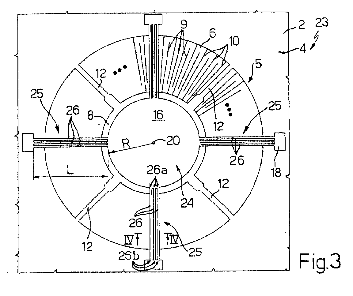
- Figure 3 shows a top view of the microelectromechanical device
of Figure 1 provided with a connection structure according to
the invention;
- Figure 4 is a cross-section taken along line IV-IV of Figure
3;
- Figure 5 shows a top view of a microactuator for a hard disk
driver, provided with a connection structure according to the
invention;
- Figure 6 shows a cross-section taken along line VI-VI of
Figure 5;
- Figure 7 shows a cross-section taken along line VII-VII of
Figure 6; and
- Figure 8 shows a top view of a microactuator of a linear type,
provided with a connection structure according to the invention.
Figure 1 is a simplified representation of a known generic
microelectromechanical device, formed in a semiconductor
material body 2. The microelectromechanical device 1 may form a
microactuator, a microsensor for detecting motion or pressure,
or some other structure provided with suspended parts, which are
movable with respect to the fixed part. The
microelectromechanical device thus comprises an inner, movable,
part (forming a rotor 3) and an outer, fixed, part 4 (forming
the stator 5), the two parts being separated by trenches 6.
In detail, the rotor 3 comprises a central region 8 having a
circular shape and a plurality of movable electrodes 9 which
extend radially from the central region 8 towards the fixed part
4, and are illustrated only partially, given the symmetry of the
structure. The stator 5 comprises a plurality of fixed
electrodes 10 extending radially inwards; in particular, each
fixed electrode 10 extends between two adjacent movable
electrodes 9.
The rotor 3 is suspended and is connected to the body through
anchorage and suspension elements, also referred to as "springs"
12, which extend radially from the central region 8 as far as
the fixed part 4. Insulating regions (not shown) guarantee, in a
known way, electrical insulation of the springs 12, and thus of
the rotor 3, with respect to the fixed part. Likewise, further
insulating regions (not shown) ensure electrical insulation of
the fixed electrodes 10 from the rest of the fixed part 4 and
from one another, so as to enable separate biasing of the two
fixed electrodes set on either side of each movable electrode 9,
in a per se known manner and thus not described in detail.
An electrical connection structure 15 for the rotor 3 extends
above the rotor 3 itself and comprises a central plate 16, which
is coaxial with and has a slightly smaller diameter than the
central region 8, and a plurality of connection arms 17 (four,
in the example illustrated) which extend from the central plate
16 as far as the fixed part 4. The connection arms 17 are
preferably floating and have at the ends anchorage portions 18
connected to special biasing regions (not shown) formed in the
fixed part 4 or to bonding wires (not shown either) .
Alternatively, the connection arms 17 may extend above the
springs 12. The connection arms 17 are of conducting material,
such as metal, obtained through photolithographic techniques
that are extensively used in microelectronics.
Each connection arm 17 is connected internally to the central
plate 16 in a movable anchorage point 17a at an inner end of the
connection arm 17 and is set at a distance R form the rotation
axis 20 of the rotor 3. In addition, each connection arm 17 is
connected externally to the fixed part 4 in a fixed anchorage
point 17b corresponding with an outer end of the connection arm
17. Between the movable anchorage point 17a and the fixed
anchorage point 17b, each connection arm 17 has a length L. The
cross-section of each connection arm 17 is shown in Figure 2 and
typically has a rectangular shape, of width W, thickness T, and
area A = W × T.
In general, the torsional rigidity
Kϑ of a set of connection arms
anchored externally to the movable part is given by the
following equation:
where
E is Young's modulus;
W is the width;
T is the thickness;
L is the length;
N is the number of connection arms; and
R is
the distance between the
movable anchorage point 17a and the
center of rotation of the connection structure.
In the example shown in Figure 1, then, the torsional rigidity
K91 of the
connection structure 16 is
In order to reduce the torsional rigidity
Kϑ1 of the
connection
arms 17, according to the invention each
connection arm 17 is
divided into a number of connection sub-arms, so as to have a
same current passage area A (and thus a same total electrical
resistance). In particular, each
connection arm 17 is replaced
by
m sub-arms, each having a width
W1 =
W/m. All the other
parameters remain unchanged.
In this condition, the connection structure has
N1 =
N × m sub-arms,
each having a width
W1 =
W/m, as indicated above. A
connection structure of this sort has the following torsional
rigidity
Kϑm :
An embodiment of a connection structure 24 according to the
invention is shown in Figure 3, wherein same parts as in Figure
1 are designated by the same reference numbers.
In detail, in Figure 3 a microelectromechanical device 23
comprises a connection structure 24, preferably of a metal,
including four connection elements 25, each including three sub-arms
26 connected together in parallel. Each sub-arm 26 is
connected internally to the central plate 16 in a movable
anchorage point 26a at the inner end of the sub-arm 26 and is
set at a distance R from the rotation axis 20 of the rotor 3. In
addition, each sub-arm 26 is connected externally to the fixed
part 4 in a fixed anchorage point 26b at the outer end of the
sub-arm 26. The sub-arms 26 of each connection element 25 are
connected together at the movable anchorage point 26a and at the
fixed anchorage point 26b.
Between the movable anchorage point 26a and the fixed anchorage
point 26b, each sub-arm 26 has a length L equal to that of the
connection arms 17 of Figure 1. The cross section of each sub-arm
26 is shown in Figure 4 and has a width W2 = W/3, a
thickness T, and an area A1 = W x T/3.
Consequently, the
connection structure 24 has a torsional
rigidity
Kϑ2 as follows:
and thus equal to 1/9 of the torsional rigidity
K ϑ of the
connection structure 17 of Figure 1.
As indicated, each connection element 25 has an area A = W × T
equal to that of each connection arm 17 of Figure 1. Since the
electrical resistance R e of each connection element 25 is given
by:
Re = ρL/A
where ρ is the resistivity of the material, and L and A are,
respectively, the length and the area of each connection
element, as indicated above, each connection element has
electrical resistance equal to that of a connection arm 17 of
Figure 1.
Another example of microelectromechanical device to which the
invention can be applied is shown in Figures 5-7 and regards a
microactuator 30 for micrometric adjusting the position of a
read/write head (or "slider") with respect to a hard disk.
In detail, the microactuator 30 is formed in a semiconductor
material body 31 having a face fixed to a slider 32 (shown in
see-through view in Figure 5), and on an opposite face fixed to
a suspension 33 belonging to a hard disk driver 34 (Figure 6).
The semiconductor material body 31 (Figure 6) moreover forms a
supporting structure 37 surrounding the microactuator 30 above
and laterally, and comprising a central supporting region 38,
which is fixed, an annular supporting region 39, which is
movable, and an outer region 40, which is fixed, the regions 38,
39 and 40 being separated from one another by trenches 36a, 36b.
The microactuator 30 (Figures 6 and 7) comprises a rotor 41 and
a stator 42. The rotor 41 includes a movable annular region 43,
directly anchored to the annular supporting region 39 and
anchored to the central supporting region 38 through suspension
arms 44, elastic suspension elements, referred to as "springs",
45, and a central anchorage region 46. The springs 45 are
suspended and are separated from the supporting structure 37 by
an air gap, as is evident in Figure 6. Movable electrodes 47
extend from the movable annular region 43 and are directed
radially inwards.
The central anchorage region 46 is fixed and is anchored,
through connection and welding regions 48, to the suspension 33,
welded also to the outer region 40. In practice, then, the
central anchorage region 46 is an integral part of the
supporting structure 37.
The stator 41 comprises four anchorage and supporting sectors 50
and fixed electrodes 52. The anchorage and supporting sectors 50
are anchored to the central supporting region 38 (in a way not
shown) through insulating regions (not shown, either) and extend
between pairs of adjacent springs 45, while the fixed electrodes
52 extend radially outwards from the anchorage and supporting
sectors 50 (Figure 7).
As is evident from Figures 5 and 6, the slider 32 is fixed to
the annular supporting region 39 of the supporting structure 37
through a connection structure 55 comprising four fixing regions
56 and four connection elements 57. In particular, the fixing
regions 56 extend between the slider 32 and the annular
supporting region 39 and are electrically insulated from the
latter through insulating regions 58 which extend only
underneath the fixing regions 56 and appear only in Figure 6,
even though they are set at a distance from the sectional plane
of Figure 6.
Each one of the connection elements 57 comprises three sub-arms
60. Each sub-arm 60 is floating and extends from a movable
anchorage point 60a, where the sub-arm 60 is connected to the
other sub-arms 60 of the same connection element 57, and to the
respective fixing region 56, as far as a fixed anchorage point
60b on the outer region 40, which is common to all the sub-arms
60 of the same connection element 57 (Figure 5).
In practice, also here the sub-arms 60 are connected in
parallel.
Similarly to the embodiment of Figure 3, therefore, the sub-arms
60 have a reduced torsional resistance and have electrical
resistance which is equal to that of a connection structure of a
known type, i.e., one comprising a single connection arm for
each fixing region 56, having the same total area.
The present invention can moreover be applied to micromechanical
structures of a linear type, such as linear microactuators and
accelerometers, oscillators, and mechanical filters and
gyroscopes. As an example, Figure 8 presents a schematic
illustration of a linear sensor 70 according to the present
invention.
In detail, the linear sensor 70 of Figure 8 is formed in a
semiconductor material body 71 and comprises a movable mass
("shuttle") 72 and a fixed part 73 (forming a stator 74), which
are separated by trenches 75.
The movable mass 72 comprises a central region 75, which is
suspended and also has a rectangular shape, connected to the
fixed part 73 via four suspension arms or springs 76. Movable
electrodes 80 extend from the two longer sides of the central
region 75 and perpendicular thereto, and face fixed electrodes
81 which extend parallel to the movable electrodes 80 from the
fixed part 73 towards the central region 75. The fixed
electrodes 81 form the stator 74.
Insulating regions (not shown) ensure, in a known way,
electrical insulation of the movable mass 72 from the fixed
part. Likewise, further insulating regions (not shown) ensure
electrical insulation of the fixed electrodes 81 from the rest
of the fixed part 73 and from one another, so as to enable
separate biasing of the two fixed electrodes set on either side
of each movable electrode 80, in a per se known manner and thus
not described in detail.
An electrical connection structure 85 extends above the movable
mass 72 and comprises four metal regions 86 and four connection
elements 87, each of which includes three sub-arms connected in
parallel. Each sub-arm 88 is connected to the respective metal
region 86 in a movable anchorage point 88a at a movable end of
the sub-arm 88. In addition, each sub-arm 88 is connected
externally to the fixed part 73 in a fixed anchorage point 88b
at an outer end of the sub-arm 88. The sub-arms 88 of each
connection element 87 are connected together at the movable
anchorage point 88a and at the fixed anchorage point 88b.
As for the actuators shown in Figures 3, 4 and 5-7, the
connection elements 87 are divided into a plurality of sub-arms
88 (three, in the example illustrated), the width of which W3 is
a submultiple of the width W necessary for each connection
element to have a given electrical resistance, which in turn is
determined by the amount of current that is to pass in the
connection element and by the operating conditions of the
microactuator. In the illustrated example, W3 = W/3. In this
way, the electrical resistance of each connection element
remains unvaried, whilst its torsional resistance decreases.
In particular, the rigidity K of an electrical connection
structure for a microelectromechanical device of a linear type
having N electrical connection elements of width W, thickness T
and length L is given by the following equation:
K=EN W 3 T L
where E is Young's modulus.
In the case of the electrical connection elements 87 having a
width W3 = W/3, Eq. (2) becomes
K 3=3EN W 3 T 33 L = K/9
and, in general, with m sub-arms of width W/m, the rigidity Km is
Km = K/m
The advantages of the described connection structure are evident
from the above description. In particular, it is emphasized that
the connection structure according to the invention ensures a
negligible mechanical of the electrical connection elements with
respect to the mechanical suspension elements (springs)
resistance, for a same current carrying capacity. The connection
structure can be formed using normal techniques employed in
microelectronics, and in particular in the fabrication of
microelectromechanical devices, with just a modification of the
mask for defining the electrical connection elements, and thus
without any increase in costs and without any modification of
other parts of the microelectromechanical device.
Finally, it is clear that numerous variations and modifications
may be made to the microelectromechanical device described and
illustrated herein, all falling within the scope of the
invention, as defined in the attached claims. In particular,
although in the illustrated examples each connection element
includes three sub-arms, the number of sub-arms present may vary
according to the desired reduction in torsional resistance, the
available spaces, and the minimum dimensions allowed by the
definition techniques that are used for forming the sub-arms.
In addition, the described connection structure is equally
applicable to microelectromechanical devices of a rotary type,
in which the anchorage area for the movable part is external,
and the anchorage area for the fixed part is internal. In this
case, Eq. (1) must be modified in such a way that the sign "+"
inside the square brackets becomes "-" (subtraction).